EP1362989A2 - control system and method for variable valve actuation system - Google Patents
control system and method for variable valve actuation system Download PDFInfo
- Publication number
- EP1362989A2 EP1362989A2 EP03006345A EP03006345A EP1362989A2 EP 1362989 A2 EP1362989 A2 EP 1362989A2 EP 03006345 A EP03006345 A EP 03006345A EP 03006345 A EP03006345 A EP 03006345A EP 1362989 A2 EP1362989 A2 EP 1362989A2
- Authority
- EP
- European Patent Office
- Prior art keywords
- valve
- engine
- intake
- intake valve
- valve actuation
- Prior art date
- Legal status (The legal status is an assumption and is not a legal conclusion. Google has not performed a legal analysis and makes no representation as to the accuracy of the status listed.)
- Withdrawn
Links
Images


Classifications
-
- F—MECHANICAL ENGINEERING; LIGHTING; HEATING; WEAPONS; BLASTING
- F02—COMBUSTION ENGINES; HOT-GAS OR COMBUSTION-PRODUCT ENGINE PLANTS
- F02D—CONTROLLING COMBUSTION ENGINES
- F02D13/00—Controlling the engine output power by varying inlet or exhaust valve operating characteristics, e.g. timing
- F02D13/02—Controlling the engine output power by varying inlet or exhaust valve operating characteristics, e.g. timing during engine operation
- F02D13/0269—Controlling the valves to perform a Miller-Atkinson cycle
-
- F—MECHANICAL ENGINEERING; LIGHTING; HEATING; WEAPONS; BLASTING
- F01—MACHINES OR ENGINES IN GENERAL; ENGINE PLANTS IN GENERAL; STEAM ENGINES
- F01L—CYCLICALLY OPERATING VALVES FOR MACHINES OR ENGINES
- F01L13/00—Modifications of valve-gear to facilitate reversing, braking, starting, changing compression ratio, or other specific operations
- F01L13/06—Modifications of valve-gear to facilitate reversing, braking, starting, changing compression ratio, or other specific operations for braking
-
- F—MECHANICAL ENGINEERING; LIGHTING; HEATING; WEAPONS; BLASTING
- F01—MACHINES OR ENGINES IN GENERAL; ENGINE PLANTS IN GENERAL; STEAM ENGINES
- F01L—CYCLICALLY OPERATING VALVES FOR MACHINES OR ENGINES
- F01L9/00—Valve-gear or valve arrangements actuated non-mechanically
- F01L9/10—Valve-gear or valve arrangements actuated non-mechanically by fluid means, e.g. hydraulic
- F01L9/11—Valve-gear or valve arrangements actuated non-mechanically by fluid means, e.g. hydraulic in which the action of a cam is being transmitted to a valve by a liquid column
- F01L9/12—Valve-gear or valve arrangements actuated non-mechanically by fluid means, e.g. hydraulic in which the action of a cam is being transmitted to a valve by a liquid column with a liquid chamber between a piston actuated by a cam and a piston acting on a valve stem
-
- F—MECHANICAL ENGINEERING; LIGHTING; HEATING; WEAPONS; BLASTING
- F01—MACHINES OR ENGINES IN GENERAL; ENGINE PLANTS IN GENERAL; STEAM ENGINES
- F01L—CYCLICALLY OPERATING VALVES FOR MACHINES OR ENGINES
- F01L1/00—Valve-gear or valve arrangements, e.g. lift-valve gear
- F01L1/34—Valve-gear or valve arrangements, e.g. lift-valve gear characterised by the provision of means for changing the timing of the valves without changing the duration of opening and without affecting the magnitude of the valve lift
- F01L1/344—Valve-gear or valve arrangements, e.g. lift-valve gear characterised by the provision of means for changing the timing of the valves without changing the duration of opening and without affecting the magnitude of the valve lift changing the angular relationship between crankshaft and camshaft, e.g. using helicoidal gear
- F01L1/3442—Valve-gear or valve arrangements, e.g. lift-valve gear characterised by the provision of means for changing the timing of the valves without changing the duration of opening and without affecting the magnitude of the valve lift changing the angular relationship between crankshaft and camshaft, e.g. using helicoidal gear using hydraulic chambers with variable volume to transmit the rotating force
- F01L2001/34423—Details relating to the hydraulic feeding circuit
- F01L2001/34446—Fluid accumulators for the feeding circuit
-
- F—MECHANICAL ENGINEERING; LIGHTING; HEATING; WEAPONS; BLASTING
- F02—COMBUSTION ENGINES; HOT-GAS OR COMBUSTION-PRODUCT ENGINE PLANTS
- F02B—INTERNAL-COMBUSTION PISTON ENGINES; COMBUSTION ENGINES IN GENERAL
- F02B2275/00—Other engines, components or details, not provided for in other groups of this subclass
- F02B2275/32—Miller cycle
-
- Y—GENERAL TAGGING OF NEW TECHNOLOGICAL DEVELOPMENTS; GENERAL TAGGING OF CROSS-SECTIONAL TECHNOLOGIES SPANNING OVER SEVERAL SECTIONS OF THE IPC; TECHNICAL SUBJECTS COVERED BY FORMER USPC CROSS-REFERENCE ART COLLECTIONS [XRACs] AND DIGESTS
- Y02—TECHNOLOGIES OR APPLICATIONS FOR MITIGATION OR ADAPTATION AGAINST CLIMATE CHANGE
- Y02T—CLIMATE CHANGE MITIGATION TECHNOLOGIES RELATED TO TRANSPORTATION
- Y02T10/00—Road transport of goods or passengers
- Y02T10/10—Internal combustion engine [ICE] based vehicles
- Y02T10/12—Improving ICE efficiencies
Definitions
- the present invention is directed to a system and method for controlling a variable valve actuation system. More particularly, the present invention is directed to a system and method for controlling a variable valve actuation system in an internal combustion engine.
- Fuel efficiency and emission reductions are a concern in the design and operation of an internal combustion engine, such as, for example, a diesel, gasoline, or natural gas engine. Accordingly, a significant amount of research and development work is being directed towards reducing the emissions while maintaining or improving the fuel efficiency of these types of engines. Any increase in fuel efficiency will directly translate to a reduction in the fuel costs associated with operating the engine along with the production of carbon dioxide.
- Oxides of nitrogen are another constituent of engine emissions that researchers are trying to reduce. NOx production is generally proportional to temperatures of combustion and volume of excess air. Unfortunately, fuel efficiency also is generally proportional to these same factors. Conventional NOx reduction techniques include increasing the mass of inert matter, such as water or recirculated exhaust gas, in a combustion chamber prior to combusting a fuel air mixture. These measures may reduce the temperature of combustion and may also reduce the fuel efficiency.
- One possible approach to improving fuel efficiency involves improving control over the flow of gases into and out of the engine. This may be accomplished by modifying the typical engine valve actuation system to provide flexibility in the actuation timing of the intake and exhaust valves. This may allow the flow of gases to and from the engine to be tailored to meet the particular operating conditions of the engine.
- the engine valves in an internal combustion engine are typically driven by a cam arrangement that is operatively connected to the crankshaft of the engine.
- the rotation of the crankshaft results in a corresponding rotation of a cam that drives one or more cam followers.
- the movement of the cam followers results in the actuation of the engine valves.
- the shape of the cam governs the timing and duration of the valve actuation.
- An engine may, however, include a variable valve actuation system, such as described in U.S. Patent No. 6,237,551 to Macor et al., issued on 29 May 2001.
- the cam arrangement is configured to hold the engine valves open for a certain period of time and an auxiliary valve is included to selectively disengage the cam assembly. This allows the engine valves to be closed earlier than provided by the timing of the cam assembly and improves the control over valve actuation timing.
- variable valve actuation system may allow for gains in fuel efficiency.
- the variable valve actuation system may be operated to selectively implement a variation on the typical diesel or Otto cycle during the operation of the engine.
- the intake valves may be controlled to implement a "late intake" type Miller cycle. In a late intake Miller cycle, the intake valves are opened for the intake stroke and held open for a portion of the compression stroke of the piston.
- the implementation of such an actuation timing variation may, however, have a detrimental effect on the performance of the engine under certain operating conditions.
- the implementation of a late intake Miller cycle may reduce the compression ratio within the combustion chambers and reduce the amount of air flow through the engine. The reduced compression ratio and air flow may negatively impact the performance of the engine when the engine is subject to a load increase, such as, for example, an acceleration.
- the present invention is directed to a method of controlling a variable valve actuation system.
- a cam assembly is operated to move an intake valve between a first position where the intake valve blocks a flow of fluid and a second position where the intake valve allows a flow of fluid.
- At least one operating parameter of the engine is sensed.
- a valve actuation period is determined based on the at least one operating parameter.
- a valve actuator is engaged with the intake valve to prevent the intake valve from returning to the first position in response to operation of the cam assembly. The valve actuator is released to allow the intake valve to return to the first position at the end of the determined valve actuation period.
- the present invention is directed to an intake valve actuation system for an engine.
- An intake valve is moveable between a first position where the intake valve prevents a flow of fluid and a second position where the intake valve allows a flow of fluid.
- a cam assembly is connected to the intake valve to move the intake valve between the first position and the second position.
- a valve actuator is selectively operable to engage the intake valve and prevent the intake valve from returning to the first position.
- a sensor is operable to sense an operating parameter of the engine.
- a controller is operable to determine a valve actuation period based on the sensed parameter of the engine.
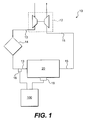
- Engine system 10 includes an intake air passageway 13 that leads to an engine 20.
- engine system 10 may include various components, such as, for example, a turbocharger 12 and an aftercooler 14.
- An exhaust air passageway 15 may lead from engine 20 to turbocharger 12.
- Engine 20 may be an internal combustion engine as illustrated in Fig. 2.
- engine 20 is depicted and described as a four stroke diesel engine.
- engine 20 may be any other type of internal combustion engine, such as, for example, a gasoline or natural gas engine.
- engine 20 includes an engine block 28 that defines a plurality of cylinders 22.
- a piston 24 is disposed for sliding movement between a top dead center position and a bottom dead center position within each cylinder 22.
- engine 20 includes six cylinders 22 and six associated pistons 24.
- engine 20 may include a greater or lesser number of pistons 24 and that pistons 24 may be disposed in an "in-line" configuration, a "V" configuration, or any other conventional configuration.
- engine 20 includes a crankshaft 27 that is rotatably disposed within engine block 28.
- a connecting rod 26 connects each piston 24 to crankshaft 27.
- Each piston 24 is coupled to crankshaft 27 so that a sliding motion of piston 24 within the respective cylinder 22 results in a rotation of crankshaft 27. Similarly, a rotation of crankshaft 27 will result in a sliding motion of piston 24.
- Engine 20 also includes a cylinder head 30.
- Cylinder head 30 defines an intake passageway 41 that leads to at least one intake port 36 for each cylinder 22. Cylinder head 30 may further define two or more intake ports 36 for each cylinder 22.
- An intake valve 32 is disposed within each intake port 36.
- Intake valve 32 includes a valve element 40 that is configured to selectively block intake port 36. As described in greater detail below, each intake valve 32 may be actuated to lift valve element 40 to thereby open the respective intake port 36.
- the intake valves 32 for each cylinder 22 may be actuated in unison or independently.
- Cylinder head 30 also defines at least one exhaust port 38 for each cylinder 22. Each exhaust port 38 leads from the respective cylinder 22 to an exhaust passageway 43. Cylinder head 30 may further define two or more exhaust ports 38 for each cylinder 22.
- An exhaust valve 34 is disposed within each exhaust port 38.
- Exhaust valve 34 includes a valve element 48 that is configured to selectively block exhaust port 38. As described in greater detail below, each exhaust valve 34 may be actuated to lift valve element 48 to thereby open the respective exhaust port 38.
- the exhaust valves 34 for each cylinder 22 may be actuated in unison or independently.
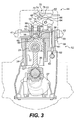
- Fig. 3 illustrates an exemplary embodiment of one cylinder 22 of engine 20.
- cylinder head 30 defines a pair of intake ports 36 connecting intake passageway 41 to cylinder 22.
- Each intake port 36 includes a valve seat 50.
- One intake valve 32 is disposed within each intake port 36.
- Valve element 40 of intake valve 32 is configured to engage valve seat 50. When intake valve 32 is in a closed position, valve element 40 engages valve seat 50 to close intake port 36 and blocks fluid flow relative to cylinder 22. When intake valve 32 is lifted from the closed position, intake valve 32 allows a flow of fluid relative to cylinder 22.
- cylinder head 30 may define two or more exhaust ports 38 (only one of which is illustrated in Fig. 2) that connect cylinder 22 with exhaust passageway 43.
- One exhaust valve 34 is disposed within each exhaust port 38.
- a valve element 48 of each exhaust valve 34 is configured to close exhaust port 38 when exhaust valve 34 is in a closed position and block fluid flow relative to cylinder 22.
- exhaust valve 34 When exhaust valve 34 is lifted from the closed position, exhaust valve 32 allows a flow of fluid relative to cylinder 22.
- engine 20 includes a series of valve actuation assemblies 44.
- One valve actuation assembly 44 may be operatively associated with each pair of intake valves 32 for each cylinder 22.
- Each valve actuation assembly 44 is operable to move or "lift" the associated intake valve 32 or exhaust valve 34 from a first, or closed, position to a second, or open, position.
- valve actuation assembly 44 includes a bridge 54 that is connected to each valve element 40 through a pair of valve stems 46.
- a spring 56 may be disposed around each valve stem 46 between cylinder head 30 and bridge 54. Spring 56 acts to bias both valve elements 40 into engagement with the respective valve seat 50 to thereby close each intake port 36.
- Valve actuation assembly 44 may also include a rocker arm 64.
- Rocker arm 64 is configured to pivot about a pivot 66.
- One end 68 of rocker arm 64 is connected to bridge 54.
- the opposite end of rocker arm 64 is connected to a cam assembly 52.
- cam assembly 52 includes a cam 60 having a cam lobe and mounted on a cam shaft, a push rod 61, and a cam follower 62.
- cam assembly 52 may have other configurations, such as, for example, where cam 60 acts directly on rocker arm 64.
- Valve actuation assembly 44 may be driven by cam 60.
- Cam 60 is connected to crankshaft 27 so that a rotation of crankshaft 27 induces a corresponding rotation of cam 60.
- Cam 60 may be connected to crankshaft 27 through any means readily apparent to one skilled in the art, such as, for example, through a gear reduction assembly (not shown).
- a rotation of cam 60 will cause cam follower 62 and associated push rod 61 to periodically reciprocate between an upper and a lower position.
- rocker arm 64 The reciprocating movement of push rod 61 causes rocker arm 64 to pivot about pivot 66.
- rocker arm 64 When push rod 61 moves in the direction indicated by arrow 58, rocker arm 64 will pivot and move bridge 54 in the opposite direction.
- the movement of bridge 54 causes each intake valve 32 to lift and open intake ports 36.
- springs 56 will act on bridge 54 to return each intake valve 32 to the closed position.
- cam 60 controls the timing of the actuation of intake valves 32.
- cam 60 may be configured to coordinate the actuation of intake valves 32 with the movement of piston 24.
- intake valves 32 may be actuated to open intake ports 36 when piston 24 is withdrawing within cylinder 22 to allow air to flow from intake passageway 41 into cylinder 22.
- a similar valve actuation assembly 44 may be connected to each pair of exhaust valves 34 for each cylinder 22.
- Either cam 60 or a second cam (not shown) may be connected to crankshaft 27 to control the actuation timing of exhaust valves 34.
- Exhaust valves 34 may be actuated to open exhaust ports 38 when piston 24 is advancing within cylinder 22 to allow exhaust to flow from cylinder 22 into exhaust passageway 43.
- valve actuation assembly 44 also includes a valve actuator 70.
- valve actuator 70 is hydraulically actuated. It should be understood that valve actuator 70 may be actuated through other types of systems, such as for example, electronic solenoids or other hydraulic systems.
- valve actuator 70 includes an actuator cylinder 72 that defines an actuator chamber 76.
- An actuator piston 74 is slidably disposed within actuator cylinder 72 and is connected to an actuator rod 78.
- a return spring (not shown) may act on actuator piston 74 to return actuator piston 74 to a home position.
- Actuator rod 78 is engageable with an end 68 of rocker arm 64.
- a fluid line 80 is connected to actuator chamber 76. Pressurized fluid may be directed through fluid line 80 into actuator chamber 76 to move actuator piston 74 within actuator cylinder 72. Movement of actuator piston 74 causes actuator rod 78 to engage end 68 of rocker arm 64.
- Fluid may be introduced to actuator chamber 76 when intake valves 32 are in the open position to move actuator rod 78 into engagement with rocker arm 64 to thereby hold intake valves 32 in the open position.
- fluid may be introduced to actuator chamber 76 when intake valves 32 are in the closed position to move actuator rod 78 into engagement with rocker arm 64 and pivot rocker arm 64 about pivot 66 to thereby open intake valves 32.
- a source of hydraulic fluid 84 is provided to draw fluid from a tank 87 and to supply pressurized fluid to valve actuator 70.
- Source of hydraulic fluid 84 may be part of a lubrication system, such as typically accompanies an internal combustion engine.
- a lubrication system may provide pressurized fluid having a pressure of, for example, less than 700 KPa (100 psi) or, more particularly, between about 210 KPa and 620 KPa (30 psi and 90 psi).
- the source of hydraulic fluid may be a pump configured to provide fluid at a higher pressure, such as, for example, between about 10 MPa and 35 MPa (1450 psi and 5000 psi).
- a fluid supply system 79 connects source of hydraulic fluid 84 with valve actuator 70.
- source of hydraulic fluid 84 is connected to a fluid rail 86 through fluid line 85.
- a control valve 82 is disposed in fluid line 85. Control valve 82 may be opened to allow pressurized fluid to flow from source of hydraulic fluid 84 to fluid rail 86. Control valve 82 may be closed to prevent pressurized fluid from flowing from source of hydraulic fluid 84 to fluid rail 86.
- fluid rail 86 supplies pressurized fluid from source of hydraulic fluid 84 to a series of valve actuators 70.
- Each valve actuator 70 may be associated with either the intake valves 32 or the exhaust valves 34 of a particular engine cylinder 22 (referring to Fig. 1).
- Fluid lines 80 direct pressurized fluid from fluid rail 86 into the actuator chamber 76 of each valve actuator 70.
- a directional control valve 88 may be disposed in each fluid line 80. Each directional control valve 88 may be opened to allow pressurized fluid to flow between fluid rail 86 and actuator chamber 76. Each directional control valve 88 may be closed to prevent pressurized fluid from flowing between fluid rail 86 and actuator chamber 76. Directional control valve 88 may be normally biased into a closed position and actuated to allow fluid to flow through directional control valve 88. Alternatively, directional control valve 88 may be normally biased into an open position and actuated to prevent fluid from flowing through directional control valve 88.
- directional control valve 88 may be any type of controllable valve, such as, for example a two coil latching valve.
- fluid supply system 79 may have a variety of different configurations and include a variety of different components.
- fluid supply system 79 may include a check valve placed in parallel with directional control valve 88 between control valve 82 and hydraulic actuator 70.
- fluid supply system 79 may include a source of high pressure fluid.
- Fluid supply system 79 may also include a snubbing valve to control the rate of fluid flow from hydraulic actuator 70 and a damping system, which may include an accumulator and a restricted orifice, to prevent pressure oscillations in actuator chamber 76 and fluid line 80.
- Controller 100 is connected to each valve actuation assembly 44 and to control valve 82.
- Controller 100 may include an electronic control module that has a microprocessor and a memory 101.
- the memory is connected to the microprocessor and stores an instruction set and variables.
- various other known circuits such as, for example, power supply circuitry, signal conditioning circuitry, and solenoid driver circuitry, among others.
- Controller 100 may be programmed to control one or more aspects of the operation of engine 20.
- controller 100 may be programmed to control valve actuation assembly 44, the fuel injection system, and any other engine function commonly controlled by an electronic control module.
- Controller 100 may control engine 20 based on the current operating conditions of the engine and/or instructions received from an operator.
- Controller 100 may control valve actuation assembly 44 by transmitting a signal, such as, for example, a current, to directional control valve 88.
- the transmitted signal may result in the selective opening and/or closing of directional control valve 88. If directional control valve 88 is a normally closed valve, the transmitted signal may cause directional control valve 88 to open for a certain period of time. If directional control valve 88 is a normally open valve, the transmitted signal may cause directional control valve to close for a certain period of time.
- controller may control the flow of fluid to and from valve actuator 70 and thereby control the engagement of actuator rod 78 with rocker arm 64 to delay the closing of intake valve 32 for a predetermined period.
- An exemplary intake valve actuation 104 is illustrated in Fig. 5.
- engine system 10 may include a series of sensors, which are described in greater detail below. Each sensor is configured to monitor a particular operating parameter of engine 20. One skilled in the art may recognize that alternative sensors may be used with engine system 10 to monitor other operating parameters of engine 20.
- an intake sensor 16 may be disposed in intake passageway 13.
- Intake sensor 16 may be configured to sense the pressure of the intake air and/or the mass flow rate of the intake air.
- Intake sensor 16 may be any type of sensor readily apparent to one skilled in the art as capable of sensing these types of parameters and may be disposed at any point along intake passageway 13.
- At least one engine sensor 18 is operatively connected with engine 20.
- Engine sensor 18 may be any type of sensor commonly used to monitor an operating parameter of engine 20.
- engine sensor 18 may be configured to sense the load on engine 20, the amount of fuel being supplied to engine 20, the rotational speed of engine 20, the pressure within one or more cylinders 22, the rotational angle of crankshaft 27, or any other commonly sensed operating parameter.
- Engine sensor 18 may be any type of sensor readily apparent to one skilled in the art as capable of sensing these types of engine operating parameters.
- Memory 101 of controller 100 may store information related to the operation of engine 20 in the form of a "map."
- the term "map" is intended to include any electronic storage structure for storing information related to the operation of the engine, such as, for example, data tables, look-up tables, graphs, or any other electronic storage format readily apparent to one skilled in the art.
- These maps may define optimal engine operating characteristics as a function of engine operating parameters.
- memory 101 may store a map that defines an optimal valve actuation period for a particular engine speed and load.
- memory 101 may store a map that defines an optimal fuel delivery rate for a particular engine speed and load.
- Memory 101 may also store a map that defines an optimal air fuel ratio for a particular engine speed and load.
- Memory 101 may further store a map that defines limits on the valve actuation period for a particular engine speed and engine load.
- Memory 101 may store different versions or variations on each of these maps. For example, memory 101 may store one valve actuation period map that provides optimal operating characteristics for steady state engine operation. Memory 101 may store a second valve actuation period map that provide optimal operating characteristics for transient conditions, where the engine load and/or the engine speed are changing. One skilled in the art may recognize that memory 101 may store additional maps or other variations that define other engine operating characteristics based on these, or other, operating parameters.
- Controller 100 may use the information provided by the sensors to access the maps stored in memory 101 to identify an optimal intake valve actuation period for the current engine operating conditions.
- the flowchart of Fig. 6 illustrates an exemplary method of determining an optimal intake valve actuation period.
- Controller 100 may selectively operate valve actuator 70 to implement a late intake type Miller cycle in engine 20.
- controller 100 operates valve actuator 70 to delay the closing of intake valve 32 from a conventional closing, where the closing substantially coincides with the end of an intake stroke, to a delayed closing, where intake valve 32 is held open for a predetermined portion of a compression stroke.
- the duration of the intake valve actuation period may be determined based on the current operating conditions of engine 20.
- cam assembly 52 controls the initial actuation timing of intake valves 32.
- controller 100 ensures control valve 82 and directional control valve 88 are in an open position. This allows pressurized fluid to flow from source of hydraulic fluid 84 through fluid rail 86 and into actuator chamber 76.
- the force of the fluid entering actuator chamber 76 moves actuator piston 74 so that actuator rod 78 follows end 68 of rocker arm 64 as rocker arm 64 pivots to open intake valves 32.
- the distance and rate of movement of actuator rod 78 will depend upon the configuration of actuator chamber 76 and fluid supply system 79.
- Fluid supply system 79 may be configured to provide a sufficient flow of fluid to actuator chamber 76 to ensure that actuator chamber 76 is filled with fluid before cam 60 returns intake valve 32 to the closed position.
- Controller 100 may actuate valve actuator 70 by closing directional control valve 88. This prevents fluid from escaping from actuator chamber 76. As cam 60 continues to rotate and springs 56 urge intake valves 32 towards the closed position, actuator rod 78 will engage end 68 of rocker arm and prevent intake valves 32 from closing. As long as directional control valve 88 remains in the closed position, the trapped fluid in actuator chamber 76 will prevent springs 56 from returning intake valves 32 to the closed position. Thus, valve actuator 70 will hold intake valves 32 in the open position, independently of the action of cam assembly 52.
- Controller 100 may disengage valve actuator 70 to allow intake valves 32 to close by opening directional control valve 88. This allows the pressurized fluid to flow out of actuator chamber 76. The force of springs 56 forces the fluid from actuator chamber 76, thereby allowing actuator piston 74 to move within actuator cylinder 72. This allows rocker arm 64 to pivot so that intake valves 32 are moved to the closed position.
- valve actuator 70 may extend intake valve actuation 104 from a conventional closing 110 to a delayed closing 108.
- the period, or duration, of the extended intake valve actuation may be measured in terms of the angle of rotation of crankshaft 27, as a function of time, or in any other manner readily apparent to one skilled in the art.
- the extended intake valve actuation period may be between about 0° and 120° crankshaft rotation.
- valve actuator 70 may be used to implement other types of valve actuation timing variations, such as, for example, engine braking.
- Controller 100 may vary the intake valve actuation period based upon the operating conditions that engine 20 is experiencing. For example, when engine 20 is operating in a steady state condition and is experiencing a light load, the optimal duration of the valve actuation period may be shorter than when engine 20 is operating under a steady state condition and is experiencing an increased load, such as a heavy load acceleration. When engine 20 is operating in a steady state condition, the optimal duration of the valve actuation period may increase as the load on the engine increases.
- controller 100 may determine the valve actuation period by sensing the current engine speed and load and accessing a map stored in memory 101.
- the map may set forth the desired valve actuation period for a series of different engine speeds and loads. Based on the information provided in this map, controller 100 may control valve actuator 70 to achieve the desired valve actuation period.
- controller 100 may receive an indication of the engine speed and the load from engine sensor(s) 18 and an indication of the intake air pressure from intake sensor 16.
- controller 100 determines if engine 20 is operating in a steady state condition or a transient condition. (Step 122). Controller 100 may make this determination based on a comparison between the current values of the sensed operating parameters and previous values of the operating parameters. For example, an increase in the engine speed or engine load may indicate that engine 20 is experiencing a transient condition.
- Controller 100 may make this determination based on a comparison between the current values of the sensed operating parameters and previous values of the operating parameters. For example, an increase in the engine speed or engine load may indicate that engine 20 is experiencing a transient condition.
- various parameters and analysis may be used to make this determination.
- Controller 100 may determine the desired air fuel ratio and the desired fuel rate for the current operating conditions. If engine 20 is operating in a steady state mode, controller 100 may access maps that define the optimal air fuel ratio and fuel rate for the current steady state conditions. (Steps 124 and 126). Alternatively, if engine 20 is operating in a transient condition, controller 100 may access maps that define the optimal air fuel ratio and fuel rate for the current transient operating conditions.
- Controller 100 may then determine if there are any limits on the valve actuation period. (Step 132).
- the valve actuation period may be limited to control the amount of emissions generated by engine 20 and/or to prevent damage to engine 20.
- a significant decrease in the valve actuation period may result in an increase in the compression ratio and maximum pressure within each cylinder 22. The increase in pressure in each cylinder 22 may damage engine 20.
- valve actuation period may be stored in a map in memory 101.
- the map may be based on engine parameters, such as engine speed and engine load, or any other conditions apparent on one skilled in the art. Controller 100 may access this map to determine the limits on the valve actuation period for the current operating conditions of engine 20.
- Controller 100 also calculates the desired airflow for the operating conditions. (Step 134).
- the desired airflow may be calculated by multiplying the fuel rate (as determined in step 126 or step 130) by the air fuel ratio (as determined in step 124 or step 128).
- the Controller 100 may then calculate the intake valve actuation period. (Step 136).
- the intake valve actuation period may be expressed as a function of the engine speed (ES), the intake air pressure (IP), and the desired airflow (AF).
- A, B, C, D, E, F, G, and H are constants.
- the above formula will yield an intake valve actuation period, P, that is expressed in terms of an engine crank angle.
- the determined crank angle may represent the angle at which the current to directional control valve 88 should be terminated to open directional control valve 88 and release valve actuator 70.
- the determined crank angle may represent the angle at which intake valve actuator 70 should be returned to the closed position.
- controller 100 may then determine the engine crank angle at which to terminate the current to directional control valve 88 based on a constant that is indicative of the time required for the intake valve 32 to close after the current to directional control valve 88 has been terminated.
- valve actuation period may be expressed as an amount of a rotation of crankshaft or a time period.
- Controller 100 may then compare the calculated valve actuation period with any limits on the valve actuation period. (Step 138). If the calculated valve actuation period would exceed any limitations and subject engine 20 to possible damage, controller 100 will use the limited valve actuation period, as determined in Step 132. (Step 140). If the calculated valve actuation period would not exceed any limitation, controller 100 will use the calculated valve actuation period. (Step 142).
- Controller 100 may then control directional control valve 88 to actuate valve actuator 70 to achieve the desired valve actuation period. Controller 100 may continuously monitor the operating parameters of engine 20 and adjust the valve actuation period accordingly. In this manner, controller 100 may optimize the air fuel ratio based on the current operating conditions of engine 20.
- the present invention provides a method and system for controlling a variable valve actuation assembly for an internal combustion engine. This provides for the optimization of the air fuel ratio supplied to the engine based on the operating conditions of the engine.
- the air fuel ratio may be optimized to improve the performance of the engine and/or reduce the amount of emissions generated by the engine.
Abstract
Description
- The present invention is directed to a system and method for controlling a variable valve actuation system. More particularly, the present invention is directed to a system and method for controlling a variable valve actuation system in an internal combustion engine.
- Fuel efficiency and emission reductions are a concern in the design and operation of an internal combustion engine, such as, for example, a diesel, gasoline, or natural gas engine. Accordingly, a significant amount of research and development work is being directed towards reducing the emissions while maintaining or improving the fuel efficiency of these types of engines. Any increase in fuel efficiency will directly translate to a reduction in the fuel costs associated with operating the engine along with the production of carbon dioxide.
- Oxides of nitrogen ("NOx") are another constituent of engine emissions that researchers are trying to reduce. NOx production is generally proportional to temperatures of combustion and volume of excess air. Unfortunately, fuel efficiency also is generally proportional to these same factors. Conventional NOx reduction techniques include increasing the mass of inert matter, such as water or recirculated exhaust gas, in a combustion chamber prior to combusting a fuel air mixture. These measures may reduce the temperature of combustion and may also reduce the fuel efficiency.
- One possible approach to improving fuel efficiency involves improving control over the flow of gases into and out of the engine. This may be accomplished by modifying the typical engine valve actuation system to provide flexibility in the actuation timing of the intake and exhaust valves. This may allow the flow of gases to and from the engine to be tailored to meet the particular operating conditions of the engine.
- The engine valves in an internal combustion engine are typically driven by a cam arrangement that is operatively connected to the crankshaft of the engine. The rotation of the crankshaft results in a corresponding rotation of a cam that drives one or more cam followers. The movement of the cam followers results in the actuation of the engine valves. The shape of the cam governs the timing and duration of the valve actuation.
- An engine may, however, include a variable valve actuation system, such as described in U.S. Patent No. 6,237,551 to Macor et al., issued on 29 May 2001. In this type of system, the cam arrangement is configured to hold the engine valves open for a certain period of time and an auxiliary valve is included to selectively disengage the cam assembly. This allows the engine valves to be closed earlier than provided by the timing of the cam assembly and improves the control over valve actuation timing.
- The improved control provided by a variable valve actuation system may allow for gains in fuel efficiency. The variable valve actuation system may be operated to selectively implement a variation on the typical diesel or Otto cycle during the operation of the engine. For example, the intake valves may be controlled to implement a "late intake" type Miller cycle. In a late intake Miller cycle, the intake valves are opened for the intake stroke and held open for a portion of the compression stroke of the piston.
- The implementation of such an actuation timing variation may, however, have a detrimental effect on the performance of the engine under certain operating conditions. For example, the implementation of a late intake Miller cycle may reduce the compression ratio within the combustion chambers and reduce the amount of air flow through the engine. The reduced compression ratio and air flow may negatively impact the performance of the engine when the engine is subject to a load increase, such as, for example, an acceleration.
- The system and method of the present invention solves one or more of the problems set forth above.
- In one aspect, the present invention is directed to a method of controlling a variable valve actuation system. A cam assembly is operated to move an intake valve between a first position where the intake valve blocks a flow of fluid and a second position where the intake valve allows a flow of fluid. At least one operating parameter of the engine is sensed. A valve actuation period is determined based on the at least one operating parameter. A valve actuator is engaged with the intake valve to prevent the intake valve from returning to the first position in response to operation of the cam assembly. The valve actuator is released to allow the intake valve to return to the first position at the end of the determined valve actuation period.
- In another aspect, the present invention is directed to an intake valve actuation system for an engine. An intake valve is moveable between a first position where the intake valve prevents a flow of fluid and a second position where the intake valve allows a flow of fluid. A cam assembly is connected to the intake valve to move the intake valve between the first position and the second position. A valve actuator is selectively operable to engage the intake valve and prevent the intake valve from returning to the first position. A sensor is operable to sense an operating parameter of the engine. A controller is operable to determine a valve actuation period based on the sensed parameter of the engine.
-
- Fig. 1 is a diagrammatic and schematic representation of an engine system in accordance with an exemplary embodiment of the present invention;
- Fig. 2 is a diagrammatic cross-sectional view of an internal combustion engine in accordance with an exemplary embodiment of the present invention;
- Fig. 3 is a diagrammatic cross-sectional view of a cylinder and valve actuation assembly in accordance with an exemplary embodiment of the present invention;
- Fig. 4 is a schematic and diagrammatic representation of a fluid supply system for a hydraulic actuator for an engine valve in accordance with an exemplary embodiment of the present invention;
- Fig. 5 is a graphic illustration of an exemplary intake valve actuation in accordance with the present invention; and
- Fig. 6 is a flowchart illustrating an exemplary method for controlling a variable valve actuation system in accordance with the present invention.
-
- Reference will now be made in detail to exemplary embodiments of the invention, which are illustrated in the accompanying drawings. Wherever possible, the same reference numbers will be used throughout the drawings to refer to the same or like parts.
- An exemplary embodiment of an
engine system 10 is illustrated in Fig. 1.Engine system 10 includes anintake air passageway 13 that leads to anengine 20. One skilled in the art will recognize thatengine system 10 may include various components, such as, for example, aturbocharger 12 and anaftercooler 14. Anexhaust air passageway 15 may lead fromengine 20 to turbocharger 12. -
Engine 20 may be an internal combustion engine as illustrated in Fig. 2. For the purposes of the present disclosure,engine 20 is depicted and described as a four stroke diesel engine. One skilled in the art will recognize, however, thatengine 20 may be any other type of internal combustion engine, such as, for example, a gasoline or natural gas engine. - As illustrated in Fig. 2,
engine 20 includes anengine block 28 that defines a plurality ofcylinders 22. Apiston 24 is disposed for sliding movement between a top dead center position and a bottom dead center position within eachcylinder 22. In the illustrated embodiment,engine 20 includes sixcylinders 22 and six associatedpistons 24. One skilled in the art will recognize thatengine 20 may include a greater or lesser number ofpistons 24 and thatpistons 24 may be disposed in an "in-line" configuration, a "V" configuration, or any other conventional configuration. - As also shown in Fig. 2,
engine 20 includes acrankshaft 27 that is rotatably disposed withinengine block 28. A connectingrod 26 connects eachpiston 24 tocrankshaft 27. Eachpiston 24 is coupled tocrankshaft 27 so that a sliding motion ofpiston 24 within therespective cylinder 22 results in a rotation ofcrankshaft 27. Similarly, a rotation ofcrankshaft 27 will result in a sliding motion ofpiston 24. -
Engine 20 also includes acylinder head 30.Cylinder head 30 defines anintake passageway 41 that leads to at least oneintake port 36 for eachcylinder 22.Cylinder head 30 may further define two ormore intake ports 36 for eachcylinder 22. - An
intake valve 32 is disposed within eachintake port 36.Intake valve 32 includes avalve element 40 that is configured to selectively blockintake port 36. As described in greater detail below, eachintake valve 32 may be actuated to liftvalve element 40 to thereby open therespective intake port 36. Theintake valves 32 for eachcylinder 22 may be actuated in unison or independently. -
Cylinder head 30 also defines at least oneexhaust port 38 for eachcylinder 22. Eachexhaust port 38 leads from therespective cylinder 22 to anexhaust passageway 43.Cylinder head 30 may further define two ormore exhaust ports 38 for eachcylinder 22. - An
exhaust valve 34 is disposed within eachexhaust port 38.Exhaust valve 34 includes avalve element 48 that is configured to selectively blockexhaust port 38. As described in greater detail below, eachexhaust valve 34 may be actuated to liftvalve element 48 to thereby open therespective exhaust port 38. Theexhaust valves 34 for eachcylinder 22 may be actuated in unison or independently. - Fig. 3 illustrates an exemplary embodiment of one
cylinder 22 ofengine 20. As shown,cylinder head 30 defines a pair ofintake ports 36 connectingintake passageway 41 tocylinder 22. Eachintake port 36 includes avalve seat 50. Oneintake valve 32 is disposed within eachintake port 36.Valve element 40 ofintake valve 32 is configured to engagevalve seat 50. Whenintake valve 32 is in a closed position,valve element 40 engagesvalve seat 50 to closeintake port 36 and blocks fluid flow relative tocylinder 22. Whenintake valve 32 is lifted from the closed position,intake valve 32 allows a flow of fluid relative tocylinder 22. - Similarly,
cylinder head 30 may define two or more exhaust ports 38 (only one of which is illustrated in Fig. 2) that connectcylinder 22 withexhaust passageway 43. Oneexhaust valve 34 is disposed within eachexhaust port 38. Avalve element 48 of eachexhaust valve 34 is configured to closeexhaust port 38 whenexhaust valve 34 is in a closed position and block fluid flow relative tocylinder 22. Whenexhaust valve 34 is lifted from the closed position,exhaust valve 32 allows a flow of fluid relative tocylinder 22. - As shown in Fig. 2,
engine 20 includes a series ofvalve actuation assemblies 44. Onevalve actuation assembly 44 may be operatively associated with each pair ofintake valves 32 for eachcylinder 22. Eachvalve actuation assembly 44 is operable to move or "lift" the associatedintake valve 32 orexhaust valve 34 from a first, or closed, position to a second, or open, position. - In the exemplary embodiment of Fig. 3,
valve actuation assembly 44 includes abridge 54 that is connected to eachvalve element 40 through a pair of valve stems 46. Aspring 56 may be disposed around each valve stem 46 betweencylinder head 30 andbridge 54.Spring 56 acts to bias bothvalve elements 40 into engagement with therespective valve seat 50 to thereby close eachintake port 36. -
Valve actuation assembly 44 may also include arocker arm 64.Rocker arm 64 is configured to pivot about apivot 66. Oneend 68 ofrocker arm 64 is connected to bridge 54. The opposite end ofrocker arm 64 is connected to acam assembly 52. In the exemplary embodiment of Fig. 3,cam assembly 52 includes acam 60 having a cam lobe and mounted on a cam shaft, apush rod 61, and acam follower 62. One skilled in the art will recognize thatcam assembly 52 may have other configurations, such as, for example, wherecam 60 acts directly onrocker arm 64. -
Valve actuation assembly 44 may be driven bycam 60.Cam 60 is connected to crankshaft 27 so that a rotation ofcrankshaft 27 induces a corresponding rotation ofcam 60.Cam 60 may be connected to crankshaft 27 through any means readily apparent to one skilled in the art, such as, for example, through a gear reduction assembly (not shown). As one skilled in the art will recognize, a rotation ofcam 60 will causecam follower 62 and associatedpush rod 61 to periodically reciprocate between an upper and a lower position. - The reciprocating movement of
push rod 61 causesrocker arm 64 to pivot aboutpivot 66. Whenpush rod 61 moves in the direction indicated byarrow 58,rocker arm 64 will pivot and movebridge 54 in the opposite direction. The movement ofbridge 54 causes eachintake valve 32 to lift andopen intake ports 36. Ascam 60 continues to rotate, springs 56 will act onbridge 54 to return eachintake valve 32 to the closed position. - In this manner, the shape and orientation of
cam 60 controls the timing of the actuation ofintake valves 32. As one skilled in the art will recognize,cam 60 may be configured to coordinate the actuation ofintake valves 32 with the movement ofpiston 24. For example,intake valves 32 may be actuated to openintake ports 36 whenpiston 24 is withdrawing withincylinder 22 to allow air to flow fromintake passageway 41 intocylinder 22. - A similar
valve actuation assembly 44 may be connected to each pair ofexhaust valves 34 for eachcylinder 22. Eithercam 60 or a second cam (not shown) may be connected to crankshaft 27 to control the actuation timing ofexhaust valves 34.Exhaust valves 34 may be actuated to openexhaust ports 38 whenpiston 24 is advancing withincylinder 22 to allow exhaust to flow fromcylinder 22 intoexhaust passageway 43. - As shown in Fig. 3,
valve actuation assembly 44 also includes avalve actuator 70. In the illustrated exemplary embodiment,valve actuator 70 is hydraulically actuated. It should be understood thatvalve actuator 70 may be actuated through other types of systems, such as for example, electronic solenoids or other hydraulic systems. - In the illustrated exemplary embodiment,
valve actuator 70 includes an actuator cylinder 72 that defines an actuator chamber 76. An actuator piston 74 is slidably disposed within actuator cylinder 72 and is connected to anactuator rod 78. A return spring (not shown) may act on actuator piston 74 to return actuator piston 74 to a home position.Actuator rod 78 is engageable with anend 68 ofrocker arm 64. - A
fluid line 80 is connected to actuator chamber 76. Pressurized fluid may be directed throughfluid line 80 into actuator chamber 76 to move actuator piston 74 within actuator cylinder 72. Movement of actuator piston 74 causes actuatorrod 78 to engageend 68 ofrocker arm 64. - Fluid may be introduced to actuator chamber 76 when
intake valves 32 are in the open position to moveactuator rod 78 into engagement withrocker arm 64 to thereby holdintake valves 32 in the open position.
Alternatively, fluid may be introduced to actuator chamber 76 whenintake valves 32 are in the closed position to moveactuator rod 78 into engagement withrocker arm 64 andpivot rocker arm 64 aboutpivot 66 to thereby openintake valves 32. - As illustrated in Figs. 2 and 4, a source of
hydraulic fluid 84 is provided to draw fluid from atank 87 and to supply pressurized fluid tovalve actuator 70. Source ofhydraulic fluid 84 may be part of a lubrication system, such as typically accompanies an internal combustion engine. Such a lubrication system may provide pressurized fluid having a pressure of, for example, less than 700 KPa (100 psi) or, more particularly, between about 210 KPa and 620 KPa (30 psi and 90 psi). Alternatively, the source of hydraulic fluid may be a pump configured to provide fluid at a higher pressure, such as, for example, between about 10 MPa and 35 MPa (1450 psi and 5000 psi). - A
fluid supply system 79 connects source ofhydraulic fluid 84 withvalve actuator 70. In the exemplary embodiment of Fig. 4, source ofhydraulic fluid 84 is connected to afluid rail 86 throughfluid line 85. Acontrol valve 82 is disposed influid line 85.Control valve 82 may be opened to allow pressurized fluid to flow from source ofhydraulic fluid 84 tofluid rail 86.Control valve 82 may be closed to prevent pressurized fluid from flowing from source ofhydraulic fluid 84 tofluid rail 86. - As illustrated in Fig. 4,
fluid rail 86 supplies pressurized fluid from source ofhydraulic fluid 84 to a series ofvalve actuators 70. Eachvalve actuator 70 may be associated with either theintake valves 32 or theexhaust valves 34 of a particular engine cylinder 22 (referring to Fig. 1).Fluid lines 80 direct pressurized fluid fromfluid rail 86 into the actuator chamber 76 of eachvalve actuator 70. - A
directional control valve 88 may be disposed in eachfluid line 80. Eachdirectional control valve 88 may be opened to allow pressurized fluid to flow betweenfluid rail 86 and actuator chamber 76. Eachdirectional control valve 88 may be closed to prevent pressurized fluid from flowing betweenfluid rail 86 and actuator chamber 76.Directional control valve 88 may be normally biased into a closed position and actuated to allow fluid to flow throughdirectional control valve 88. Alternatively,directional control valve 88 may be normally biased into an open position and actuated to prevent fluid from flowing throughdirectional control valve 88. One skilled in the art will recognize thatdirectional control valve 88 may be any type of controllable valve, such as, for example a two coil latching valve. - One skilled in the art will recognize that
fluid supply system 79 may have a variety of different configurations and include a variety of different components. For example,fluid supply system 79 may include a check valve placed in parallel withdirectional control valve 88 betweencontrol valve 82 andhydraulic actuator 70. In addition,fluid supply system 79 may include a source of high pressure fluid.Fluid supply system 79 may also include a snubbing valve to control the rate of fluid flow fromhydraulic actuator 70 and a damping system, which may include an accumulator and a restricted orifice, to prevent pressure oscillations in actuator chamber 76 andfluid line 80. - As shown in Fig. 2, a
controller 100 is connected to eachvalve actuation assembly 44 and to controlvalve 82.Controller 100 may include an electronic control module that has a microprocessor and amemory 101. As is known to those skilled in the art, the memory is connected to the microprocessor and stores an instruction set and variables. Associated with the microprocessor and part of electronic control module are various other known circuits such as, for example, power supply circuitry, signal conditioning circuitry, and solenoid driver circuitry, among others. -
Controller 100 may be programmed to control one or more aspects of the operation ofengine 20. For example,controller 100 may be programmed to controlvalve actuation assembly 44, the fuel injection system, and any other engine function commonly controlled by an electronic control module.Controller 100 may controlengine 20 based on the current operating conditions of the engine and/or instructions received from an operator. -
Controller 100 may controlvalve actuation assembly 44 by transmitting a signal, such as, for example, a current, todirectional control valve 88. The transmitted signal may result in the selective opening and/or closing ofdirectional control valve 88. Ifdirectional control valve 88 is a normally closed valve, the transmitted signal may causedirectional control valve 88 to open for a certain period of time. Ifdirectional control valve 88 is a normally open valve, the transmitted signal may cause directional control valve to close for a certain period of time. By controlling the opening and closing ofdirectional control valve 88, controller may control the flow of fluid to and fromvalve actuator 70 and thereby control the engagement ofactuator rod 78 withrocker arm 64 to delay the closing ofintake valve 32 for a predetermined period. An exemplaryintake valve actuation 104 is illustrated in Fig. 5. - As illustrated in Figs. 1-4,
engine system 10 may include a series of sensors, which are described in greater detail below. Each sensor is configured to monitor a particular operating parameter ofengine 20. One skilled in the art may recognize that alternative sensors may be used withengine system 10 to monitor other operating parameters ofengine 20. - As shown in Fig. 1, an
intake sensor 16 may be disposed inintake passageway 13.Intake sensor 16 may be configured to sense the pressure of the intake air and/or the mass flow rate of the intake air.Intake sensor 16 may be any type of sensor readily apparent to one skilled in the art as capable of sensing these types of parameters and may be disposed at any point alongintake passageway 13. - As also shown in Fig. 1, at least one
engine sensor 18 is operatively connected withengine 20.Engine sensor 18 may be any type of sensor commonly used to monitor an operating parameter ofengine 20. For example,engine sensor 18 may be configured to sense the load onengine 20, the amount of fuel being supplied toengine 20, the rotational speed ofengine 20, the pressure within one ormore cylinders 22, the rotational angle ofcrankshaft 27, or any other commonly sensed operating parameter.Engine sensor 18 may be any type of sensor readily apparent to one skilled in the art as capable of sensing these types of engine operating parameters. -
Memory 101 ofcontroller 100 may store information related to the operation ofengine 20 in the form of a "map." For the purposes of the present disclosure, the term "map" is intended to include any electronic storage structure for storing information related to the operation of the engine, such as, for example, data tables, look-up tables, graphs, or any other electronic storage format readily apparent to one skilled in the art. These maps may define optimal engine operating characteristics as a function of engine operating parameters. For example,memory 101 may store a map that defines an optimal valve actuation period for a particular engine speed and load. Similarly,memory 101 may store a map that defines an optimal fuel delivery rate for a particular engine speed and load.Memory 101 may also store a map that defines an optimal air fuel ratio for a particular engine speed and load.Memory 101 may further store a map that defines limits on the valve actuation period for a particular engine speed and engine load. -
Memory 101 may store different versions or variations on each of these maps. For example,memory 101 may store one valve actuation period map that provides optimal operating characteristics for steady state engine operation.Memory 101 may store a second valve actuation period map that provide optimal operating characteristics for transient conditions, where the engine load and/or the engine speed are changing. One skilled in the art may recognize thatmemory 101 may store additional maps or other variations that define other engine operating characteristics based on these, or other, operating parameters. -
Controller 100 may use the information provided by the sensors to access the maps stored inmemory 101 to identify an optimal intake valve actuation period for the current engine operating conditions. The flowchart of Fig. 6 illustrates an exemplary method of determining an optimal intake valve actuation period. -
Controller 100 may selectively operatevalve actuator 70 to implement a late intake type Miller cycle inengine 20. When operating under the late intake Miller cycle,controller 100 operatesvalve actuator 70 to delay the closing ofintake valve 32 from a conventional closing, where the closing substantially coincides with the end of an intake stroke, to a delayed closing, whereintake valve 32 is held open for a predetermined portion of a compression stroke. The duration of the intake valve actuation period may be determined based on the current operating conditions ofengine 20. - As described above,
cam assembly 52 controls the initial actuation timing ofintake valves 32. Ascam 60 and pushrod 61 start to pivotrocker arm 64,controller 100 ensurescontrol valve 82 anddirectional control valve 88 are in an open position. This allows pressurized fluid to flow from source ofhydraulic fluid 84 throughfluid rail 86 and into actuator chamber 76. The force of the fluid entering actuator chamber 76 moves actuator piston 74 so thatactuator rod 78 followsend 68 ofrocker arm 64 asrocker arm 64 pivots to openintake valves 32. The distance and rate of movement ofactuator rod 78 will depend upon the configuration of actuator chamber 76 andfluid supply system 79.Fluid supply system 79 may be configured to provide a sufficient flow of fluid to actuator chamber 76 to ensure that actuator chamber 76 is filled with fluid beforecam 60 returnsintake valve 32 to the closed position. -
Controller 100 may actuatevalve actuator 70 by closingdirectional control valve 88. This prevents fluid from escaping from actuator chamber 76. Ascam 60 continues to rotate and springs 56urge intake valves 32 towards the closed position,actuator rod 78 will engage end 68 of rocker arm and preventintake valves 32 from closing. As long asdirectional control valve 88 remains in the closed position, the trapped fluid in actuator chamber 76 will preventsprings 56 from returningintake valves 32 to the closed position. Thus,valve actuator 70 will holdintake valves 32 in the open position, independently of the action ofcam assembly 52. -
Controller 100 may disengagevalve actuator 70 to allowintake valves 32 to close by openingdirectional control valve 88. This allows the pressurized fluid to flow out of actuator chamber 76. The force ofsprings 56 forces the fluid from actuator chamber 76, thereby allowing actuator piston 74 to move within actuator cylinder 72. This allowsrocker arm 64 to pivot so thatintake valves 32 are moved to the closed position. - As illustrated in Fig. 5, operation of
valve actuator 70 may extendintake valve actuation 104 from aconventional closing 110 to a delayedclosing 108. The period, or duration, of the extended intake valve actuation may be measured in terms of the angle of rotation ofcrankshaft 27, as a function of time, or in any other manner readily apparent to one skilled in the art. When implementing a late intake type Miller cycle, the extended intake valve actuation period may be between about 0° and 120° crankshaft rotation. One skilled in the art will recognize, however, thatvalve actuator 70 may be used to implement other types of valve actuation timing variations, such as, for example, engine braking. -
Controller 100 may vary the intake valve actuation period based upon the operating conditions thatengine 20 is experiencing. For example, whenengine 20 is operating in a steady state condition and is experiencing a light load, the optimal duration of the valve actuation period may be shorter than whenengine 20 is operating under a steady state condition and is experiencing an increased load, such as a heavy load acceleration. Whenengine 20 is operating in a steady state condition, the optimal duration of the valve actuation period may increase as the load on the engine increases. - In one exemplary method,
controller 100 may determine the valve actuation period by sensing the current engine speed and load and accessing a map stored inmemory 101. The map may set forth the desired valve actuation period for a series of different engine speeds and loads. Based on the information provided in this map,controller 100 may controlvalve actuator 70 to achieve the desired valve actuation period. - An alternative method of determining the intake valve actuation period is illustrated in the flowchart of Fig. 6. One or more operating parameters of
engine 20 are sensed. (Step 120). For example,controller 100 may receive an indication of the engine speed and the load from engine sensor(s) 18 and an indication of the intake air pressure fromintake sensor 16. - Based on the operating parameter(s) of
engine 20,controller 100 determines ifengine 20 is operating in a steady state condition or a transient condition. (Step 122).Controller 100 may make this determination based on a comparison between the current values of the sensed operating parameters and previous values of the operating parameters. For example, an increase in the engine speed or engine load may indicate thatengine 20 is experiencing a transient condition. One skilled in the art will recognize that various parameters and analysis may be used to make this determination. -
Controller 100 may determine the desired air fuel ratio and the desired fuel rate for the current operating conditions. Ifengine 20 is operating in a steady state mode,controller 100 may access maps that define the optimal air fuel ratio and fuel rate for the current steady state conditions. (Steps 124 and 126). Alternatively, ifengine 20 is operating in a transient condition,controller 100 may access maps that define the optimal air fuel ratio and fuel rate for the current transient operating conditions. -
Controller 100 may then determine if there are any limits on the valve actuation period. (Step 132). The valve actuation period may be limited to control the amount of emissions generated byengine 20 and/or to prevent damage toengine 20. A significant decrease in the valve actuation period may result in an increase in the compression ratio and maximum pressure within eachcylinder 22. The increase in pressure in eachcylinder 22 may damageengine 20. - Any such limitations on the valve actuation period may be stored in a map in
memory 101. The map may be based on engine parameters, such as engine speed and engine load, or any other conditions apparent on one skilled in the art.Controller 100 may access this map to determine the limits on the valve actuation period for the current operating conditions ofengine 20. -
Controller 100 also calculates the desired airflow for the operating conditions. (Step 134). The desired airflow may be calculated by multiplying the fuel rate (as determined instep 126 or step 130) by the air fuel ratio (as determined instep 124 or step 128). -
Controller 100 may then calculate the intake valve actuation period. (Step 136). The intake valve actuation period may be expressed as a function of the engine speed (ES), the intake air pressure (IP), and the desired airflow (AF). For example, the intake valve actuation period (P) may be determined by the following equation: - Where A, B, C, D, E, F, G, and H are constants. For example, the values of these constants may be as follows: A = 342.03; B = -0.213; C = 6.27E-5; D = -1.215; E = 0.00141; F = 12.14; G = -0.0558; and H = -5.27E-1.
- The above formula will yield an intake valve actuation period, P, that is expressed in terms of an engine crank angle. The determined crank angle may represent the angle at which the current to
directional control valve 88 should be terminated to opendirectional control valve 88 andrelease valve actuator 70. Alternatively, the determined crank angle may represent the angle at whichintake valve actuator 70 should be returned to the closed position. In the latter example,controller 100 may then determine the engine crank angle at which to terminate the current todirectional control valve 88 based on a constant that is indicative of the time required for theintake valve 32 to close after the current todirectional control valve 88 has been terminated. One skilled in the art may recognize that different formulas and/or constants may be developed to present different representations of the valve actuation period. For example, valve actuation period may be expressed as an amount of a rotation of crankshaft or a time period. -
Controller 100 may then compare the calculated valve actuation period with any limits on the valve actuation period. (Step 138). If the calculated valve actuation period would exceed any limitations andsubject engine 20 to possible damage,controller 100 will use the limited valve actuation period, as determined inStep 132. (Step 140). If the calculated valve actuation period would not exceed any limitation,controller 100 will use the calculated valve actuation period. (Step 142). -
Controller 100 may then controldirectional control valve 88 to actuatevalve actuator 70 to achieve the desired valve actuation period.
Controller 100 may continuously monitor the operating parameters ofengine 20 and adjust the valve actuation period accordingly. In this manner,controller 100 may optimize the air fuel ratio based on the current operating conditions ofengine 20. - As will be apparent from the foregoing description, the present invention provides a method and system for controlling a variable valve actuation assembly for an internal combustion engine. This provides for the optimization of the air fuel ratio supplied to the engine based on the operating conditions of the engine. The air fuel ratio may be optimized to improve the performance of the engine and/or reduce the amount of emissions generated by the engine.
- It will be apparent to those skilled in the art that various modifications and variations can be made in the system and method of the present invention without departing from the scope or spirit of the invention. Other embodiments of the invention will be apparent to those skilled in the art from consideration of the specification and practice of the invention disclosed herein. It is intended that the specification and examples be considered as exemplary only, with a true scope and spirit of the invention being indicated by the following claims and their equivalents.
Claims (10)
- A method of controlling a variable valve actuation system for an engine (20), comprising:operating a cam assembly (52) to move an intake valve (32) between a first position where the intake valve (32) blocks a flow of fluid and a second position where the intake valve (32) allows a flow of fluid;sensing at least one operating parameter of the engine (20);determining a desired valve actuation period based on the at least one operating parameter;engaging a valve actuator (70) with the intake valve (32) to prevent the intake valve (32) from returning to the first position in response to operation of the cam assembly (52); andreleasing the valve actuator (70) to allow the intake valve (32) to return to the first position at the end of the determined valve actuation period.
- The method of claim 1, further including accessing a map defining a relationship between the at least one operating parameter and the valve actuation period to determine the desired valve actuation period.
- The method of claim 1, further including accessing a map defining a relationship between the at least one operating parameter and an air fuel ratio to determine a desired air fuel ratio.
- The method of claim 3, wherein the valve actuation period is determined as a function of an engine speed, an intake air pressure, and the desired air fuel ratio.
- The method of claim 1, wherein the determined valve actuation period is modified to prevent an excessive pressure within a cylinder (22).
- An intake valve actuation system for an engine, comprising:an intake valve (32) moveable between a first position where the intake valve prevents a flow of fluid and a second position where the intake valve allows a flow of fluid;a cam assembly (52) connected to the intake valve (32) to move the intake valve (32) between the first position and the second position;a valve actuator (70) selectively operable to engage the intake valve (32) and prevent the intake valve (32) from returning to the frist position;a sensor (18) operable to sense an operating parameter of the engine (20); anda controller (100) operable to determine a valve actuation period based on the sensed operating parameter of the engine and to actuate the valve actuator (70) to prevent the intake valve (32) from returning to the first position for the determined valve actuation period.
- The system of claim 6, wherein the sensor (18) senses a speed of the engine (20).
- The system of claim 7, further including a second sensor operable to sense a load on the engine (20) and the controller determines the valve actuation period based on the load on the engine (20).
- An engine (20) having a variable valve actuation system according to any one of claims 6 through 8 and further including a crankshaft (27) coupled to the cam assembly (52) and wherein the predetermined valve actuation period is measured in terms of a rotational angle of the crankshaft (27).
- The engine of claim 9, wherein the predetermined valve actuation period is between about 0° and 120° of crankshaft rotation.
Applications Claiming Priority (2)
| Application Number | Priority Date | Filing Date | Title |
|---|---|---|---|
| US10/144,131 US7100552B2 (en) | 2002-05-14 | 2002-05-14 | Control system and method for variable valve actuation system |
| US144131 | 2002-05-14 |
Publications (2)
| Publication Number | Publication Date |
|---|---|
| EP1362989A2 true EP1362989A2 (en) | 2003-11-19 |
| EP1362989A3 EP1362989A3 (en) | 2007-09-26 |
Family
ID=29269718
Family Applications (1)
| Application Number | Title | Priority Date | Filing Date |
|---|---|---|---|
| EP03006345A Withdrawn EP1362989A3 (en) | 2002-05-14 | 2003-03-20 | control system and method for variable valve actuation system |
Country Status (3)
| Country | Link |
|---|---|
| US (1) | US7100552B2 (en) |
| EP (1) | EP1362989A3 (en) |
| JP (1) | JP2003328795A (en) |
Families Citing this family (3)
| Publication number | Priority date | Publication date | Assignee | Title |
|---|---|---|---|---|
| FI124121B (en) * | 2010-12-01 | 2014-03-31 | Wärtsilä Finland Oy | Internal combustion engine control method and internal combustion engine |
| JP6640950B2 (en) * | 2018-10-01 | 2020-02-05 | 株式会社Ihi原動機 | Engine system and control method |
| JP6831901B2 (en) * | 2019-12-25 | 2021-02-17 | 株式会社Ihi原動機 | Engine system and its control method |
Citations (1)
| Publication number | Priority date | Publication date | Assignee | Title |
|---|---|---|---|---|
| US6006706A (en) | 1996-01-18 | 1999-12-28 | Komatsu Ltd. | Method and apparatus for controlling valve mechanism of engine |
Family Cites Families (61)
| Publication number | Priority date | Publication date | Assignee | Title |
|---|---|---|---|---|
| GB1062983A (en) | 1962-12-21 | 1967-03-22 | Perkins Engines Ltd | Pressure charging system for internal combustion engines |
| US4138973A (en) | 1974-06-14 | 1979-02-13 | David Luria | Piston-type internal combustion engine |
| IL47787A (en) | 1975-07-24 | 1979-11-30 | Luria D | Piston-type internal combustion engine |
| US4174683A (en) | 1978-01-20 | 1979-11-20 | Vivian Howard C | High efficiency variable expansion ratio engine |
| DE2814343A1 (en) | 1978-04-03 | 1979-10-11 | Kloeckner Humboldt Deutz Ag | CONTROL SYSTEM FOR A DIESEL TURBOCHARGERED DIESEL TURBOCHARGERED ENGINE |
| FR2448032A1 (en) | 1979-02-05 | 1980-08-29 | Semt | PROCESS FOR IMPROVING THE EFFICIENCY OF AN INTERNAL COMBUSTION ENGINE, ESPECIALLY SUPERCHARGED |
| DE3138243C2 (en) | 1980-09-26 | 1983-11-24 | Kanesaka Technical Institute Ltd., Kawasaki, Kanagawa | Supercharged internal combustion engine |
| FR2512496A1 (en) | 1981-09-10 | 1983-03-11 | Semt | METHOD FOR THE AMENAGEMENT OF THE OPERATING CONDITIONS OF AN INTERNAL COMBUSTION ENGINE AND A MOTOR THUS DONE |
| JPS61106918A (en) | 1984-10-30 | 1986-05-24 | Mazda Motor Corp | Intake-air control device in engine |
| SE451337B (en) | 1985-07-18 | 1987-09-28 | Volvo Ab | PROCEDURE FOR CONTROL OF WORK PROCEDURE IN A UNDERTAKING COMBUSTION Piston Engine |
| US4794892A (en) | 1986-11-12 | 1989-01-03 | Honda Giken Kogyo Kabushiki Kaisha | Hydraulic circuit for valve operation timing changing device for internal combustion engine |
| US4869222A (en) | 1988-07-15 | 1989-09-26 | Ford Motor Company | Control system and method for controlling actual fuel delivered by individual fuel injectors |
| JP2935237B2 (en) * | 1988-10-11 | 1999-08-16 | 本田技研工業株式会社 | Knocking control device for internal combustion engine |
| US5003939A (en) * | 1990-02-26 | 1991-04-02 | King Brian T | Valve duration and lift variator for internal combustion engines |
| SE467634B (en) | 1990-05-15 | 1992-08-17 | Volvo Ab | TOUR REGULATION DEVICE |
| JP3357384B2 (en) * | 1991-08-27 | 2002-12-16 | マツダ株式会社 | Spark ignition type reciprocating engine |
| JP2588803B2 (en) * | 1991-08-29 | 1997-03-12 | 本田技研工業株式会社 | Internal combustion engine |
| JP2645942B2 (en) | 1991-10-18 | 1997-08-25 | 日野自動車工業株式会社 | Method and apparatus for controlling supply and exhaust valves of an internal combustion engine |
| US5255637A (en) | 1992-04-30 | 1993-10-26 | Ford Motor Company | Internal combustion engine with adaptive control of compression ratio |
| DE4216759C1 (en) * | 1992-05-21 | 1993-02-18 | Mtu Friedrichshafen Gmbh | Reduction of nitrogen oxide(s) in exhaust gases from combustion engine - includes recycling exhaust gas during high load operation |
| JP3422033B2 (en) * | 1992-09-28 | 2003-06-30 | マツダ株式会社 | Intake device for engine with mechanical supercharger |
| US5233948A (en) | 1992-12-10 | 1993-08-10 | Ford Motor Company | Variable cycle engine |
| US5445128A (en) | 1993-08-27 | 1995-08-29 | Detroit Diesel Corporation | Method for engine control |
| DE19581571B4 (en) | 1994-03-07 | 2008-04-10 | Kabushiki Kaisha Komatsu Seisakusho | Motor with variable compression ratio |
| JP3018892B2 (en) * | 1994-03-15 | 2000-03-13 | トヨタ自動車株式会社 | Valve timing control device for internal combustion engine |
| DE19515508C2 (en) | 1994-04-28 | 1999-01-28 | Hitachi Ltd | Method and control device for drive control of a vehicle with an internal combustion engine and transmission |
| JP3385717B2 (en) | 1994-05-02 | 2003-03-10 | 日産自動車株式会社 | Variable valve train for internal combustion engine |
| JP3421731B2 (en) | 1994-05-31 | 2003-06-30 | ヤマハ発動機株式会社 | Engine intake control device |
| US5647318A (en) * | 1994-07-29 | 1997-07-15 | Caterpillar Inc. | Engine compression braking apparatus and method |
| JP3227313B2 (en) | 1994-08-08 | 2001-11-12 | 株式会社ユニシアジェックス | Intake and exhaust valve drive control device for internal combustion engine |
| US5576963A (en) | 1994-10-18 | 1996-11-19 | Regents Of The University Of Michigan | Method and system for detecting the misfire of a reciprocating internal combustion engine utilizing a misfire index model |
| JP2937043B2 (en) | 1994-12-07 | 1999-08-23 | 三菱自動車工業株式会社 | Engine valve opening and closing control device |
| JP3123398B2 (en) * | 1995-07-26 | 2001-01-09 | トヨタ自動車株式会社 | Continuous variable valve timing control device for internal combustion engine |
| US6279550B1 (en) | 1996-07-17 | 2001-08-28 | Clyde C. Bryant | Internal combustion engine |
| WO1998002653A1 (en) | 1996-07-17 | 1998-01-22 | Bryant Clyde C | Improved internal combustion engine and working cycle |
| US5809964A (en) | 1997-02-03 | 1998-09-22 | Diesel Engine Retarders, Inc. | Method and apparatus to accomplish exhaust air recirculation during engine braking and/or exhaust gas recirculation during positive power operation of an internal combustion engine |
| IT1291490B1 (en) | 1997-02-04 | 1999-01-11 | C R F Societa Consotile Per Az | DIESEL CYCLE MULTI-CYLINDER ENGINE WITH VARIABLE ACTING VALVES |
| JP3834921B2 (en) * | 1997-04-02 | 2006-10-18 | 三菱自動車工業株式会社 | Variable valve mechanism |
| US5927075A (en) | 1997-06-06 | 1999-07-27 | Turbodyne Systems, Inc. | Method and apparatus for exhaust gas recirculation control and power augmentation in an internal combustion engine |
| US6026786A (en) | 1997-07-18 | 2000-02-22 | Caterpillar Inc. | Method and apparatus for controlling a fuel injector assembly of an internal combustion engine |
| JP3672210B2 (en) * | 1997-08-06 | 2005-07-20 | 愛三工業株式会社 | Air-fuel ratio control device for internal combustion engine |
| US6021758A (en) | 1997-11-26 | 2000-02-08 | Cummins Engine Company, Inc. | Method and apparatus for engine cylinder balancing using sensed engine speed |
| US6273076B1 (en) | 1997-12-16 | 2001-08-14 | Servojet Products International | Optimized lambda and compression temperature control for compression ignition engines |
| EP0945606A3 (en) * | 1998-03-27 | 2001-02-14 | Isuzu Ceramics Research Institute Co., Ltd. | Turbocharged gas-combustion engine equipped with motor generator |
| US6170441B1 (en) | 1998-06-26 | 2001-01-09 | Quantum Energy Technologies | Engine system employing an unsymmetrical cycle |
| JP2000120457A (en) | 1998-10-15 | 2000-04-25 | Hino Motors Ltd | Diesel engine |
| JP2000130200A (en) | 1998-10-30 | 2000-05-09 | Mitsubishi Motors Corp | Controller for diesel engine |
| JP2000145484A (en) | 1998-11-10 | 2000-05-26 | Hino Motors Ltd | Valve unit of supercharged engine |
| US6267107B1 (en) | 2000-02-01 | 2001-07-31 | Michael A. V. Ward | Squishinduced turbulence generating colliding flow coupled spark discharge in an IC engine |
| US6302076B1 (en) | 2000-03-13 | 2001-10-16 | Joseph M. Bredy | Internal combustion engine with intake manifold plenum and method of use |
| US6301887B1 (en) | 2000-05-26 | 2001-10-16 | Engelhard Corporation | Low pressure EGR system for diesel engines |
| US6467452B1 (en) | 2000-07-13 | 2002-10-22 | Caterpillar Inc | Method and apparatus for delivering multiple fuel injections to the cylinder of an internal combustion engine |
| JP2002070598A (en) | 2000-09-04 | 2002-03-08 | Nissan Motor Co Ltd | Quick closing miller cycle internal combustion engine |
| US6301889B1 (en) | 2000-09-21 | 2001-10-16 | Caterpillar Inc. | Turbocharger with exhaust gas recirculation |
| JP3931549B2 (en) * | 2000-10-19 | 2007-06-20 | 日産自動車株式会社 | Valve timing control device for internal combustion engine |
| US6600989B2 (en) * | 2001-05-24 | 2003-07-29 | Delphi Technologies, Inc. | Apparatus and method for early intake valve closing |
| JP3997477B2 (en) | 2001-10-05 | 2007-10-24 | 株式会社デンソー | Control device for internal combustion engine |
| US6688280B2 (en) | 2002-05-14 | 2004-02-10 | Caterpillar Inc | Air and fuel supply system for combustion engine |
| US6772742B2 (en) | 2002-03-01 | 2004-08-10 | International Engine Intellectual Property Company, Llc | Method and apparatus for flexibly regulating internal combustion engine valve flow |
| US6651601B2 (en) | 2002-04-02 | 2003-11-25 | International Engine Intellectual Property Company, Llc | Control strategy for improving cold cranking, starting, and warm-up of an engine having a variable valve actuation mechanism |
| US6651618B1 (en) | 2002-05-14 | 2003-11-25 | Caterpillar Inc | Air and fuel supply system for combustion engine |
-
2002
- 2002-05-14 US US10/144,131 patent/US7100552B2/en not_active Expired - Lifetime
-
2003
- 2003-03-20 EP EP03006345A patent/EP1362989A3/en not_active Withdrawn
- 2003-05-02 JP JP2003127457A patent/JP2003328795A/en active Pending
Patent Citations (1)
| Publication number | Priority date | Publication date | Assignee | Title |
|---|---|---|---|---|
| US6006706A (en) | 1996-01-18 | 1999-12-28 | Komatsu Ltd. | Method and apparatus for controlling valve mechanism of engine |
Also Published As
| Publication number | Publication date |
|---|---|
| JP2003328795A (en) | 2003-11-19 |
| US20030213450A1 (en) | 2003-11-20 |
| US7100552B2 (en) | 2006-09-05 |
| EP1362989A3 (en) | 2007-09-26 |
Similar Documents
| Publication | Publication Date | Title |
|---|---|---|
| EP1369567B1 (en) | System and method for controlling operation of a Otto-Miller engine | |
| US6807929B2 (en) | Engine valve actuation system and method | |
| US7258088B2 (en) | Engine valve actuation system | |
| US7255075B2 (en) | Engine valve actuation system | |
| US20050279329A1 (en) | Variable valve actuation control for operation at altitude | |
| US6655349B1 (en) | System for controlling a variable valve actuation system | |
| US7441519B2 (en) | Engine valve actuation system | |
| US7178491B2 (en) | Control system and method for engine valve actuator | |
| US6907851B2 (en) | Engine valve actuation system | |
| EP1408220B1 (en) | System and method for controlling engine operation | |
| US6668773B2 (en) | System and method for calibrating variable actuation system | |
| US7100552B2 (en) | Control system and method for variable valve actuation system | |
| US6769385B1 (en) | System for controlling engine valve seating velocity | |
| US20040065285A1 (en) | Variable engine valve actuator | |
| US7047920B2 (en) | Engine valve actuation system and method for controlling white smoke |
Legal Events
| Date | Code | Title | Description |
|---|---|---|---|
| PUAI | Public reference made under article 153(3) epc to a published international application that has entered the european phase |
Free format text: ORIGINAL CODE: 0009012 |
|
| AK | Designated contracting states |
Kind code of ref document: A2 Designated state(s): AT BE BG CH CY CZ DE DK EE ES FI FR GB GR HU IE IT LI LU MC NL PT SE SI SK TR |
|
| AX | Request for extension of the european patent |
Extension state: AL LT LV MK RO |
|
| PUAL | Search report despatched |
Free format text: ORIGINAL CODE: 0009013 |
|
| AK | Designated contracting states |
Kind code of ref document: A3 Designated state(s): AT BE BG CH CY CZ DE DK EE ES FI FR GB GR HU IE IT LI LU MC NL PT SE SI SK TR |
|
| AX | Request for extension of the european patent |
Extension state: AL LT LV MK RO |
|
| 17P | Request for examination filed |
Effective date: 20080124 |
|
| AKX | Designation fees paid |
Designated state(s): DE GB |
|
| 17Q | First examination report despatched |
Effective date: 20080930 |
|
| STAA | Information on the status of an ep patent application or granted ep patent |
Free format text: STATUS: THE APPLICATION IS DEEMED TO BE WITHDRAWN |
|
| 18D | Application deemed to be withdrawn |
Effective date: 20100707 |