EP1362803A2 - Roller conveyor - Google Patents
Roller conveyor Download PDFInfo
- Publication number
- EP1362803A2 EP1362803A2 EP03010371A EP03010371A EP1362803A2 EP 1362803 A2 EP1362803 A2 EP 1362803A2 EP 03010371 A EP03010371 A EP 03010371A EP 03010371 A EP03010371 A EP 03010371A EP 1362803 A2 EP1362803 A2 EP 1362803A2
- Authority
- EP
- European Patent Office
- Prior art keywords
- roller conveyor
- belt
- profile element
- conveyor according
- rollers
- Prior art date
- Legal status (The legal status is an assumption and is not a legal conclusion. Google has not performed a legal analysis and makes no representation as to the accuracy of the status listed.)
- Granted
Links
Images


Classifications
-
- B—PERFORMING OPERATIONS; TRANSPORTING
- B65—CONVEYING; PACKING; STORING; HANDLING THIN OR FILAMENTARY MATERIAL
- B65G—TRANSPORT OR STORAGE DEVICES, e.g. CONVEYORS FOR LOADING OR TIPPING, SHOP CONVEYOR SYSTEMS OR PNEUMATIC TUBE CONVEYORS
- B65G13/00—Roller-ways
- B65G13/08—Roller-ways of curved form; with branch-offs
-
- B—PERFORMING OPERATIONS; TRANSPORTING
- B65—CONVEYING; PACKING; STORING; HANDLING THIN OR FILAMENTARY MATERIAL
- B65G—TRANSPORT OR STORAGE DEVICES, e.g. CONVEYORS FOR LOADING OR TIPPING, SHOP CONVEYOR SYSTEMS OR PNEUMATIC TUBE CONVEYORS
- B65G13/00—Roller-ways
- B65G13/02—Roller-ways having driven rollers
- B65G13/06—Roller driving means
- B65G13/07—Roller driving means having endless driving elements
Definitions
- the invention relates to a roller conveyor with rotatable arranged rollers for the transport of goods and with a Belts arranged below the rollers for driving the Rolling with the belt essentially vertical is aligned.
- Such roller conveyors with driven roller conveyors are known. Basically, these drives are made either over chains or over straps. Have straps compared to chains the advantages that a drive with a belt is comparatively quiet and high Allow speeds to be achieved.
- driving with a belt becomes a drive with flat belts and round belts distinguished. Toothed belts also belong to the flat belts. In contrast, V-belts fall under the generic term Round belts.
- the flat belt has the advantage that large Forces can be transferred. However, that is Flat belt due to its horizontal orientation below the rolls cannot be bent to the sides and therefore only for the drive is suitable in straight sections.
- flat belts In the flat belts are tension members, such as Kevlar threads or wire pulls or just in general a particularly durable fabric integrated, so that with the flat belt with its essentially rectangular profile roller conveyor with lengths of about 20m can be driven up to 30m.
- round belts are also Can be guided to the sides and can therefore also be used for the drive can be used in curves, for example.
- round belts are usually only for roller conveyors suitable up to 10m.
- the invention has for its object a To create roller conveyor of the type mentioned, the even in curve areas with a particularly resilient Belt is drivable.
- a roller conveyor with rotatable arranged rollers for the transport of goods and with a Belts arranged below the rollers for driving the Rolling is included, with the belt essentially is aligned vertically that at the top, with the Roll in contacting edge of the belt continuous profile element is arranged and that Profile element is wider than the belt and towered over on both sides.
- It can be a elongated strap, especially with in essential rectangular profile can be used, the sufficient with tension members, such as Kevlar threads or wires is provided and in this way particularly high Withstands tensile forces and trained accordingly long can be. Due to the vertical alignment of the belt lateral bending is also possible, and the belt can follow the curves and arches of the roller conveyor.
- the profile element is also advantageous that on the relatively narrow upper edge of the Profile element can accumulate less dirt and thus also less dirt on the rollers and what needs to be conveyed Is transferred well. This also means the maintenance effort lower.
- the top width of the profile element is smaller than the usual one Width of the belt or in this case the width of the profile element is smaller than the height of the vertical arranged belt.
- the profile element is included consistent and uninterrupted over the entire length of the belt so that constant contact of the Profile element with the through the belt and that Profile element driven rollers is given.
- the Profile element is wider and wider than the belt towers above this on both sides, so that a good one Power transmission is guaranteed. It is Profile element preferably symmetrical, in particular symmetrical to the vertical axis of the belt.
- the profile element preferably has or is made of polyurethane or another material that has a comparatively high coefficient of friction and is also laterally bendable.
- the profile element is preferably essentially "T" -shaped.
- the profile element is particularly preferred as a 2-point support educated. When training as a T-profile the two outer ends are facing up arched, so that there is an overall trough-like bend or bulge. Form the two outer areas then the 2-point edition.
- the profile element is curved such that gives a hill-like or convex curvature. It is the middle part of the Profile element higher than the outer areas of the Profile elements that protrude laterally beyond the belt.
- the profile element is preferably a segment of a circle trained and points in another preferred Embodiment has a recess, the recess conveniently has an elongated shape and constant Distance to the upper end face of the profile element is trained. This recess ensures that the profile element can yield like a buffer and one in Longitudinal direction of the belt wrapping Rolling can be done so that the profile element not only comes into contact with the role at one point, but in Direction of pull seen over a certain length.
- the belt is essentially rectangular in cross section educated. Such straps are particularly simple and resilient to manufacture. In another preferred Further development of the invention are the belt and that Profile element formed in one piece.
- the belt is preferably in the area of the inner curve of the Roller conveyor arranged and is in this area the roles.
- the roller conveyor conveniently points crowned drive and guide elements with which the vertically lying belt is guided to prevent twisting prevent. Furthermore, it is cheap on the vertical aligned belt laterally arranged ball bearings provided. This ensures particularly good cornering reached.
- the ball bearings are preferred in curve areas arranged in the outer radius. Are in a further development the ball bearings alternate at certain intervals arranged on both sides of the belt.
- Another aspect of the invention is in Provision of a belt for the invention Roller conveyors with the preferred described above Configurations.
- Fig. 1 is a cross section through an inventive Roller conveyor shown.
- a roll 2 with one Axis 3 is held in a side cheek 12.
- a A large number of such rollers 2 arranged one behind the other form the essential part of the generally with 1 designated roller conveyor.
- the roller conveyor is from a vertically arranged belt 4 with essentially elongated or rectangular cross-section driven.
- the same encircling strap is in its retracting Section labeled 5.
- This retrograde section the belt 5 is deeper than the trailing driving section of the belt 4 so that only the upper Area of the belt 4 comes to rest on the rollers 2.
- the belt 4 is in a holder 9 or retracting belt 5 held in a bracket 10 or guided and driven with drive elements 11.
- the Belt 4 has a profile element 6 on its upper edge on, the two bulging areas or domed areas 7 and 8, which has a 2-point support on the roller 2 form.
- FIG. 2 is a perspective view of the Roller conveyor 1 shown in FIG. 1. Same parts are identified by the same reference numbers. More clear can be seen here in the brackets 9 and 10 arranged drive elements or guide elements 11.
- FIG. 3 is a cross-sectional view of a profile element 6 shown.
- This is essentially T-shaped formed with the central leg of the T's of the two elongated sections 13 and 14 is formed, that include a notch between them and all in all like that are formed that between them the belt 4 or 5th insertable and sewable there or in another way attach is.
- the upper area 15 is widened trained so that a total of one opposite the top edge of the belt widened contact surface arises.
- there the two outer end regions 7 and 8 are arched high, so that a 2-point support is formed.
- In the side areas are circular, outward domed and thickened areas 16 formed on which Can attack drive and guide elements. Through the reinforced and spherical to the outside Areas 16 will wear-related failure of the Counteracted roller conveyor.
- the driving force Belt 4 runs in the direction of the arrow.
- the straps it is possible to use this too to be used in an inward or outward passage without further motors would be necessary for this, as in FIG. 4 shown.
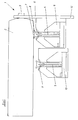
- FIG. 6 is a cross section through a second Embodiment of a roller conveyor according to the invention comparable to the representation shown in Fig. 1.
- the same parts have the same reference numbers characterized.
- Deviating from the representation according to FIG. 1 is here on the upper edge of the circumferential belt 4 or the return belt 5 in the upper end area or arranged at the upper edge a profile element 6 ' in its geometric configuration deviates from that Embodiment according to FIG. 1 is configured.
- the Profile element 6 ' is in the holder 9 or at returning belt in the bracket 10 to drive and Guide elements 11, in particular on the Attack profile element 6 '.
- the drive elements 11 have Roller and / or ball bearings.
- the vertical belt 5 laterally arranged ball bearings 19th provided with which better cornering is achieved becomes.
- Fig. 7 is a cross-sectional view of the belt with the profile element arranged thereon according to FIG. 6 shown.
- the two elongated sections 13 'and 14' connecting between form a notch and are designed so that the belt 4 or the belt 5 can be inserted between them and sewn there or attached in some other way.
- the upper area 15 ' is wider than the lower area formed with the elongated portions 13 'and 14'.
- the upper region 15 ' has an upper curved one End surface 20, the highest in the middle Has point and drops outwards. Overall, the top one Area 15 'designed in the manner of a circular segment.
- the recess 21 which is elongate in cross section, is therefore also arched, the highest point being the Recess, as well as the highest point of the End surface 20 just above the vertical belt 5 is arranged and something on both outer sides is sloping.
Abstract
Description
Die Erfindung betrifft einen Rollenförderer mit drehbar angeordneten Rollen zum Transport von Gütern und mit einem unterhalb der Rollen angeordneten Riemen zum Antrieb der Rollen, wobei der Riemen im wesentlichen vertikal ausgerichtet ist.The invention relates to a roller conveyor with rotatable arranged rollers for the transport of goods and with a Belts arranged below the rollers for driving the Rolling with the belt essentially vertical is aligned.
Derartige Rollenförderer mit angetriebenen Rollenbahnen sind bekannt. Grundsätzlich erfolgen diese Antriebe entweder über Ketten oder über Riemen. Riemen haben gegenüber Ketten die Vorteile, daß ein Antrieb mit Riemen vergleichsweise geräuscharm ist und sich hohe Geschwindigkeiten erzielen lassen. Beim Antrieb mit Riemen wird ein Antrieb mit Flachriemen und Rundriemen unterschieden. Zu den Flachriemen gehören auch Zahnriemen. Demgegenüber fallen Keilriemen unter den Oberbegriff Rundriemen. Der Flachriemen hat den Vorteil, daß große Kräfte übertragen werden können. Jedoch ist der Flachriemen aufgrund seiner horizontalen Ausrichtung unter den Rollen nicht zu den Seiten biegbar und daher nur für den Antrieb in geraden Streckenabschnitten geeignet. In den Flachriemen sind Zugträger, wie beispielsweise Kevlarfäden oder Drahtzüge oder auch nur ganz allgemein ein besonders strapazierfähiges Gewebe integriert, so daß mit dem Flachriemen mit seinem im wesentlichen rechteckigen Profil Rollenförderer mit Längen von etwa 20m bis 30m antreibbar sind. Demgegenüber sind Rundriemen auch zu den Seiten führbar und können daher auch zum Antrieb beispielsweise in Kurven verwendet werden. Derartige Rundriemen sind jedoch in der Regel nur für Rollenförderer bis zu 10m geeignet.Such roller conveyors with driven roller conveyors are known. Basically, these drives are made either over chains or over straps. Have straps compared to chains the advantages that a drive with a belt is comparatively quiet and high Allow speeds to be achieved. When driving with a belt becomes a drive with flat belts and round belts distinguished. Toothed belts also belong to the flat belts. In contrast, V-belts fall under the generic term Round belts. The flat belt has the advantage that large Forces can be transferred. However, that is Flat belt due to its horizontal orientation below the rolls cannot be bent to the sides and therefore only for the drive is suitable in straight sections. In the flat belts are tension members, such as Kevlar threads or wire pulls or just in general a particularly durable fabric integrated, so that with the flat belt with its essentially rectangular profile roller conveyor with lengths of about 20m can be driven up to 30m. In contrast, round belts are also Can be guided to the sides and can therefore also be used for the drive can be used in curves, for example. such However, round belts are usually only for roller conveyors suitable up to 10m.
Der Erfindung liegt die Aufgabe zugrunde, einen Rollenförderer der eingangs genannten Art zu schaffen, der auch in Kurvenbereichen mit einem besonders belastbaren Riemen antreibbar ist.The invention has for its object a To create roller conveyor of the type mentioned, the even in curve areas with a particularly resilient Belt is drivable.
Die Lösung dieser Aufgabe erfolgt mit einem Rollenförderer mit den Merkmalen des Anspruchs 1. Vorteilhafte Weiterbildungen der Erfindung sind in den Unteransprüchen beschrieben.This task is solved with a roller conveyor with the features of claim 1. Advantageous Further developments of the invention are in the subclaims described.
Erfindungswesentlich bei einem Rollenförderer mit drehbar angeordneten Rollen zum Transport von Gütern und mit einem unterhalb der Rollen angeordneten Riemen zum Antrieb der Rollen ist dabei, wobei der Riemen im wesentlichen vertikal ausgerichtet ist, daß an der oberen, mit den Rollen in Kontakt tretenden Kante des Riemens ein durchgängiges Profilelement angeordnet ist und daß das Profilelement breiter als der Riemen ausgebildet ist und diesen zu beiden Seiten überragt. Es kann dabei ein länglich ausgebildeter Riemen, insbesondere mit im wesentlichen rechteckigem Profil verwendet werden, der ausreichend mit Zugträgern, wie Kevlarfäden oder Drähten versehen ist und auf diese Weise besonders hohen Zugkräften standhält und entsprechend lang ausgebildet sein kann. Durch die vertikale Ausrichtung des Riemens ist auch eine seitliche Verbiegung möglich, und der Riemen kann den Kurven und Bögen des Rollenförderers folgen. Bei einer derartigen Ausrichtung ist weiterhin von Vorteil, daß sich auf der relativ schmalen oberen Kante des Profilelementes weniger Schmutz ansammeln kann und damit auch weniger Schmutz auf die Rollen und das zu fördernde Gut übertragen wird. Auch der Wartungsaufwand ist dadurch geringer. Dies insbesondere deshalb, da die obere Breite des Profilelementes kleiner ist als die sonst übliche Breite des Riemens bzw. im vorliegenden Fall die Breite des Profilelementes kleiner ist als die Höhe des vertikal angeordneten Riemens. Das Profilelement ist dabei durchgängig und unterbrechungsfrei über die gesamte Länge des Riemens ausgebildet, so daß ein ständiger Kontakt des Profilelementes mit den durch den Riemen und das Profilelement angetriebenen Rollen gegeben ist. Das Profilelement ist breiter als der Riemen ausgebildet und überragt diesen zu beiden Seiten, so daß eine gute Kraftübertragung gewährleistet ist. Dabei ist das Profilelement bevorzugt symmetrisch, insbesondere symmetrisch zur vertikalen Achse des Riemens ausgebildet.Essential to the invention in a roller conveyor with rotatable arranged rollers for the transport of goods and with a Belts arranged below the rollers for driving the Rolling is included, with the belt essentially is aligned vertically that at the top, with the Roll in contacting edge of the belt continuous profile element is arranged and that Profile element is wider than the belt and towered over on both sides. It can be a elongated strap, especially with in essential rectangular profile can be used, the sufficient with tension members, such as Kevlar threads or wires is provided and in this way particularly high Withstands tensile forces and trained accordingly long can be. Due to the vertical alignment of the belt lateral bending is also possible, and the belt can follow the curves and arches of the roller conveyor. at such an alignment is also advantageous that on the relatively narrow upper edge of the Profile element can accumulate less dirt and thus also less dirt on the rollers and what needs to be conveyed Is transferred well. This also means the maintenance effort lower. This is particularly because the top width of the profile element is smaller than the usual one Width of the belt or in this case the width of the profile element is smaller than the height of the vertical arranged belt. The profile element is included consistent and uninterrupted over the entire length of the belt so that constant contact of the Profile element with the through the belt and that Profile element driven rollers is given. The Profile element is wider and wider than the belt towers above this on both sides, so that a good one Power transmission is guaranteed. It is Profile element preferably symmetrical, in particular symmetrical to the vertical axis of the belt.
Bevorzugt weist das Profilelement Polyurethan auf oder besteht aus Polyurethan oder einem anderen Material, das einen vergleichsweise hohen Reibungskoeffizienten aufweist und zudem seitlich biegbar ist. Das Profilelement ist bevorzugt im wesentlichen "T"-förmig ausgebildet. Das bedeutet, daß das "zentrale Bein" des "T's" mit einem mittleren Schlitz ausgestattet auf den Riemen aufsetzbar und mit diesem verbindbar ist und der obere Querbalken des "T's" mit einem im Vergleich zur Oberkante des Riemens verbreiterten Fläche zur Anlage an der Rolle kommen kann. Besonders bevorzugt ist das Profilelement dabei als 2-Punkt-Auflage ausgebildet. Bei einer Ausbildung als T-Profil sind dabei die beiden äußeren Enden nach oben gewölbt, so daß sich insgesamt eine muldenartige Biegung oder Wölbung ergibt. Die beiden äußeren Bereiche bilden dann die 2-Punkt-Auflage. The profile element preferably has or is made of polyurethane or another material that has a comparatively high coefficient of friction and is also laterally bendable. The profile element is preferably essentially "T" -shaped. The means that the "central leg" of the "T's" with a middle slot fitted onto the strap and can be connected to it and the upper crossbar of "T's" with a compared to the top edge of the belt widened area can come to rest on the roll. The profile element is particularly preferred as a 2-point support educated. When training as a T-profile the two outer ends are facing up arched, so that there is an overall trough-like bend or bulge. Form the two outer areas then the 2-point edition.
In einer anderen besonders bevorzugten Ausgestaltung ist das Profilelement derart gewölbt ausgebildet, daß sich eine hügelartige oder konvexe Wölbung ergibt. Dabei ist der mittlere, mit den Rollen in Kontakt tretende Teil des Profilelementes höher als die Außenbereiche des Profilelementes, die seitlich über den Riemen hinausragen. Das Profilelement ist dabei bevorzugt kreissegmentartig ausgebildet und weist in einer weiteren bevorzugten Ausführungsform eine Ausnehmung auf, wobei die Ausnehmung günstigerweise eine längliche Form hat und in konstantem Abstand zur oberen Abschlußfläche des Profilelementes ausgebildet ist. Durch diese Ausnehmung wird erreicht, daß das Profilelement pufferartig nachgeben kann und eine in Längsrichtung des Riemens erfolgende Umschlingung der Rollen erfolgen kann, so daß das Profilelement nicht nur an einem Punkt mit der Rolle in Kontakt kommt, sondern in Zugrichtung gesehen auf einer gewissen Länge.In another particularly preferred embodiment the profile element is curved such that gives a hill-like or convex curvature. It is the middle part of the Profile element higher than the outer areas of the Profile elements that protrude laterally beyond the belt. The profile element is preferably a segment of a circle trained and points in another preferred Embodiment has a recess, the recess conveniently has an elongated shape and constant Distance to the upper end face of the profile element is trained. This recess ensures that the profile element can yield like a buffer and one in Longitudinal direction of the belt wrapping Rolling can be done so that the profile element not only comes into contact with the role at one point, but in Direction of pull seen over a certain length.
Der Riemen ist im Querschnitt im wesentlichen rechteckig ausgebildet. Derartige Riemen sind besonders einfach und belastbar herstellbar. In einer anderen bevorzugten Weiterentwicklung der Erfindung sind der Riemen und das Profilelement einstückig ausgebildet.The belt is essentially rectangular in cross section educated. Such straps are particularly simple and resilient to manufacture. In another preferred Further development of the invention are the belt and that Profile element formed in one piece.
Der Riemen ist bevorzugt im Bereich der Innenkurve des Rollenförderers angeordnet und liegt in diesem Bereich an den Rollen an. Der Rollenförderer weist günstigerweise ballige Antriebs- und Führungselemente auf, mit denen der vertikal liegende Riemen geführt wird, um ein Verdrehen zu verhindern. Weiterhin ist es günstig, an dem vertikal ausgerichteten Riemen seitlich angeordnete Kugellager vorzusehen. Dadurch wird eine besonders gute Kurvenführung erreicht. Die Kugellager sind bevorzugt in Kurvenbereichen im Außenradius angeordnet. In einer Weiterentwicklung sind die Kugellager mit gewissen Abständen alternierend zu beiden Seiten des Riemens angeordnet.The belt is preferably in the area of the inner curve of the Roller conveyor arranged and is in this area the roles. The roller conveyor conveniently points crowned drive and guide elements with which the vertically lying belt is guided to prevent twisting prevent. Furthermore, it is cheap on the vertical aligned belt laterally arranged ball bearings provided. This ensures particularly good cornering reached. The ball bearings are preferred in curve areas arranged in the outer radius. Are in a further development the ball bearings alternate at certain intervals arranged on both sides of the belt.
Ein weiterer Aspekt der Erfindung besteht in der Bereitstellung eines Riemens für den erfindungsgemäßen Rollenförderer mit den oben beschriebenen bevorzugten Ausgestaltungen.Another aspect of the invention is in Provision of a belt for the invention Roller conveyors with the preferred described above Configurations.
Nachfolgend wird die Erfindung anhand eines in der Zeichnung dargestellten bevorzugten Ausführungsbeispiels weiter erläutert. Im einzelnen zeigen die schematischen Darstellungen in:
- Fig. 1:
- eine Querschnittsansicht eines erfindungsgemäßen Rollenförderers;
- Fig. 2:
- eine perspektivische Ansicht eines Ausschnitts eines erfindungsgemäßen Rollenförderers;
- Fig. 3:
- eine Querschnittsansicht eines Profilelementes;
- Fig. 4:
- eine schematische Ansicht einer ersten Ausbildung eines erfindungsgemäßen Rollenförderers;
- Fig. 5:
- eine schematische Ansicht einer zweiten Ausbildung eines erfindungsgemäßen Rollenförderers;
- Fig. 6:
- eine Querschnittsansicht einer zweiten
Ausführungsform eines erfindungsgemäßen
Rollenförders;
und - Fig. 7:
- eine Querschnittsansicht des Riemens mit einem Profilelement gemäß der Ausführungsform gemäß Fig. 6.
- Fig. 1:
- a cross-sectional view of a roller conveyor according to the invention;
- Fig. 2:
- a perspective view of a section of a roller conveyor according to the invention;
- Fig. 3:
- a cross-sectional view of a profile element;
- Fig. 4:
- a schematic view of a first embodiment of a roller conveyor according to the invention;
- Fig. 5:
- a schematic view of a second embodiment of a roller conveyor according to the invention;
- Fig. 6:
- a cross-sectional view of a second embodiment of a roller conveyor according to the invention;
and - Fig. 7:
- 6 shows a cross-sectional view of the belt with a profile element according to the embodiment according to FIG. 6.
In Fig. 1 ist ein Querschnitt durch einen erfindungsgemäßen
Rollenförderer dargestellt. Eine Rolle 2 mit einer
Achse 3 ist in einer Seitenwange 12 gehalten. Eine
Vielzahl von solchen hintereinander angeordneten Rollen 2
bilden den wesentlichen Teil des generell mit 1
bezeichneten Rollenförderers. Der Rollenförderer wird von
einem vertikal angeordneten Riemen 4 mit im wesentlichen
länglichem bzw. rechteckigem Querschnitt angetrieben.
Derselbe umlaufende Riemen ist in seinem rücklaufenden
Abschnitt mit 5 bezeichnet. Dieser rücklaufende Abschnitt
des Riemens 5 ist tiefer geführt als der hinlaufende
antreibende Abschnitt des Riemens 4, so daß nur der obere
Bereich des Riemens 4 zur Anlage an die Rollen 2 kommt.
Hierzu ist der Riemen 4 in einer Halterung 9 bzw. der
rücklaufende Riemen 5 in einer Halterung 10 gehalten bzw.
mit Antriebselementen 11 geführt und angetrieben. Der
Riemen 4 weist an seiner oberen Kante ein Profilelement 6
auf, das zwei vorgewölbte bzw. nach oben gewölbte Bereiche
7 und 8 aufweist, die eine 2-Punkt-Auflage an der Rolle 2
bilden.In Fig. 1 is a cross section through an inventive
Roller conveyor shown. A
In Fig. 2 ist eine perspektivische Ansicht des
Rollenförderers 1 gemäß Fig. 1 dargestellt. Gleiche Teile
sind mit gleichen Bezugszahlen gekennzeichnet. Deutlicher
zu erkennen sind hier die in den Halterungen 9 und 10
angeordneten Antriebselemente bzw. Führungselemente 11.2 is a perspective view of the
Roller conveyor 1 shown in FIG. 1. Same parts
are identified by the same reference numbers. More clear
can be seen here in the
In Fig. 3 ist eine Querschnittsansicht eines Profilelementes
6 dargestellt. Dieses ist im wesentlichen T-förmig
ausgebildet, wobei das zentrale Bein des T's von
den beiden länglichen Abschnitten 13 und 14 gebildet ist,
die zwischen sich eine Kerbe einschließen und insgesamt so
ausgebildet sind, daß zwischen ihnen der Riemen 4 bzw. 5
einschiebbar und dort festnähbar oder auf andere Weise zu
befestigen ist. Der obere Bereich 15 ist verbreitert
ausgebildet, so daß insgesamt eine gegenüber der Oberkante
des Riemens verbreiterte Auflagefläche entsteht. Dabei
sind die beiden äußeren Endbereiche 7 und 8 hoch gewölbt,
so daß eine 2-Punkt-Auflage gebildet ist. In den
seitlichen Bereichen sind kreisförmige, nach außen
gewölbte und verdickte Bereiche 16 ausgebildet, an denen
Antriebs- und Führungselemente angreifen können. Durch die
verstärkt und kugelförmig nach außen ausgebildeten
Bereiche 16 wird verschleißbedingtem Ausfall des
Rollenförderers entgegengewirkt.3 is a cross-sectional view of a
In Fig. 4 ist eine erste Ausbildung eines erfindungsgemäßen
Rollenförderers dargestellt. Der antreibende
Riemen 4 läuft in Pfeilrichtung. Durch die erfindungsgemäße
Verwendung der Riemen ist es möglich, diesen auch
in einem Ein- oder Ausschleuser zu verwenden, ohne daß
hierfür weitere Motoren notwendig wären, so wie in Fig. 4
dargestellt.4 is a first embodiment of an inventive
Roller conveyor shown. The driving
In Fig. 5 ist eine S-Kurve dargestellt, bei der der
antreibende Riemen 4 immer an der Innenseite der Kurve
geführt ist, wobei dann im zentralen Abschnitt der Kurve,
an dem sich mathematisch gesprochen das Vorzeichen der
Steigung ändert, die Riemen auf die andere Seite geführt
werden, so daß dann der antreibende Riemen 4 wieder auf
der Innenbahn der Kurve des Rollenförderers entlang läuft.5 shows an S curve, in which the
driving
In Fig. 6 ist ein Querschnitt durch eine zweite
Ausführungsform eines erfindungsgemäßen Rollenförderers
vergleichbar zur Darstellung in Fig. 1 dargestellt.
Gleiche Teile sind mit gleichen Bezugszahlen
gekennzeichnet. Abweichend zur Darstellung gemäß Fig. 1
ist hier an der oberen Kante des umlaufenden Riemens 4
bzw. des rücklaufenden Riemens 5 im oberen Endbereich bzw.
an der oberen Kante ein Profilelement 6' angeordnet, das
in seiner geometrischen Ausgestaltung abweichend von der
Ausführungsform gemäß Fig. 1 ausgestaltet ist. Das
Profilelement 6' liegt in der Halterung 9 bzw. beim
rücklaufenden Riemen in der Halterung 10 an Antriebs- und
Führungselementen 11 an, die insbesondere an dem
Profilelement 6' angreifen. Die Antriebselemente 11 weisen
Rollen- und/oder Kugellager auf. Weiterhin sind hier an
dem vertikalen Riemen 5 seitlich angeordnete Kugellager 19
vorgesehen, mit denen eine bessere Kurvenführung erreicht
wird.6 is a cross section through a second
Embodiment of a roller conveyor according to the invention
comparable to the representation shown in Fig. 1.
The same parts have the same reference numbers
characterized. Deviating from the representation according to FIG. 1
is here on the upper edge of the
In Fig. 7 ist eine Querschnittsansicht des Riemens mit dem
darauf angeordneten Profilelement gemäß Fig. 6
dargestellt. Auf dem vertikalen Riemen 5 ist das
Profilelement 6' angeordnet, das einen oberen verbreiterten
Bereich 15' aufweist, der sich an die beiden
länglichen Abschnitte 13' und 14' anschließt, die zwischen
sich eine Kerbe bilden und so ausgebildet sind, daß
zwischen ihnen der Riemen 4 bzw. der Riemen 5 einschiebbar
und dort festgenäht oder auf andere Weise befestigt ist.
Der obere Bereich 15' ist breiter als der untere Bereich
mit den länglichen Abschnitten 13' und 14' ausgebildet.
Der obere Bereich 15' weist eine obere gewölbte
Abschlußfläche 20 auf, die in der Mitte ihren höchsten
Punkt hat und nach außen abfällt. Insgesamt ist der obere
Bereich 15' nach Art eines Kreissegmentes ausgebildet. In
dem oberen Bereich 15' ist zudem eine durch das
Profilelement 6' verlaufende Ausnehmung 21 vorgesehen, die
mit konstantem Abstand zur Abschlußfläche 20 ausgebildet
ist. Die im Querschnitt längliche Ausnehmung 21 ist daher
ebenfalls gewölbt ausgebildet, wobei der höchste Punkt der
Ausnehmung, so wie auch der höchste Punkt der
Abschlußfläche 20 genau oberhalb des vertikalen Riemens 5
angeordnet ist und zu beiden äußeren Seiten etwas
abfallend ausgebildet ist. Durch diese Ausbildung wird
erreicht, daß insbesondere durch die Ausnehmung 21 oder
den Hohlraum eine Pufferfunktion gegeben ist und senkrecht
zur Bildebene eine Umschlingung der angetriebenen Rolle
erfolgen kann, so daß sich der Bereich, in dem das
Profilelement 6' an der Rolle 2 anliegt, vergrößert.In Fig. 7 is a cross-sectional view of the belt with the
profile element arranged thereon according to FIG. 6
shown. On the
Claims (15)
dadurch gekennzeichnet, daß an der oberen, mit den Rollen (2) in Kontakt tretenden Kante des Riemens (4, 5) ein durchgängiges Profilelement (6) angeordnet ist, und
daß das Profilelement (6, 6') breiter als der Riemen (4, 5) ausgebildet ist und diesen zu beiden Seiten überragt.Roller conveyor with rotatably arranged rollers (2) for transporting goods with a belt (4, 5) arranged below the rollers (2) for driving the rollers (2), the belt (4, 5) being oriented substantially vertically,
characterized in that a continuous profile element (6) is arranged on the upper edge of the belt (4, 5) which comes into contact with the rollers (2), and
that the profile element (6, 6 ') is wider than the belt (4, 5) and projects beyond it on both sides.
Applications Claiming Priority (2)
| Application Number | Priority Date | Filing Date | Title |
|---|---|---|---|
| DE20207498U | 2002-05-14 | ||
| DE20207498U DE20207498U1 (en) | 2002-05-14 | 2002-05-14 | roller conveyors |
Publications (3)
| Publication Number | Publication Date |
|---|---|
| EP1362803A2 true EP1362803A2 (en) | 2003-11-19 |
| EP1362803A3 EP1362803A3 (en) | 2007-05-09 |
| EP1362803B1 EP1362803B1 (en) | 2009-03-25 |
Family
ID=28685423
Family Applications (1)
| Application Number | Title | Priority Date | Filing Date |
|---|---|---|---|
| EP03010371A Expired - Lifetime EP1362803B1 (en) | 2002-05-14 | 2003-05-08 | Roller conveyor |
Country Status (10)
| Country | Link |
|---|---|
| US (1) | US6805234B2 (en) |
| EP (1) | EP1362803B1 (en) |
| JP (1) | JP3954524B2 (en) |
| CN (1) | CN1280165C (en) |
| AT (1) | ATE426569T1 (en) |
| AU (1) | AU2003204126C1 (en) |
| DE (2) | DE20207498U1 (en) |
| DK (1) | DK1362803T3 (en) |
| ES (1) | ES2322647T3 (en) |
| PT (1) | PT1362803E (en) |
Families Citing this family (15)
| Publication number | Priority date | Publication date | Assignee | Title |
|---|---|---|---|---|
| DE202004019961U1 (en) * | 2004-12-21 | 2006-05-04 | Transnorm System Gmbh | Belt for use in conveyor systems has edge strip with leg extending over part of belt and sewn to it, and leg on outer side has slot in which is located seam for connecting of edge strip to belt |
| DE202004019963U1 (en) * | 2004-12-21 | 2006-04-27 | Transnorm System Gmbh | Mechanical handling system roller conveyer has roller over two upright drives either side of a vertical drive belt |
| US20060260913A1 (en) * | 2005-05-20 | 2006-11-23 | Wolf Stephen C | Retractable multiple-stage trailer loader/unloader apparatus |
| US7364035B2 (en) * | 2005-05-25 | 2008-04-29 | Dematic Corp. | Airless accumulation conveyor |
| JP5006550B2 (en) * | 2006-02-13 | 2012-08-22 | シブヤ精機株式会社 | Roller conveyor |
| US7240612B1 (en) * | 2006-05-03 | 2007-07-10 | Illinois Tool Works Inc. | Strapping machine |
| JP4957307B2 (en) * | 2007-03-19 | 2012-06-20 | 株式会社ダイフク | Conveyor equipment |
| JP4910874B2 (en) * | 2007-05-16 | 2012-04-04 | 株式会社ダイフク | Conveyor equipment |
| JP5082658B2 (en) * | 2007-08-03 | 2012-11-28 | 株式会社ダイフク | Conveyor equipment |
| JP5082659B2 (en) * | 2007-08-03 | 2012-11-28 | 株式会社ダイフク | Conveyor equipment |
| JP2012076929A (en) * | 2011-12-15 | 2012-04-19 | Shibuya Seiki Co Ltd | Roller conveyor |
| US20140224622A1 (en) * | 2013-02-08 | 2014-08-14 | Dematic Corp. | Low rate singulator |
| US10040633B2 (en) | 2015-11-04 | 2018-08-07 | Intelligrated Headquarters, Llc | Belt-driven roller conveyor |
| EP3494074A1 (en) * | 2016-08-05 | 2019-06-12 | Intelligrated Headquarters, LLC | Belt-driven roller conveyor |
| WO2020136799A1 (en) * | 2018-12-27 | 2020-07-02 | 株式会社協和製作所 | Finger guard member and finger guard member coupling structure |
Citations (5)
| Publication number | Priority date | Publication date | Assignee | Title |
|---|---|---|---|---|
| FR2108878A1 (en) * | 1970-10-12 | 1972-05-26 | Gallet & Cie | |
| US3901379A (en) * | 1970-11-12 | 1975-08-26 | Marryat Finance Ltd | Angular guidance for conveyor belt systems |
| DE3308263A1 (en) * | 1983-03-09 | 1984-09-20 | Mannesmann AG, 4000 Düsseldorf | Roller conveyor path |
| US4588073A (en) * | 1984-09-26 | 1986-05-13 | Alvey Inc. | Padded chain live roller conveyor |
| US5007526A (en) * | 1989-10-05 | 1991-04-16 | Ermanco Incorporated | Conveyor curve and live roller, line shaft conveyor system incorporating same |
Family Cites Families (11)
| Publication number | Priority date | Publication date | Assignee | Title |
|---|---|---|---|---|
| CH512381A (en) * | 1969-08-05 | 1971-09-15 | Stoehr Foerderanlagen Salzer | Roller conveyor |
| DE1951476A1 (en) * | 1969-10-13 | 1971-07-08 | Meyer Geb Urbank | Lying mat |
| FR2069967B1 (en) * | 1969-12-17 | 1974-05-03 | Lemaresquier Pierre | |
| DE2213291A1 (en) * | 1972-03-18 | 1973-09-27 | Richard Gebhardt | DRIVE DEVICE FOR ROLLER TRACKS |
| US4473148A (en) * | 1982-09-17 | 1984-09-25 | Lear Siegler, Inc. | Motion sensor for motion sensing accumulator |
| US4753339A (en) * | 1987-05-20 | 1988-06-28 | The Buschman Company | Accumulating conveyor of the low pressure type |
| MX9203847A (en) * | 1991-07-03 | 1993-12-01 | Litton Automation Systems | ZERO PRESSURE ACCUMULATION CONVEYOR. |
| US5176246A (en) * | 1992-03-02 | 1993-01-05 | Alvey, Inc. | Padded chain drive for roller conveyors |
| DE9218640U1 (en) * | 1992-03-26 | 1994-11-17 | Axmann Foerdertechnik | Roller conveyor curve |
| US5984082A (en) * | 1997-09-12 | 1999-11-16 | Fenner, Inc. | Roller-bed conveyor drive assembly |
| US6390286B1 (en) * | 1999-01-08 | 2002-05-21 | Rapistan Systems Advertising Corp. | Belt driven roller conveyor |
-
2002
- 2002-05-14 DE DE20207498U patent/DE20207498U1/en not_active Expired - Lifetime
-
2003
- 2003-05-08 DE DE50311324T patent/DE50311324D1/en not_active Expired - Lifetime
- 2003-05-08 ES ES03010371T patent/ES2322647T3/en not_active Expired - Lifetime
- 2003-05-08 AT AT03010371T patent/ATE426569T1/en active
- 2003-05-08 PT PT03010371T patent/PT1362803E/en unknown
- 2003-05-08 EP EP03010371A patent/EP1362803B1/en not_active Expired - Lifetime
- 2003-05-08 DK DK03010371T patent/DK1362803T3/en active
- 2003-05-09 AU AU2003204126A patent/AU2003204126C1/en not_active Ceased
- 2003-05-12 US US10/436,314 patent/US6805234B2/en not_active Expired - Lifetime
- 2003-05-13 JP JP2003133963A patent/JP3954524B2/en not_active Expired - Fee Related
- 2003-05-14 CN CNB031312837A patent/CN1280165C/en not_active Expired - Fee Related
Patent Citations (5)
| Publication number | Priority date | Publication date | Assignee | Title |
|---|---|---|---|---|
| FR2108878A1 (en) * | 1970-10-12 | 1972-05-26 | Gallet & Cie | |
| US3901379A (en) * | 1970-11-12 | 1975-08-26 | Marryat Finance Ltd | Angular guidance for conveyor belt systems |
| DE3308263A1 (en) * | 1983-03-09 | 1984-09-20 | Mannesmann AG, 4000 Düsseldorf | Roller conveyor path |
| US4588073A (en) * | 1984-09-26 | 1986-05-13 | Alvey Inc. | Padded chain live roller conveyor |
| US5007526A (en) * | 1989-10-05 | 1991-04-16 | Ermanco Incorporated | Conveyor curve and live roller, line shaft conveyor system incorporating same |
Also Published As
| Publication number | Publication date |
|---|---|
| AU2003204126B2 (en) | 2005-05-05 |
| PT1362803E (en) | 2009-06-17 |
| DE20207498U1 (en) | 2003-09-25 |
| ATE426569T1 (en) | 2009-04-15 |
| ES2322647T3 (en) | 2009-06-24 |
| JP3954524B2 (en) | 2007-08-08 |
| JP2004043181A (en) | 2004-02-12 |
| DK1362803T3 (en) | 2009-06-15 |
| US20030213679A1 (en) | 2003-11-20 |
| EP1362803B1 (en) | 2009-03-25 |
| CN1462715A (en) | 2003-12-24 |
| US6805234B2 (en) | 2004-10-19 |
| CN1280165C (en) | 2006-10-18 |
| AU2003204126A1 (en) | 2003-12-04 |
| EP1362803A3 (en) | 2007-05-09 |
| AU2003204126C1 (en) | 2005-11-10 |
| DE50311324D1 (en) | 2009-05-07 |
Similar Documents
| Publication | Publication Date | Title |
|---|---|---|
| DE102007032341B4 (en) | Conveyor belt of a chain conveyor with innovative driver links | |
| EP1362803A2 (en) | Roller conveyor | |
| DE2431668C3 (en) | Transport conveyor chain with variable step length of the multi-part links | |
| DE102011050425B4 (en) | Round steel chain | |
| DE3615734C2 (en) | ||
| DE19616907C5 (en) | Conveyor track for general cargo, especially for luggage containers | |
| DE602005001846T2 (en) | BAND WITH OPENINGS USED FOR SUPPORTING AND GUIDING CLOTHING IN HANGING SUPPORT SYSTEMS | |
| DE3521720A1 (en) | DEVICE FOR CONVEYING AND SORTING ITEMS | |
| DE3612765A1 (en) | Rolling belt | |
| DE102011050936A1 (en) | Conveyor belt system and conveyor belt | |
| EP2210831A1 (en) | Conveyor device and transport body | |
| CH703149B1 (en) | Roller drive element. | |
| EP1412265B1 (en) | Accumulation-capable curved element for a transfer system | |
| DE2417516B2 (en) | DEVICE FOR A CHAIN WITH HOLDER ARRANGEMENTS FOR CARRYING AND GUIDING ONE OR MORE BENDABLE ENERGY-TRANSMITTING CABLES | |
| WO2006094423A1 (en) | Transport device, rolling body and transport body | |
| DE4124788A1 (en) | Arrow tooth chain for tunnel construction - has steel links with horizontal and vertical faces for smoother running of chain wheel | |
| EP1832531B1 (en) | Powered roller conveyor curve and conveyor belt with such a roller conveyor curve | |
| WO2019068552A1 (en) | Passenger conveying device with step chain guided by track rollers and buffer rollers, and method for guiding a step chain using track rollers and buffer rollers | |
| CH663773A5 (en) | CONTINUOUS. | |
| EP1103736A1 (en) | Chain cage for rolling members | |
| AT394489B (en) | CURTAIN DEVICE | |
| WO2000063096A1 (en) | Continuous transporter | |
| DE163023C (en) | ||
| DE19957110A1 (en) | Roll body chain with rolls in sequence, measurement of which along guide belt in side wall sectors of which is smaller than radius of roll bodies | |
| DE102015214746A1 (en) | Horizontal conveyor section with curve-guided mat chain for transporting articles or piece goods |
Legal Events
| Date | Code | Title | Description |
|---|---|---|---|
| PUAI | Public reference made under article 153(3) epc to a published international application that has entered the european phase |
Free format text: ORIGINAL CODE: 0009012 |
|
| AK | Designated contracting states |
Kind code of ref document: A2 Designated state(s): AT BE BG CH CY CZ DE DK EE ES FI FR GB GR HU IE IT LI LU MC NL PT RO SE SI SK TR |
|
| AX | Request for extension of the european patent |
Extension state: AL LT LV MK |
|
| PUAL | Search report despatched |
Free format text: ORIGINAL CODE: 0009013 |
|
| AK | Designated contracting states |
Kind code of ref document: A3 Designated state(s): AT BE BG CH CY CZ DE DK EE ES FI FR GB GR HU IE IT LI LU MC NL PT RO SE SI SK TR |
|
| AX | Request for extension of the european patent |
Extension state: AL LT LV MK |
|
| 17P | Request for examination filed |
Effective date: 20070709 |
|
| AKX | Designation fees paid |
Designated state(s): AT BE BG CH CY CZ DE DK EE ES FI FR GB GR HU IE IT LI LU MC NL PT RO SE SI SK TR |
|
| 17Q | First examination report despatched |
Effective date: 20080421 |
|
| GRAP | Despatch of communication of intention to grant a patent |
Free format text: ORIGINAL CODE: EPIDOSNIGR1 |
|
| GRAS | Grant fee paid |
Free format text: ORIGINAL CODE: EPIDOSNIGR3 |
|
| GRAA | (expected) grant |
Free format text: ORIGINAL CODE: 0009210 |
|
| AK | Designated contracting states |
Kind code of ref document: B1 Designated state(s): AT BE BG CH CY CZ DE DK EE ES FI FR GB GR HU IE IT LI LU MC NL PT RO SE SI SK TR |
|
| REG | Reference to a national code |
Ref country code: GB Ref legal event code: FG4D Free format text: NOT ENGLISH |
|
| REG | Reference to a national code |
Ref country code: CH Ref legal event code: EP |
|
| REG | Reference to a national code |
Ref country code: IE Ref legal event code: FG4D Free format text: LANGUAGE OF EP DOCUMENT: GERMAN |
|
| REF | Corresponds to: |
Ref document number: 50311324 Country of ref document: DE Date of ref document: 20090507 Kind code of ref document: P |
|
| REG | Reference to a national code |
Ref country code: DK Ref legal event code: T3 |
|
| REG | Reference to a national code |
Ref country code: PT Ref legal event code: SC4A Free format text: AVAILABILITY OF NATIONAL TRANSLATION Effective date: 20090608 |
|
| REG | Reference to a national code |
Ref country code: ES Ref legal event code: FG2A Ref document number: 2322647 Country of ref document: ES Kind code of ref document: T3 |
|
| PG25 | Lapsed in a contracting state [announced via postgrant information from national office to epo] |
Ref country code: SI Free format text: LAPSE BECAUSE OF FAILURE TO SUBMIT A TRANSLATION OF THE DESCRIPTION OR TO PAY THE FEE WITHIN THE PRESCRIBED TIME-LIMIT Effective date: 20090325 Ref country code: FI Free format text: LAPSE BECAUSE OF FAILURE TO SUBMIT A TRANSLATION OF THE DESCRIPTION OR TO PAY THE FEE WITHIN THE PRESCRIBED TIME-LIMIT Effective date: 20090325 |
|
| PG25 | Lapsed in a contracting state [announced via postgrant information from national office to epo] |
Ref country code: SE Free format text: LAPSE BECAUSE OF FAILURE TO SUBMIT A TRANSLATION OF THE DESCRIPTION OR TO PAY THE FEE WITHIN THE PRESCRIBED TIME-LIMIT Effective date: 20090625 |
|
| REG | Reference to a national code |
Ref country code: IE Ref legal event code: FD4D |
|
| PG25 | Lapsed in a contracting state [announced via postgrant information from national office to epo] |
Ref country code: EE Free format text: LAPSE BECAUSE OF FAILURE TO SUBMIT A TRANSLATION OF THE DESCRIPTION OR TO PAY THE FEE WITHIN THE PRESCRIBED TIME-LIMIT Effective date: 20090325 Ref country code: CZ Free format text: LAPSE BECAUSE OF FAILURE TO SUBMIT A TRANSLATION OF THE DESCRIPTION OR TO PAY THE FEE WITHIN THE PRESCRIBED TIME-LIMIT Effective date: 20090325 |
|
| BERE | Be: lapsed |
Owner name: TRANSNORM SYSTEM G.M.B.H. Effective date: 20090531 |
|
| PG25 | Lapsed in a contracting state [announced via postgrant information from national office to epo] |
Ref country code: SK Free format text: LAPSE BECAUSE OF FAILURE TO SUBMIT A TRANSLATION OF THE DESCRIPTION OR TO PAY THE FEE WITHIN THE PRESCRIBED TIME-LIMIT Effective date: 20090325 Ref country code: RO Free format text: LAPSE BECAUSE OF FAILURE TO SUBMIT A TRANSLATION OF THE DESCRIPTION OR TO PAY THE FEE WITHIN THE PRESCRIBED TIME-LIMIT Effective date: 20090325 |
|
| PG25 | Lapsed in a contracting state [announced via postgrant information from national office to epo] |
Ref country code: MC Free format text: LAPSE BECAUSE OF NON-PAYMENT OF DUE FEES Effective date: 20090531 |
|
| REG | Reference to a national code |
Ref country code: CH Ref legal event code: PL |
|
| PG25 | Lapsed in a contracting state [announced via postgrant information from national office to epo] |
Ref country code: IE Free format text: LAPSE BECAUSE OF FAILURE TO SUBMIT A TRANSLATION OF THE DESCRIPTION OR TO PAY THE FEE WITHIN THE PRESCRIBED TIME-LIMIT Effective date: 20090325 Ref country code: BG Free format text: LAPSE BECAUSE OF FAILURE TO SUBMIT A TRANSLATION OF THE DESCRIPTION OR TO PAY THE FEE WITHIN THE PRESCRIBED TIME-LIMIT Effective date: 20090625 Ref country code: LI Free format text: LAPSE BECAUSE OF NON-PAYMENT OF DUE FEES Effective date: 20090531 Ref country code: CH Free format text: LAPSE BECAUSE OF NON-PAYMENT OF DUE FEES Effective date: 20090531 |
|
| PLBE | No opposition filed within time limit |
Free format text: ORIGINAL CODE: 0009261 |
|
| STAA | Information on the status of an ep patent application or granted ep patent |
Free format text: STATUS: NO OPPOSITION FILED WITHIN TIME LIMIT |
|
| 26N | No opposition filed |
Effective date: 20091229 |
|
| PG25 | Lapsed in a contracting state [announced via postgrant information from national office to epo] |
Ref country code: BE Free format text: LAPSE BECAUSE OF NON-PAYMENT OF DUE FEES Effective date: 20090531 |
|
| PG25 | Lapsed in a contracting state [announced via postgrant information from national office to epo] |
Ref country code: GR Free format text: LAPSE BECAUSE OF FAILURE TO SUBMIT A TRANSLATION OF THE DESCRIPTION OR TO PAY THE FEE WITHIN THE PRESCRIBED TIME-LIMIT Effective date: 20090626 |
|
| PG25 | Lapsed in a contracting state [announced via postgrant information from national office to epo] |
Ref country code: LU Free format text: LAPSE BECAUSE OF NON-PAYMENT OF DUE FEES Effective date: 20090508 |
|
| PG25 | Lapsed in a contracting state [announced via postgrant information from national office to epo] |
Ref country code: HU Free format text: LAPSE BECAUSE OF FAILURE TO SUBMIT A TRANSLATION OF THE DESCRIPTION OR TO PAY THE FEE WITHIN THE PRESCRIBED TIME-LIMIT Effective date: 20090926 |
|
| PG25 | Lapsed in a contracting state [announced via postgrant information from national office to epo] |
Ref country code: TR Free format text: LAPSE BECAUSE OF FAILURE TO SUBMIT A TRANSLATION OF THE DESCRIPTION OR TO PAY THE FEE WITHIN THE PRESCRIBED TIME-LIMIT Effective date: 20090325 |
|
| PG25 | Lapsed in a contracting state [announced via postgrant information from national office to epo] |
Ref country code: CY Free format text: LAPSE BECAUSE OF FAILURE TO SUBMIT A TRANSLATION OF THE DESCRIPTION OR TO PAY THE FEE WITHIN THE PRESCRIBED TIME-LIMIT Effective date: 20090325 |
|
| PGFP | Annual fee paid to national office [announced via postgrant information from national office to epo] |
Ref country code: DK Payment date: 20120516 Year of fee payment: 10 Ref country code: DE Payment date: 20120321 Year of fee payment: 10 Ref country code: NL Payment date: 20120523 Year of fee payment: 10 |
|
| PGFP | Annual fee paid to national office [announced via postgrant information from national office to epo] |
Ref country code: FR Payment date: 20120608 Year of fee payment: 10 Ref country code: GB Payment date: 20120522 Year of fee payment: 10 |
|
| PGFP | Annual fee paid to national office [announced via postgrant information from national office to epo] |
Ref country code: IT Payment date: 20120523 Year of fee payment: 10 |
|
| PGFP | Annual fee paid to national office [announced via postgrant information from national office to epo] |
Ref country code: ES Payment date: 20120525 Year of fee payment: 10 |
|
| PGFP | Annual fee paid to national office [announced via postgrant information from national office to epo] |
Ref country code: PT Payment date: 20120430 Year of fee payment: 10 |
|
| PGFP | Annual fee paid to national office [announced via postgrant information from national office to epo] |
Ref country code: AT Payment date: 20120521 Year of fee payment: 10 |
|
| REG | Reference to a national code |
Ref country code: PT Ref legal event code: MM4A Free format text: LAPSE DUE TO NON-PAYMENT OF FEES Effective date: 20131108 |
|
| REG | Reference to a national code |
Ref country code: NL Ref legal event code: V1 Effective date: 20131201 |
|
| REG | Reference to a national code |
Ref country code: AT Ref legal event code: MM01 Ref document number: 426569 Country of ref document: AT Kind code of ref document: T Effective date: 20130531 |
|
| GBPC | Gb: european patent ceased through non-payment of renewal fee |
Effective date: 20130508 |
|
| PG25 | Lapsed in a contracting state [announced via postgrant information from national office to epo] |
Ref country code: DE Free format text: LAPSE BECAUSE OF NON-PAYMENT OF DUE FEES Effective date: 20131203 Ref country code: AT Free format text: LAPSE BECAUSE OF NON-PAYMENT OF DUE FEES Effective date: 20130531 Ref country code: PT Free format text: LAPSE BECAUSE OF NON-PAYMENT OF DUE FEES Effective date: 20131108 |
|
| REG | Reference to a national code |
Ref country code: DK Ref legal event code: EBP Effective date: 20130531 |
|
| REG | Reference to a national code |
Ref country code: DE Ref legal event code: R119 Ref document number: 50311324 Country of ref document: DE Effective date: 20131203 |
|
| PG25 | Lapsed in a contracting state [announced via postgrant information from national office to epo] |
Ref country code: IT Free format text: LAPSE BECAUSE OF NON-PAYMENT OF DUE FEES Effective date: 20130508 Ref country code: NL Free format text: LAPSE BECAUSE OF NON-PAYMENT OF DUE FEES Effective date: 20131201 |
|
| REG | Reference to a national code |
Ref country code: FR Ref legal event code: ST Effective date: 20140131 |
|
| PG25 | Lapsed in a contracting state [announced via postgrant information from national office to epo] |
Ref country code: GB Free format text: LAPSE BECAUSE OF NON-PAYMENT OF DUE FEES Effective date: 20130508 Ref country code: DK Free format text: LAPSE BECAUSE OF NON-PAYMENT OF DUE FEES Effective date: 20130531 |
|
| PG25 | Lapsed in a contracting state [announced via postgrant information from national office to epo] |
Ref country code: FR Free format text: LAPSE BECAUSE OF NON-PAYMENT OF DUE FEES Effective date: 20130531 |
|
| REG | Reference to a national code |
Ref country code: ES Ref legal event code: FD2A Effective date: 20140606 |
|
| PG25 | Lapsed in a contracting state [announced via postgrant information from national office to epo] |
Ref country code: ES Free format text: LAPSE BECAUSE OF NON-PAYMENT OF DUE FEES Effective date: 20130509 |