EP1362644A1 - Anordnung zum in-line Wiegen von Postgut und Waage - Google Patents
Anordnung zum in-line Wiegen von Postgut und Waage Download PDFInfo
- Publication number
- EP1362644A1 EP1362644A1 EP03009856A EP03009856A EP1362644A1 EP 1362644 A1 EP1362644 A1 EP 1362644A1 EP 03009856 A EP03009856 A EP 03009856A EP 03009856 A EP03009856 A EP 03009856A EP 1362644 A1 EP1362644 A1 EP 1362644A1
- Authority
- EP
- European Patent Office
- Prior art keywords
- scale
- mail piece
- transport
- load cell
- Prior art date
- Legal status (The legal status is an assumption and is not a legal conclusion. Google has not performed a legal analysis and makes no representation as to the accuracy of the status listed.)
- Withdrawn
Links
Images


Classifications
-
- G—PHYSICS
- G01—MEASURING; TESTING
- G01G—WEIGHING
- G01G19/00—Weighing apparatus or methods adapted for special purposes not provided for in the preceding groups
- G01G19/002—Weighing apparatus or methods adapted for special purposes not provided for in the preceding groups for postal parcels and letters
- G01G19/005—Weighing apparatus or methods adapted for special purposes not provided for in the preceding groups for postal parcels and letters with electric or electronic computing means
-
- G—PHYSICS
- G07—CHECKING-DEVICES
- G07B—TICKET-ISSUING APPARATUS; FARE-REGISTERING APPARATUS; FRANKING APPARATUS
- G07B17/00—Franking apparatus
- G07B17/00459—Details relating to mailpieces in a franking system
- G07B17/00661—Sensing or measuring mailpieces
- G07B2017/00701—Measuring the weight of mailpieces
Definitions
- the present invention relates to mail processing, and in particular to a mail weighing system and scale for mail processing machines. Specifically, the present invention relates to a high speed, in-line mail weighing system and scale for mail processing machines, such as sorting machines, inserters, etc.
- the present invention comprises an in-line mail weighing system and scale that is capable of weighing large numbers of mail pieces in succession in a fast and accurate manner.
- the mail weighing scale of the present invention comprises in general a mail piece transport mounted on top of a load cell. As each mail piece is moved through the transport, a series of weight measurements of the transport with mail piece therein are taken by the load cell. A processor then computes the weight measurement of the mail piece based on the series of measurements.
- the mail piece transport of the present invention comprises a scale plate, a drive belt assembly and a pressure assembly.
- the drive belt assembly and the pressure assembly are mounted opposite each other on the scale plate to define a mail piece transport path there between.
- a mail piece enters the mail piece transport, standing on edge, and is propelled there through by the drive belt assembly.
- the pressure assembly applies slight pressure to the mail piece in order to hold the mail piece on edge and against the drive belt assembly.
- Mail pieces move through the mail piece transport one after another, at a constant speed.
- the present invention weighs each mail piece as it is moved through the transport. There is no need to stop or slow down the mail piece on the scale.
- Figures 1 and 2 illustrate a front perspective view and a back perspective view, respectively, of the present invention 10 comprising in general a load cell 20 on which a mail piece transport 30 is mounted.
- the mail piece transport 30 comprises a drive belt assembly 40 and a pressure assembly 70, illustrated as a roller assembly in Figures 1 and 2.
- Drive belt assembly 40 and pressure assembly 70 cooperate to move mail pieces, in an upright or on edge orientation, through mail piece transport 30, for weight measurement by load cell 20 as discussed in more detail below.
- Drive belt assembly 40 includes a frame structure comprising a base plate 42, a plurality of spacer blocks 44, a top plate 46 and a side plate 48.
- Side plate 48 includes a perpendicular flange 49 along a lower portion thereof, which prevents the mail pieces from downward movement as they are moved through the mail piece transport 30.
- Base plate 42 is mounted atop a load cell mounting plate 25 via spacers 27.
- belt pulleys 50 At each of the ends of the frame structure of drive belt assembly 40 are mounted belt pulleys 50 around which drive belts 60 are mounted.
- Belt pulleys 50 are suitably mounted to rotatable shafts 52, which are in turn suitably mounted for rotation between base plate 42 and top plate 46.
- Drive belts 60 extend around belt pulleys 50, as well as side plate 48 and spacer blocks 44.
- a motor 55 is operatively coupled to one of the shafts 52 to drive the associated belt pulleys 50 and, in turn, the drive belts 60.
- Motor 55 is preferably suitably mounted to base plate 42, via spacers 57 as illustrated.
- the motor 55 is preferably a low vibration motor.
- Pressure assembly 70 is mounted in close proximity to drive belt assembly 40 and defines a mail piece transport path there between. As illustrated in Figures 1 and 2, pressure assembly 70 comprises a plurality of rollers 72, rotatably mounted on posts 74. Posts 74 are suitably mounted to a base plate 76, which in turn is mounted atop a load cell mounting plate 25 via spacers 27.
- rollers 72 Any suitable number of rollers 72 are contemplated, however, in the preferred embodiment shown, six rollers 72 are arranged in a staggered pattern, wherein the height of the rollers 72 alternate between a low and a high setting, using posts 74 of differing lengths. In this manner, the edges of the rollers 72 can overlap.
- the lower rollers are preferably proximate the level of the lower drive belt and the upper rollers are preferably proximate the level of the upper drive belt. The rollers in such a configuration can provide better support and movement of the mail pieces through the mail piece transport 30.
- Rollers 72 are preferably comprised of a compliant material, for example, a foam material. Thus, these rollers 72 constitute a slight pressure pad to hold the mail pieces against the drive belts 60. Also, the compliant rollers 72 have a resiliency to accommodate slight variations in mail piece thickness. Alternatively, the rollers 72 could be spring loaded or otherwise movably biased toward drive belt assembly 40, and allow for a slight deflection to accommodate variations in mail piece thickness.
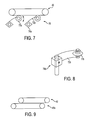
- the pressure assembly 70 of the present invention could take many forms, for example as shown in Figures 3-9.
- the pressure assembly 70 takes the form of a tension bar 72a mounted via suitable mounts 74a, and biased toward drive belt assembly 40 via springs 75a.
- the pressure assembly 70 takes the form of a plurality of leaf springs 72b mounted via suitable mounts 74b, e.g., a mounting block and support rod, such that the flexible leaf springs provide the bias toward drive belt assembly 40.
- the pressure assembly 70 takes the form of a plurality of pivoting idlers 72c biased toward drive belt assembly 40 via spring loaded idler arms 73c, which are mounted via suitable mounts 74c.
- the pressure assembly 70 takes the form of a brush 72d, comprising a bar with bristles, mounted via suitable mounts 74d, such that the bristles provide the bias toward drive belt assembly 40.
- the pressure assembly 70 takes the form of a plurality of leaf springs 72b mounted via suitable mounts 74b, e.g., a mounting block and support rod, as in Figure 4, but further comprising a roller 77b suitably mounted to the end of the leaf spring 72b, as illustrated in Figure 8.
- Figure 9 illustrates an alternate embodiment wherein the pressure assembly 70 takes the form of or is replaced with a second belt assembly 40a mounted in close proximity to the drive belt assembly 40, wherein one or both belt assemblies are driven to propel the mail pieces through the mail piece transport 30. It is also contemplated that a drive roller assembly comprising a plurality of rollers could replace the belt assemblies shown in Figures 1-7 and 9.
- the present invention 10 is suitably located in line with a mail processing machine, such as for example, a mail sorter. Successive mail pieces are fed, on edge, into the mail piece transport 30 of the present invention at a high speed, in any known manner. It should be understood however, that the present invention is capable of weighing mail pieces at any orientation. For example, the mail piece transport could be rotated ninety degrees or set at a certain angle, etc. The mail pieces move between and are supported by the drive belts 60 and the rollers 72. The flange 49 of side plate 48 prevents each mail piece from undesired downward movement.
- the drive belts 60 move the mail pieces through the mail piece transport 30.
- a sensor 90 located upstream of the weighing scale, is operatively connected to the load cell 20.
- the sensor 90 signals the load cell 20 to begin taking weight measurements after the mail piece has traveled a predetermined distance into the mail piece transport 30, providing for a settling time.
- the load cell will measure the weight of both the mail piece transport 30 and the mail piece. By knowing the weight of the mail piece transport 30, the load cell can determine the weight of the mail piece.
- the load cell 20 will take a series of measurements, for example nine, and then a processor in or connected to the load cell 20 will calculate the weight of the mail piece using a predetermined formula for averaging the series of measurements.
- the in-line mail weighing system and scale of the present invention can accurately determine the weight of each mail piece in a stream of mail pieces.
- the mail pieces move through the mail piece transport 30 at a constant high speed.
- the present invention is capable of weighing mail pieces moving through the mail piece transport 30 at a variable speed, or in a stop and start manner.
- the in-line mail weighing system and scale of the present invention is capable of determining the weight of each mail piece within 0.01 of an ounce, at a rate of approximately 14,000 mail pieces per hour.
Landscapes
- Physics & Mathematics (AREA)
- Mathematical Physics (AREA)
- General Physics & Mathematics (AREA)
- Sorting Of Articles (AREA)
Applications Claiming Priority (2)
| Application Number | Priority Date | Filing Date | Title |
|---|---|---|---|
| US10/151,708 US7141745B1 (en) | 2002-05-17 | 2002-05-17 | In-line mail weighing system and scale |
| US151708 | 2002-05-17 |
Publications (1)
| Publication Number | Publication Date |
|---|---|
| EP1362644A1 true EP1362644A1 (de) | 2003-11-19 |
Family
ID=29269816
Family Applications (1)
| Application Number | Title | Priority Date | Filing Date |
|---|---|---|---|
| EP03009856A Withdrawn EP1362644A1 (de) | 2002-05-17 | 2003-05-14 | Anordnung zum in-line Wiegen von Postgut und Waage |
Country Status (3)
| Country | Link |
|---|---|
| US (1) | US7141745B1 (de) |
| EP (1) | EP1362644A1 (de) |
| CA (1) | CA2428553A1 (de) |
Cited By (4)
| Publication number | Priority date | Publication date | Assignee | Title |
|---|---|---|---|---|
| EP2065687A1 (de) * | 2007-11-28 | 2009-06-03 | WIPOTEC Wiege-und Positioniersysteme GmbH | Vorrichtung für den Transport und das Wiegen von Briefen |
| EP2071303A1 (de) * | 2007-12-14 | 2009-06-17 | Pitney Bowes Inc. | Selbstanpassende Hilfskis für eine Wiegevorrichtung |
| DE102007060789A1 (de) * | 2007-12-17 | 2009-06-18 | Francotyp-Postalia Gmbh | Vorrichtung zum Andrücken flacher Güter an ein Transportmodul |
| CN102259767A (zh) * | 2010-05-25 | 2011-11-30 | 株式会社东芝 | 纸张类的重量测定装置和方法、及纸张类处理装置 |
Families Citing this family (6)
| Publication number | Priority date | Publication date | Assignee | Title |
|---|---|---|---|---|
| US7416183B2 (en) * | 2005-06-06 | 2008-08-26 | Pitney Bowes Inc. | Postal weighing platform with integrated feeding and deskewing functions |
| ITTO20070612A1 (it) * | 2007-08-29 | 2009-02-28 | Elsag Datamat Spa | Metodo e dispositivo per determinare la massa di articoli postali trasferiti in successione lungo un percorso |
| DE202008000567U1 (de) * | 2008-01-14 | 2008-03-20 | Wipotec Wiege- Und Positioniersysteme Gmbh | Wägesystem |
| ES2357593B1 (es) * | 2009-01-29 | 2012-03-13 | Girnet International, S.L. | Procedimiento, dispositivo e instalación para el pesaje de sucesivos envases llenos. |
| US8274001B2 (en) * | 2009-12-31 | 2012-09-25 | Mettler-Toledo, LLC | Weighing apparatus having opposed wheels |
| DE102010009431A1 (de) * | 2010-02-24 | 2011-08-25 | Francotyp-Postalia GmbH, 16547 | Schnelle dynamische Waage und Verfahren zur Steuerung einer schnellen dynamischen Waage |
Citations (5)
| Publication number | Priority date | Publication date | Assignee | Title |
|---|---|---|---|---|
| US4137568A (en) | 1977-04-11 | 1979-01-30 | Pitney-Bowes, Inc. | Circuit for establishing the average value of a number of input values |
| US5042015A (en) | 1989-09-01 | 1991-08-20 | Quantronix, Inc. | Measuring method and apparatus |
| US5723825A (en) | 1996-04-01 | 1998-03-03 | Pitney Bowes Inc. | Transport apparatus for a weighing module |
| US6107579A (en) | 1996-02-06 | 2000-08-22 | Siemens Aktiengesellschaft | Arrangement for automatically determining the weight of items of post |
| DE19922881A1 (de) | 1998-07-17 | 2000-11-30 | Francotyp Postalia Gmbh | Vorrichtung zum Wiegen von bewegtem Postgut |
Family Cites Families (8)
| Publication number | Priority date | Publication date | Assignee | Title |
|---|---|---|---|---|
| US4488610A (en) * | 1982-05-17 | 1984-12-18 | Data-Pac Mailing Systems Corp. | Sorting apparatus |
| US4956782A (en) * | 1986-09-19 | 1990-09-11 | Pitney Bowes Inc. | Mailing system for mixed weight mail |
| US5014797A (en) * | 1987-12-17 | 1991-05-14 | Pitney Bowes Inc. | Modular mailing machine |
| US5190115A (en) * | 1990-08-30 | 1993-03-02 | Pitney Bowes Inc. | Modular mailing machine with load cell scale |
| US5094306A (en) * | 1990-12-21 | 1992-03-10 | Pitney Bowes Inc. | Apparatus for controlling the transport mechanism of a weighing scale |
| US5109937A (en) * | 1990-12-21 | 1992-05-05 | Pitney Bowes Inc. | Transport mechanism for a weighing scale |
| US5726393A (en) * | 1994-07-08 | 1998-03-10 | Pitney Bowes Inc. | Fixed transport assembly for mail weighing scale |
| DE19833767C2 (de) * | 1998-07-17 | 2000-07-27 | Francotyp Postalia Gmbh | Vorrichtung zum Wiegen von bewegtem Postgut |
-
2002
- 2002-05-17 US US10/151,708 patent/US7141745B1/en not_active Expired - Fee Related
-
2003
- 2003-05-13 CA CA002428553A patent/CA2428553A1/en not_active Abandoned
- 2003-05-14 EP EP03009856A patent/EP1362644A1/de not_active Withdrawn
Patent Citations (5)
| Publication number | Priority date | Publication date | Assignee | Title |
|---|---|---|---|---|
| US4137568A (en) | 1977-04-11 | 1979-01-30 | Pitney-Bowes, Inc. | Circuit for establishing the average value of a number of input values |
| US5042015A (en) | 1989-09-01 | 1991-08-20 | Quantronix, Inc. | Measuring method and apparatus |
| US6107579A (en) | 1996-02-06 | 2000-08-22 | Siemens Aktiengesellschaft | Arrangement for automatically determining the weight of items of post |
| US5723825A (en) | 1996-04-01 | 1998-03-03 | Pitney Bowes Inc. | Transport apparatus for a weighing module |
| DE19922881A1 (de) | 1998-07-17 | 2000-11-30 | Francotyp Postalia Gmbh | Vorrichtung zum Wiegen von bewegtem Postgut |
Cited By (7)
| Publication number | Priority date | Publication date | Assignee | Title |
|---|---|---|---|---|
| EP2065687A1 (de) * | 2007-11-28 | 2009-06-03 | WIPOTEC Wiege-und Positioniersysteme GmbH | Vorrichtung für den Transport und das Wiegen von Briefen |
| US7900915B2 (en) | 2007-11-28 | 2011-03-08 | Wipotec Wiege-Und Positioniersysteme Gmbh | Device for transporting and weighing letters |
| EP2071303A1 (de) * | 2007-12-14 | 2009-06-17 | Pitney Bowes Inc. | Selbstanpassende Hilfskis für eine Wiegevorrichtung |
| DE102007060789A1 (de) * | 2007-12-17 | 2009-06-18 | Francotyp-Postalia Gmbh | Vorrichtung zum Andrücken flacher Güter an ein Transportmodul |
| EP2072268A3 (de) * | 2007-12-17 | 2010-09-29 | Francotyp-Postalia GmbH | Vorrichtung zum Andrücken flacher Güter an ein Transportmodul |
| US8136813B2 (en) | 2007-12-17 | 2012-03-20 | Francotype-Postalia Gmbh | Apparatus for pressing flat materials onto a transport module |
| CN102259767A (zh) * | 2010-05-25 | 2011-11-30 | 株式会社东芝 | 纸张类的重量测定装置和方法、及纸张类处理装置 |
Also Published As
| Publication number | Publication date |
|---|---|
| US7141745B1 (en) | 2006-11-28 |
| CA2428553A1 (en) | 2003-11-17 |
Similar Documents
| Publication | Publication Date | Title |
|---|---|---|
| AU681214B2 (en) | Conveyor friction scale | |
| US7141745B1 (en) | In-line mail weighing system and scale | |
| GB2195312A (en) | Feeding, weighing and metering mailpieces | |
| EP0534734B1 (de) | Modulare Frankiermaschine mit Wägezellenwaage | |
| CA1292020C (en) | Feeder module | |
| CN111323104A (zh) | 高精度电子皮带秤 | |
| CN114873145B (zh) | 输送和计量装置 | |
| US20030136589A1 (en) | Conveyor belt scale system | |
| CN211168510U (zh) | 基于松软输送带结构的高精度流量称 | |
| EP0512115A1 (de) | Kontrollwaage mit Aerodynamikkorrektur | |
| CN114323217A (zh) | 一种高精度皮带秤 | |
| US20090134568A1 (en) | Device for transporting and weighing letters | |
| US9310241B2 (en) | Device for weighing flat objects in motion | |
| EP2031360B1 (de) | Verfahren und Vorrichtung zur Bestimmung der Masse von aufeinanderfolgenden Postsendungen | |
| US6949710B2 (en) | Mail weighing system and scale apparatus | |
| CN204373755U (zh) | 物料流电子秤 | |
| US8710380B2 (en) | Apparatus and method for weighing an item of mail during transport through a sorting installation and having an anti-vibration device | |
| CN221198613U (zh) | 一种高精度皮带秤 | |
| CN110550384A (zh) | 基于松软输送带结构的高精度流量称 | |
| JP5557885B2 (ja) | コンベヤスケール | |
| CN1188232A (zh) | 检验计重给料机和带秤校准状态的系统 | |
| US7494123B2 (en) | Mechanical device for measuring the width of a mail item | |
| CN219347921U (zh) | 一种安装于装船机尾车机架的称重皮带秤 | |
| US11994423B2 (en) | Weigh belt assembly with a weigh axis that intersects a rotational axis of an idler roller | |
| JP2000266589A (ja) | 搬送機を備えた計量装置 |
Legal Events
| Date | Code | Title | Description |
|---|---|---|---|
| PUAI | Public reference made under article 153(3) epc to a published international application that has entered the european phase |
Free format text: ORIGINAL CODE: 0009012 |
|
| AK | Designated contracting states |
Kind code of ref document: A1 Designated state(s): AT BE BG CH CY CZ DE DK EE ES FI FR GB GR HU IE IT LI LU MC NL PT RO SE SI SK TR |
|
| AX | Request for extension of the european patent |
Extension state: AL LT LV MK |
|
| 17P | Request for examination filed |
Effective date: 20040330 |
|
| AKX | Designation fees paid |
Designated state(s): AT BE BG CH CY CZ DE DK EE ES FI FR GB GR HU IE IT LI LU MC NL PT RO SE SI SK TR |
|
| RAP1 | Party data changed (applicant data changed or rights of an application transferred) |
Owner name: BOWE BELL + HOWELL POSTAL SYSTEMS COMPANY |
|
| 17Q | First examination report despatched |
Effective date: 20090924 |
|
| RAP1 | Party data changed (applicant data changed or rights of an application transferred) |
Owner name: BELL AND HOWELL, LLC |
|
| STAA | Information on the status of an ep patent application or granted ep patent |
Free format text: STATUS: THE APPLICATION IS DEEMED TO BE WITHDRAWN |
|
| 18D | Application deemed to be withdrawn |
Effective date: 20130723 |