EP1362625A1 - Verfahren zur schonenden destillativen Trennung von Stoffgemischen - Google Patents
Verfahren zur schonenden destillativen Trennung von Stoffgemischen Download PDFInfo
- Publication number
- EP1362625A1 EP1362625A1 EP03009997A EP03009997A EP1362625A1 EP 1362625 A1 EP1362625 A1 EP 1362625A1 EP 03009997 A EP03009997 A EP 03009997A EP 03009997 A EP03009997 A EP 03009997A EP 1362625 A1 EP1362625 A1 EP 1362625A1
- Authority
- EP
- European Patent Office
- Prior art keywords
- column
- container
- line
- fraction
- valve
- Prior art date
- Legal status (The legal status is an assumption and is not a legal conclusion. Google has not performed a legal analysis and makes no representation as to the accuracy of the status listed.)
- Withdrawn
Links
- 239000000203 mixture Substances 0.000 title claims abstract description 32
- 238000004821 distillation Methods 0.000 title claims abstract description 26
- 238000000034 method Methods 0.000 title claims description 40
- 239000000126 substance Substances 0.000 title claims description 11
- 238000000926 separation method Methods 0.000 claims abstract description 18
- 238000012856 packing Methods 0.000 claims description 7
- 239000011541 reaction mixture Substances 0.000 claims description 5
- 238000007700 distillative separation Methods 0.000 claims description 4
- 239000011552 falling film Substances 0.000 claims description 4
- 239000007788 liquid Substances 0.000 claims description 4
- 238000001816 cooling Methods 0.000 claims description 3
- 230000014759 maintenance of location Effects 0.000 claims description 3
- 239000011877 solvent mixture Substances 0.000 claims description 3
- 239000010409 thin film Substances 0.000 claims description 2
- 238000011144 upstream manufacturing Methods 0.000 claims description 2
- 238000009835 boiling Methods 0.000 abstract description 24
- IMNFDUFMRHMDMM-UHFFFAOYSA-N N-Heptane Chemical compound CCCCCCC IMNFDUFMRHMDMM-UHFFFAOYSA-N 0.000 description 15
- TVMXDCGIABBOFY-UHFFFAOYSA-N octane Chemical compound CCCCCCCC TVMXDCGIABBOFY-UHFFFAOYSA-N 0.000 description 11
- VLKZOEOYAKHREP-UHFFFAOYSA-N n-Hexane Chemical compound CCCCCC VLKZOEOYAKHREP-UHFFFAOYSA-N 0.000 description 8
- PQSWCVYWEGIBPY-UHFFFAOYSA-N 2,2-dinitroethylbenzene Chemical compound [O-][N+](=O)C([N+]([O-])=O)CC1=CC=CC=C1 PQSWCVYWEGIBPY-UHFFFAOYSA-N 0.000 description 6
- ISWSIDIOOBJBQZ-UHFFFAOYSA-N Phenol Chemical compound OC1=CC=CC=C1 ISWSIDIOOBJBQZ-UHFFFAOYSA-N 0.000 description 6
- QCDWFXQBSFUVSP-UHFFFAOYSA-N 2-phenoxyethanol Chemical compound OCCOC1=CC=CC=C1 QCDWFXQBSFUVSP-UHFFFAOYSA-N 0.000 description 3
- 229960005323 phenoxyethanol Drugs 0.000 description 3
- YNQLUTRBYVCPMQ-UHFFFAOYSA-N Ethylbenzene Chemical compound CCC1=CC=CC=C1 YNQLUTRBYVCPMQ-UHFFFAOYSA-N 0.000 description 2
- 238000010992 reflux Methods 0.000 description 2
- IAYPIBMASNFSPL-UHFFFAOYSA-N Ethylene oxide Chemical compound C1CO1 IAYPIBMASNFSPL-UHFFFAOYSA-N 0.000 description 1
- 238000013459 approach Methods 0.000 description 1
- 230000001174 ascending effect Effects 0.000 description 1
- 238000000998 batch distillation Methods 0.000 description 1
- 238000009529 body temperature measurement Methods 0.000 description 1
- 238000004364 calculation method Methods 0.000 description 1
- 238000006243 chemical reaction Methods 0.000 description 1
- 238000010276 construction Methods 0.000 description 1
- 238000000354 decomposition reaction Methods 0.000 description 1
- 230000003247 decreasing effect Effects 0.000 description 1
- 238000013461 design Methods 0.000 description 1
- 238000005265 energy consumption Methods 0.000 description 1
- 238000005516 engineering process Methods 0.000 description 1
- 238000001704 evaporation Methods 0.000 description 1
- 230000008020 evaporation Effects 0.000 description 1
- 230000002349 favourable effect Effects 0.000 description 1
- 239000000945 filler Substances 0.000 description 1
- 239000010408 film Substances 0.000 description 1
- 238000010438 heat treatment Methods 0.000 description 1
- QWXYZCJEXYQNEI-OSZHWHEXSA-N intermediate I Chemical compound COC(=O)[C@@]1(C=O)[C@H]2CC=[N+](C\C2=C\C)CCc2c1[nH]c1ccccc21 QWXYZCJEXYQNEI-OSZHWHEXSA-N 0.000 description 1
- VJMRKWPMFQGIPI-UHFFFAOYSA-N n-(2-hydroxyethyl)-5-(hydroxymethyl)-3-methyl-1-[2-[[3-(trifluoromethyl)phenyl]methyl]-1-benzothiophen-7-yl]pyrazole-4-carboxamide Chemical compound OCC1=C(C(=O)NCCO)C(C)=NN1C1=CC=CC2=C1SC(CC=1C=C(C=CC=1)C(F)(F)F)=C2 VJMRKWPMFQGIPI-UHFFFAOYSA-N 0.000 description 1
- 238000006396 nitration reaction Methods 0.000 description 1
- 238000004886 process control Methods 0.000 description 1
- 230000002035 prolonged effect Effects 0.000 description 1
- 230000003014 reinforcing effect Effects 0.000 description 1
- 238000007086 side reaction Methods 0.000 description 1
- 238000004088 simulation Methods 0.000 description 1
- 239000002689 soil Substances 0.000 description 1
- 230000008646 thermal stress Effects 0.000 description 1
- 230000001052 transient effect Effects 0.000 description 1
Images

Classifications
-
- B—PERFORMING OPERATIONS; TRANSPORTING
- B01—PHYSICAL OR CHEMICAL PROCESSES OR APPARATUS IN GENERAL
- B01D—SEPARATION
- B01D3/00—Distillation or related exchange processes in which liquids are contacted with gaseous media, e.g. stripping
- B01D3/14—Fractional distillation or use of a fractionation or rectification column
- B01D3/143—Fractional distillation or use of a fractionation or rectification column by two or more of a fractionation, separation or rectification step
-
- B—PERFORMING OPERATIONS; TRANSPORTING
- B01—PHYSICAL OR CHEMICAL PROCESSES OR APPARATUS IN GENERAL
- B01D—SEPARATION
- B01D3/00—Distillation or related exchange processes in which liquids are contacted with gaseous media, e.g. stripping
- B01D3/14—Fractional distillation or use of a fractionation or rectification column
-
- B—PERFORMING OPERATIONS; TRANSPORTING
- B01—PHYSICAL OR CHEMICAL PROCESSES OR APPARATUS IN GENERAL
- B01D—SEPARATION
- B01D3/00—Distillation or related exchange processes in which liquids are contacted with gaseous media, e.g. stripping
- B01D3/14—Fractional distillation or use of a fractionation or rectification column
- B01D3/32—Other features of fractionating columns ; Constructional details of fractionating columns not provided for in groups B01D3/16 - B01D3/30
- B01D3/322—Reboiler specifications
-
- Y—GENERAL TAGGING OF NEW TECHNOLOGICAL DEVELOPMENTS; GENERAL TAGGING OF CROSS-SECTIONAL TECHNOLOGIES SPANNING OVER SEVERAL SECTIONS OF THE IPC; TECHNICAL SUBJECTS COVERED BY FORMER USPC CROSS-REFERENCE ART COLLECTIONS [XRACs] AND DIGESTS
- Y10—TECHNICAL SUBJECTS COVERED BY FORMER USPC
- Y10S—TECHNICAL SUBJECTS COVERED BY FORMER USPC CROSS-REFERENCE ART COLLECTIONS [XRACs] AND DIGESTS
- Y10S203/00—Distillation: processes, separatory
- Y10S203/07—Start up or shut down
-
- Y—GENERAL TAGGING OF NEW TECHNOLOGICAL DEVELOPMENTS; GENERAL TAGGING OF CROSS-SECTIONAL TECHNOLOGIES SPANNING OVER SEVERAL SECTIONS OF THE IPC; TECHNICAL SUBJECTS COVERED BY FORMER USPC CROSS-REFERENCE ART COLLECTIONS [XRACs] AND DIGESTS
- Y10—TECHNICAL SUBJECTS COVERED BY FORMER USPC
- Y10S—TECHNICAL SUBJECTS COVERED BY FORMER USPC CROSS-REFERENCE ART COLLECTIONS [XRACs] AND DIGESTS
- Y10S203/00—Distillation: processes, separatory
- Y10S203/13—Spirits
Definitions
- the invention relates to a method for gentle separation by distillation Mixtures in semi-batch mode.
- the separation of two and in particular more than two components are frequently used, the first is the Distillation bubble filled with the mixture to be separated and up to the boiling point heated. Subsequently, the fractions may be in ascending order of their Boiling point are taken over the top of the column, at the same time the Sump temperature rises.
- EP-A 638 345 a column with one container each at the sump and at the top described, which used depending on the desired driving as amplifier or driven part can be.
- the distillation times can in this way be reduced.
- this method is complex in terms of apparatus and not generally applicable.
- Baichun and Zhicai (Huagong Gongcheng, 22, 1994, pp. 30-34) describe the Separation of a multicomponent system in a two-vessel column.
- n-1 decomposes continuous steps to separate a mixture with n fractions.
- a container is needed as a feed tank and a second to the sump drain take.
- This driving style allows the simultaneous use of the Column as output and amplifier part and thus an acceptable specific Power consumption.
- an additional container is also for this process necessary.
- Maczynski and Maczynska (Przemysl Chemiczny 49, 1970, pp. 599-601) suggest The separation of a binary mixture is a procedure that has the advantages of continuous and the discontinuous driving style combined. It is in a first step the column, at the lower end of which is a distillation bubble is charged with a continuous feed and over the top of the column taken the first fraction. The sump drain is used to make the distillation bubble to fill. Also in this process, the contents of the distillation still be kept at boiling temperature, so that the thermal load of heavy boiling components is very high.
- the invention also encompasses a method in which steps a) and b) are or be repeated several times.
- step a the column is continuously charged with an inlet.
- continuous also excludes changes in the feed rate over time a like temporary interruptions of the inlet, as for example at intervalwise or stepped or changing over a predetermined ramp Feed to be realized.
- the feed point is chosen so that the column has a stripping section and has an amplifier part.
- the columns known to those skilled in the art can be used.
- the column can also be used as a dividing wall column or be configured thermally coupled column.
- the column both with trays and with packing elements equip.
- the reinforcing part packs and in the Stripping section floors are used.
- soils, packing and Packs are available in, for example, Henry Kister, Distillation Design, McGrawHill, 1992, K. Sattler, Thermal Separation Technology, Verlag VCH, 2001.
- the number of theoretical plates in the column can be 2 to 150, preferably 4 to 70, particularly preferably 6 to 60.
- a part of the to be separated Substance mixture can be used or a fraction of it, for example can come from a previous separation.
- the column of the column is being filled with so much liquid, that the evaporator can be put into operation.
- the column with a high boiler fraction of the to be separated Approach mixture to the content of low boilers in the column bottom to keep it as low as possible from the outset.
- high boiler and “high boiler fractions” are such substances or mixtures of substances which have a higher boiling point than those which may be present existing medium boilers and medium boiler fractions, which in turn a have higher boiling point than the low boilers and low boiler fractions.
- terms refer to a sub-step and can be used for Step a) and step b) have different meanings for a single substance. For example, a high boiler from step a) in step b) a low boiler his.
- the feed is at least in a low-boiling fraction and a high boiler fraction and optionally a medium boiler fraction separated, wherein one of the fractions continuously discharged into a container becomes.
- step a) at least one low boiler fraction is preferably passed over the Column head and at least one high boiler fraction over the column bottom taken.
- step a) is a low boiler fraction via the top of the column (also top fraction), a medium boiler fraction over a side stream (also Side stream fraction) and a high boiler fraction over the column bottom (also Bottom fraction).
- Step a) a low boiler fraction over the top of the column and a high boiler fraction taken from the bottom of the column.
- It can either be a top fraction, optionally a medium boiler fraction or a bottoms fraction are transferred to the container, preferably the top fraction or the bottom fraction.
- That fraction is discharged into the container whose purity requirements not be fulfilled in the continuous step.
- the discharge into the container takes place continuously, the term being continuous as defined above.
- the fraction that is discharged into the container is staying at a temperature based on the column bottom pressure is below its boiling point and therefore, for example, in comparison to the discontinuous Distillation is significantly less thermally stressed.
- the removal and the retention in the container takes place without additional Heat supply or under cooling.
- the residence temperature can vary depending on the product properties to get voted.
- step a) the process according to the invention takes place in step a) depending on the desired target purity the head or sump product, the control of suitable temperature measurements in the amplifier and / or output part.
- step a) by stopping the feed finished and fed in step b), the contents of the container of the column. in the Step b), the column may optionally be down, up or down and down simultaneously be driven upwards.
- the freedom of connection in step b) requires that the Column not directly to the boiler, but preferably via a pipeline with liquid closure, for example with a shut-off device, connected is.
- the container In the downward driving mode, the container is connected to the condensate drain, and the container drain goes as reflux to the top of the column.
- the fractions are withdrawn as high boiler fractions at the swamp, until the end of the last Low-boiling fraction remains in the container in the desired purity.
- step b) the mixture becomes discontinuous in the upwards mode separated.
- the container is then incorporated into the sump circuit, wherein the liquid from the sump over the container and the evaporator back into the Column is led.
- Overhead are one or more low boiler fractions subtracted until the last high boiler fraction in the desired purity in the container is. This may also be the distillation residue.
- step b) may be through a connection of the container in the middle of the column can be realized. It will be both at the top of low-boiling fractions and at the swamp high-boiling fractions removed.
- This embodiment of step b) is advantageously terminated when a Medium boiler fraction - or alternatively an intermediate cut - in the desired Purity / composition is left in the container.
- the batch distillation with center tank is described, for example, in M. Warter et al., Comp. Chem. Eng. Suppl. (1999) p. 915-S. 918th
- a heating with direct steam is possible.
- Upward driving can be evaporated from the container.
- the container can for gentle treatment of the input products be operated at a temperature below the boiling temperature.
- an evaporator As an evaporator all known to the expert evaporator types can be used, the one require low temperature increase and evaporation from thin layers / films enable. Preference is given to falling-film evaporators or thin-film evaporators used.
- the evaporator one or more Preheater be upstream.
- the scope of the invention also encompasses a method in which the steps a) and b) are each repeated one or more times independently.
- the inventive method is particularly suitable for the separation of Multi-component mixtures.
- multicomponent mixtures are reaction mixtures or solvent mixtures.
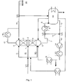
- the column 2 is mixed with the components A to be separated mixture (lowest boiling point), B (middle boiling point), C (highest boiling point) above a Inlet valve V1 and the inlet 1, which can be located in the upper (i), middle (ii) or in the lower part of the column, continuously charged.
- a Inlet valve V1 At the feed the column 2 over the middle part (ii), as shown in Figure 2, is the column 2 consequently for step a) in a stripping 4 and an amplifier part. 3 separated.
- component A is removed via the column head 5 and the Components B and C via the column bottom 6 and via the lines 7 and 9 and the intermediate valve (V2) and the heat exchanger 9 at least partially discharged into a container 10.
- the inlet valve V1 is closed.
- Column 5 At the top of the column 5 is the low boilers of the mixture B in the desired purity via the line 19 in a collecting device 20 subtracted. In the bottom of the high boiler C is concentrated.
- Step is completed when C has reached the desired target purity.
- Optional can also components B and C via the inlet 1 back to the column 2, the component B via the column head 5 and the component C over the bottom of the column 6, but then in a separate product container.
- the scope of the invention also encompasses a method in which the steps a) and b) are each repeated one or more times independently.
- the inventive method is particularly suitable for the separation of Multi-component mixtures.
- multicomponent mixtures are reaction mixtures or solvent mixtures.
- the invention further comprises a distillation apparatus consisting at least from a column 2, from the upper part 5 a derivative 17 via a heat exchanger 18 and a line 19 leads to a valve V4, wherein the Line 19 is connected to the column and further to at least one collecting device 20 leads, a controllable via an inlet valve V1 inlet 1, the in the column opens, and one of the column spatially separated, temperature-controlled Container 10, which is connected via lines 7 and 9 to the column, the characterized in that the conduit 7 leads to a valve V2, via the Line 9, which optionally leads via a heat exchanger 8, with the container 10 and is connected via the line 11 to the valve V3, wherein the valve V3 via the line 12 to the container and via the line 13 to the column and wherein the conduit 13 further comprises a pump 14, optionally includes a preheater 15 and optionally an evaporator 16, and further the attached at the upper end of the column 2 line 19 includes a valve V4, the column 2 connects via the line 19 and the line 21 to the container 10.
- the present invention is characterized in that the entire process can be carried out under little equipment. Furthermore you can in particular mixtures with thermally sensitive fractions in very good Space-time yields are gently separated.
- the separation was once discontinuously from a distillation bubble with attached Column (I) and according to the invention (II) performed.
- the comparison is based on Simulation calculations, but on the basis of a measured substance system and with a validated column model.
- the feed point was chosen so that the column 2 both an output part and an amplifier part (ii).
- the column is a header over head taken, whose phenol content is controlled.
- the bottom outlet of the column 6 is fed into the container 10.
- the container was the inlet by switching the inlet valve V1 stopped and immediately moved to step b) and taken further forward.
- the phenol content decreased in the flow, and falls below a certain salary depending on the quality requirements of the main run Phenol was switched to main run.
- the main run was removed and then on converted total return.
- the apparatus was then ready to take over next batch. After six batches, it was collected in the still Swamp discharged after rectification by a phenoxyethanol and higher homologues containing fraction has separated in the wake.
- step a) the column 2 was continuously from a reaction mixture the nitration of ethylbenzene, which is essentially ortho- and para-nitroethylbenzene (o-NEB or p-NEB) and about 7% meta-nitroethylbenzene (m-NEB) and 0.5% dinitroethylbenzene (Di-NEB). It was about the Column head 5 is the mixture of o-NEB, p-NEB and m-NEB freed from Di-NEB removed and discharged into the container 10. Over the column sump 6 became taken a fraction containing about 10% by weight of Di-NEB.
- o-NEB or p-NEB essentially ortho- and para-nitroethylbenzene
- m-NEB meta-nitroethylbenzene
- Di-NEB dinitroethylbenzene
- step b) the column 2 was removed from the container 10 with the product obtained in step a) Mixture of o-NEB, p-NEB and m-NEB fed. It was about the Column head 5 consecutively the fractions flow, o-NEB, intermediate I and Intermediate II taken. Since Di-NEB and other high boilers already in step a) were removed, the pure p-NEB was present in the swamp. Optionally, one follows Post-distillation with decrease of pure p-NEB overhead.
Landscapes
- Chemical & Material Sciences (AREA)
- Chemical Kinetics & Catalysis (AREA)
- Organic Low-Molecular-Weight Compounds And Preparation Thereof (AREA)
- Vaporization, Distillation, Condensation, Sublimation, And Cold Traps (AREA)
Abstract
Description
100 kg n-Hexan
700 kg n-Heptan
200 kg n-Oktan
ohne Zwischenschnitt getrennt, wobei die Reinheit jeweils mindestens 99,0 % betrug.
Claims (18)
- Verfahren zur destillativen Trennung von Stoffgemischen, dadurch gekennzeichnet, dassa) eine Kolonne kontinuierlich mit einem Zulauf beaufschlagt wird und der Zulauf zumindest in eine Leichtsiederfraktion und eine Schwersiederfraktion getrennt wird und wobei eine der Fraktionen kontinuierlich in einen Behälter abgeführt wird undb) nach Stoppen des Zulaufs die in Schritt a) in den Behälter abgeführte Fraktion der gleichen Kolonne wieder zugeführt und erneut zumindest in eine Leichtsiederfraktion und eine Schwersiederfraktion getrennt wird.
- Verfahren nach Anspruch 1, dadurch gekennzeichnet, dass der Zulauf in Schritt a) zumindest in eine Leichtsiederfraktion, eine Mittelsiederfraktion und eine Schwersiederfraktion getrennt wird und in Schritt b) die in Schritt a) in den Behälter abgeführte Fraktion erneut zumindest in eine Leichtsiederfraktion, eine Mittelsiederfraktion und eine Schwersiederfraktion getrennt wird.
- Verfahren nach einem oder mehreren der Ansprüche 1 bis 2, dadurch gekennzeichnet, dass der Schritt a) und/oder Schritt b) unabhängig voneinander einoder mehrfach wiederholt werden.
- Verfahren nach einem oder mehreren der Ansprüche 1 bis 3, dadurch gekennzeichnet, dass die Kolonne gleichzeitig als Abtriebs- und Verstärkerkolonne genutzt wird.
- Verfahren nach einem oder mehreren der Ansprüche 1 bis 4, dadurch gekennzeichnet, dass als Kolonne Füllkörper oder geordnete Packungen enthaltende Packungskolonnen oder Bodenkolonnen, Trennwandkolonnen oder thermisch gekoppelte Kolonnen verwendet werden.
- Verfahren nach einem oder mehreren der Ansprüche 1 bis 5, dadurch gekennzeichnet, dass die Kolonne 2 bis 150 theoretischenTrennstufen besitzt.
- Verfahren nach einem oder mehreren der Ansprüche 1 bis 6, dadurch gekennzeichnet, dass zum Anfahren der Kolonne der Sumpf der Kolonne gerade mit so viel Flüssigkeit befüllt wird, dass der Verdampfer in Betrieb genommen werden kann.
- Verfahren nach einem oder mehreren der Ansprüche 1 bis 7, dadurch gekennzeichnet, dass zum Anfahren der Kolonne eine Schwersiederfraktion des zu trennenden Stoffgemisches verwendet wird.
- Verfahren nach einem oder mehreren der Ansprüche 1 bis 8, dadurch gekennzeichnet, dass die Abführung und das Verweilen der abgeführten Fraktion im Behälter ohne zusätzliche Wärmezufuhr oder unter Kühlung erfolgt.
- Verfahren nach einem oder mehreren der Ansprüche 1 bis 9, dadurch gekennzeichnet, dass das Verweilen der abgeführten Fraktion im Behälter unter Kühlung erfolgt.
- Verfahren nach einem oder mehreren der Ansprüche 1 bis 10, dadurch gekennzeichnet, dass Schritt a) automatisiert durchgeführt wird.
- Verfahren nach einem oder mehreren der Ansprüche 1 bis 11, dadurch gekennzeichnet, dass im Schritt b) die Kolonne abwärts, aufwärts oder simultan abwärts und aufwärts gefahren wird.
- Verfahren nach einem oder mehreren der Ansprüche 1 bis 12, dadurch gekennzeichnet, dass die Kolonne sowohl im Schritt a) als auch im Schritt b) simultan abwärts und aufwärts gefahren wird.
- Verfahren nach einem oder mehreren der Ansprüche 1 bis 13, dadurch gekennzeichnet, dass im Schritt b) die Beschickung der Kolonne aus dem Behälter über einen Verdampfer erfolgt.
- Verfahren nach Anspruch 14, dadurch gekennzeichnet, dass als Verdampfer Fallfilmverdampfer oder Dünnschichtverdampfer eingesetzt werden.
- Verfahren nach einem oder mehreren der Ansprüche 1 bis 15, dadurch gekennzeichnet, dass dem Verdampfer ein oder mehrere Vorwärmer vorgeschaltet sind.
- Verfahren nach einem oder mehreren der Ansprüche 1 bis 16, dadurch gekennzeichnet, dass als Zulauf Reaktionsgemische oder Lösungsmittelgemische eingesetzt werden.
- Destillationsvorrichtung, bestehend wenigstens aus einer Kolonne (2), aus deren oberem Teil (5) eine Ableitung (17) über einen Wärmetauscher (18) und eine Leitung (19) an ein Ventil (V4) führt, wobei die Leitung (19) mit der Kolonne verbunden ist und weiterhin zu mindestens einer Sammelvorrichtung (20) führt, einem über ein Zulaufventil (V1) steuerbaren Zulauf (1), der in die Kolonne mündet, und einem von der Kolonne räumlich getrennten temperierbaren Behälter (10), der über die Leitungen (7) und (9) mit der Kolonne verbunden ist, dadurch gekennzeichnet, dass die Leitung (7) an ein Ventil (V2) führt, das über die Leitung (9), die gegebenenfalls über einen Wärmetauscher (8) führt, mit dem Behälter (10) und über die Leitung (11) mit dem Ventil (V3) verbunden ist, wobei das Ventil (V3) über die Leitung (12) mit dem Behälter und über die Leitung (13) mit der Kolonne verbunden ist und wobei die Leitung (13) weiterhin eine Pumpe (14), gegebenenfalls einen Vorwärmer (15) und gegebenenfalls einen Verdampfer (16) enthält und weiterhin die am oberen Ende der Kolonne (2) angebrachte Leitung (19) ein Ventil (V4) enthält, das die Kolonne (2) über die Leitung (19) und die Leitung (21) mit dem Behälter (10) verbindet.
Applications Claiming Priority (2)
| Application Number | Priority Date | Filing Date | Title |
|---|---|---|---|
| DE10221122A DE10221122A1 (de) | 2002-05-13 | 2002-05-13 | Verfahren zur schonenden destillativen Trennung von Stoffgemischen |
| DE10221122 | 2002-05-13 |
Publications (1)
| Publication Number | Publication Date |
|---|---|
| EP1362625A1 true EP1362625A1 (de) | 2003-11-19 |
Family
ID=29265251
Family Applications (1)
| Application Number | Title | Priority Date | Filing Date |
|---|---|---|---|
| EP03009997A Withdrawn EP1362625A1 (de) | 2002-05-13 | 2003-05-02 | Verfahren zur schonenden destillativen Trennung von Stoffgemischen |
Country Status (5)
| Country | Link |
|---|---|
| US (2) | US7435319B2 (de) |
| EP (1) | EP1362625A1 (de) |
| JP (1) | JP2004066222A (de) |
| CN (1) | CN1309439C (de) |
| DE (1) | DE10221122A1 (de) |
Cited By (2)
| Publication number | Priority date | Publication date | Assignee | Title |
|---|---|---|---|---|
| WO2017005565A1 (de) * | 2015-07-03 | 2017-01-12 | Basf Se | Destillationseinrichtung umfassend eine kolonne, mit drei oder mehreren hintereinander flüssigkeitsdurchströmten zellen und verfahren zur destillation oder extraktivdestillation unter verwendung der destillationseinrichtung |
| CN106693431A (zh) * | 2017-03-17 | 2017-05-24 | 河南中托力合化学有限公司 | 新型庚烷精密分馏装置 |
Families Citing this family (13)
| Publication number | Priority date | Publication date | Assignee | Title |
|---|---|---|---|---|
| JP4500077B2 (ja) * | 2004-03-24 | 2010-07-14 | 四日市合成株式会社 | 高純度フェノール・酸化エチレン付加体の製造法 |
| JP4500076B2 (ja) * | 2004-03-24 | 2010-07-14 | 四日市合成株式会社 | 高純度フェノール・酸化エチレン付加体の製造方法 |
| US7525004B2 (en) * | 2007-05-23 | 2009-04-28 | Uop Llc | Process for producing ethylbenzene |
| US7713386B2 (en) * | 2007-05-23 | 2010-05-11 | Uop Llc | Apparatus for producing ethylbenzene or cumene |
| US7498471B2 (en) * | 2007-05-23 | 2009-03-03 | Uop Llc | Process for producing cumene |
| US7525006B2 (en) * | 2007-05-23 | 2009-04-28 | Uop Llc | Process for producing cumene |
| US7525005B2 (en) * | 2007-05-23 | 2009-04-28 | Uop Llc | Process for producing cumene |
| US7498472B2 (en) * | 2007-05-23 | 2009-03-03 | Uop Llc | Process for producing ethylbenzene |
| US7525003B2 (en) * | 2007-05-23 | 2009-04-28 | Uop Llc | Process for producing ethylbenzene |
| CA2706104C (en) | 2010-06-17 | 2011-11-22 | Poutrelles Modernes Ltee | Top-chord bearing joist |
| WO2016209741A1 (en) * | 2015-06-23 | 2016-12-29 | Joshi Rohit D | Method for recycling liquid waste |
| KR102670910B1 (ko) * | 2021-03-16 | 2024-05-29 | 한화솔루션 주식회사 | 증발기 및 이를 이용한 분리 방법 |
| CN113617041B (zh) * | 2021-07-21 | 2022-11-29 | 邳州市鑫盛创业投资有限公司 | 一种酒精加工用再沸器 |
Citations (3)
| Publication number | Priority date | Publication date | Assignee | Title |
|---|---|---|---|---|
| US5223101A (en) * | 1991-02-22 | 1993-06-29 | Phillips Petroleum Company | Low color, low turbidity sulfolane |
| DE4226905A1 (de) * | 1992-08-14 | 1994-02-17 | Basf Ag | Verfahren zur Durchführung von destillativen Trennungen in diskontinuierlicher Betriebsweise |
| US5705039A (en) * | 1995-10-13 | 1998-01-06 | Albemarle Corporation | Process for purifying a 2,6-dialkylphenol |
Family Cites Families (16)
| Publication number | Priority date | Publication date | Assignee | Title |
|---|---|---|---|---|
| US2939293A (en) * | 1958-04-07 | 1960-06-07 | Phillips Petroleum Co | Start-up procedure-gas fractionator |
| US3493468A (en) * | 1966-03-24 | 1970-02-03 | Giovanni Mascarini Soc Ing | Apparatus for automatic starting and control of vapor compression distillation |
| US3666633A (en) * | 1969-10-28 | 1972-05-30 | Du Pont | Recovery of chlorinated alkane solvent |
| US4568356A (en) * | 1978-11-09 | 1986-02-04 | Chambers John M | Process for making anhydrous alcohol for mixing with gasoline to make gasohol motor fuel |
| JPS5688791A (en) * | 1979-12-22 | 1981-07-18 | Tsukishima Kikai Co Ltd | Distillation device for ethyl alcohol with added salt |
| DE3446265A1 (de) * | 1984-12-19 | 1986-06-19 | Haarmann & Reimer Gmbh, 3450 Holzminden | Verfahren zur reinigung von rohem ss-phenylethylalkohol |
| DE3725925A1 (de) * | 1987-08-05 | 1989-02-16 | Basf Ag | Verfahren zur gewinnung von n-ethylpiperazin |
| US5059288A (en) * | 1989-11-21 | 1991-10-22 | Harborchem | Recovery of isopropyl acetate and ethanol from an isopropyl acetate, ethanol and water-containing stream |
| US5268073A (en) * | 1990-04-07 | 1993-12-07 | Bayer Aktiengesellschaft | Continuous process for concentrating solutions containing salts and resins |
| US5443695A (en) * | 1993-02-26 | 1995-08-22 | Athens Corporation | Distillation apparatus for concentrating less volatile liquids |
| US5374767A (en) * | 1993-04-15 | 1994-12-20 | E. I. Du Pont De Nemours And Company | Process for the production of cyclohexyladipates and adipic acid |
| ES2108909T5 (es) | 1993-07-08 | 2001-08-01 | Basf Ag | Procedimiento para la realizacion de separaciones mediante destilacion en modo de operacion discontinuo. |
| DE19602640A1 (de) * | 1996-01-25 | 1997-07-31 | Basf Ag | Verfahren und Verdampfer zur Verdampfung oxidationsempfindlicher Verbindungen |
| NL1007442C2 (nl) * | 1997-11-04 | 1998-12-07 | Josephus Johannes Petrus Maria | Batch-Continue tegenstroomapparatuur met superieure performance. |
| US6982026B2 (en) * | 2001-03-15 | 2006-01-03 | Tate & Lyle Ingredients Americas, Inc. | Azeotropic distillation process for producing organic acids or organic acid amides |
| US6550274B1 (en) * | 2001-12-05 | 2003-04-22 | Air Products And Chemicals, Inc. | Batch distillation |
-
2002
- 2002-05-13 DE DE10221122A patent/DE10221122A1/de not_active Withdrawn
-
2003
- 2003-05-02 EP EP03009997A patent/EP1362625A1/de not_active Withdrawn
- 2003-05-12 US US10/435,886 patent/US7435319B2/en not_active Expired - Fee Related
- 2003-05-13 CN CNB031312950A patent/CN1309439C/zh not_active Expired - Fee Related
- 2003-05-13 JP JP2003135039A patent/JP2004066222A/ja active Pending
-
2008
- 2008-09-09 US US12/206,898 patent/US20090032389A1/en not_active Abandoned
Patent Citations (3)
| Publication number | Priority date | Publication date | Assignee | Title |
|---|---|---|---|---|
| US5223101A (en) * | 1991-02-22 | 1993-06-29 | Phillips Petroleum Company | Low color, low turbidity sulfolane |
| DE4226905A1 (de) * | 1992-08-14 | 1994-02-17 | Basf Ag | Verfahren zur Durchführung von destillativen Trennungen in diskontinuierlicher Betriebsweise |
| US5705039A (en) * | 1995-10-13 | 1998-01-06 | Albemarle Corporation | Process for purifying a 2,6-dialkylphenol |
Cited By (3)
| Publication number | Priority date | Publication date | Assignee | Title |
|---|---|---|---|---|
| WO2017005565A1 (de) * | 2015-07-03 | 2017-01-12 | Basf Se | Destillationseinrichtung umfassend eine kolonne, mit drei oder mehreren hintereinander flüssigkeitsdurchströmten zellen und verfahren zur destillation oder extraktivdestillation unter verwendung der destillationseinrichtung |
| US10569192B2 (en) | 2015-07-03 | 2020-02-25 | Basf Se | Distillation device comprising a column which as three or a plurality of cells in series through which fluid flows and method for distilling or extractive distillation by use of the distillation device |
| CN106693431A (zh) * | 2017-03-17 | 2017-05-24 | 河南中托力合化学有限公司 | 新型庚烷精密分馏装置 |
Also Published As
| Publication number | Publication date |
|---|---|
| CN1309439C (zh) | 2007-04-11 |
| JP2004066222A (ja) | 2004-03-04 |
| US20090032389A1 (en) | 2009-02-05 |
| US20040020757A1 (en) | 2004-02-05 |
| CN1457913A (zh) | 2003-11-26 |
| DE10221122A1 (de) | 2003-12-04 |
| US7435319B2 (en) | 2008-10-14 |
Similar Documents
| Publication | Publication Date | Title |
|---|---|---|
| DE10221122A1 (de) | Verfahren zur schonenden destillativen Trennung von Stoffgemischen | |
| EP0082316B1 (de) | Verfahren zur Herstellung von Methyl-Tert.-butylether (MTBE) und weitgehend von i-Buten und von Methanol befreiten Kohlenwasserstoff-Raffinaten und Vorrichtung hierfür | |
| EP1339658B1 (de) | Verfahren und vorrichtung zur destillativen gewinnung von 1,3-reinbutadien aus 1,3-rohbutadien | |
| DE3142518C2 (de) | ||
| DE19616842B4 (de) | Verfahren zur Herstellung von 1-Buten durch Dimerisierung von Ethylen, das eine verbesserte Rückgewinnungszone von verbrauchtem Katalysator umfaßt | |
| EP0073945A1 (de) | Verfahren zur Gewinnung reiner Aromaten | |
| EP0046876B1 (de) | Verfahren zur Aufarbeitung des Sumpfproduktes von Extraktivdestillationsprozessen zur Gewinnung reiner Kohlenwasserstoffe | |
| DE10144239A1 (de) | Verfahren zur Prozeßführung einer Extraktivdestillationsanlage, Prozeßleitsystem und Extraktivdestillationsanlage | |
| EP0638345B1 (de) | Verfahren zur Durchführung von destillativen Trennungen in diskontinuierlicher Betriebsweise | |
| EP3555038B1 (de) | Verfahren zur destillativen gewinnung von reinem cyclohexyl(meth)acrylat | |
| DE2000822A1 (de) | Verfahren zur Herstellung von Adiponitril | |
| DE914130C (de) | Verfahren zur Herstellung von gesaettigten Kohlenwasserstoffen mit verzweigten Ketten | |
| EP0086890A1 (de) | Verfahren zur Trennung von Gemischen aus Paraffin bzw. Paraffinen mit 6 bis 14 C-Atomen und Alkohol bzw. Alkoholen mit 4 bis 8 C-Atomen | |
| EP0017774B1 (de) | Verfahren zur Regelung der einer Extraktivdestillationskolonne am Sumpf zugeführten Wärmemenge | |
| EP0505723B1 (de) | Verfahren zur Abtrennung von Aromaten durch Extraktivdestillation | |
| EP0864556B1 (de) | Verfahren zur Herstellung von hochreinem Cyclopropylmethylketon | |
| DE2350127B2 (de) | Kontinuierliches Verfahren zur Abtrennung von Benzol, Toluol und gegebenenfalls Xylolen aus Kohlenwasserstoffbeschickungen | |
| DE3437615C2 (de) | ||
| DE69405290T2 (de) | Verfahren zur Herstellung von Diacetoxybuten | |
| DE1805957A1 (de) | Verfahren zur Reinigung von Xylylendiisocyanat | |
| DE2105017B2 (de) | Kontinuierliches Verfahren zur Herstellung von Dimethylterephthalat | |
| EP1576995A2 (de) | Verfahren zur kontinuierlichen Zerlegung von Stoffgemischen | |
| AT206090B (de) | Verfahren zur Herstellung von Benzinkohlenwasserstoffen von hohem Antiklopfwert | |
| DE623875C (de) | Verfahren zur Rektifikation von Fluessigkeiten | |
| DE2759846C2 (de) | Verfahren zum Entgasen, Entwässern und Desodorieren von Fettrohsäuren |
Legal Events
| Date | Code | Title | Description |
|---|---|---|---|
| PUAI | Public reference made under article 153(3) epc to a published international application that has entered the european phase |
Free format text: ORIGINAL CODE: 0009012 |
|
| AK | Designated contracting states |
Kind code of ref document: A1 Designated state(s): AT BE BG CH CY CZ DE DK EE ES FI FR GB GR HU IE IT LI LU MC NL PT RO SE SI SK TR |
|
| AX | Request for extension of the european patent |
Extension state: AL LT LV MK |
|
| RAP1 | Party data changed (applicant data changed or rights of an application transferred) |
Owner name: BAYER CHEMICALS AG |
|
| 17P | Request for examination filed |
Effective date: 20040519 |
|
| AKX | Designation fees paid |
Designated state(s): AT BE BG CH CY CZ DE DK EE ES FI FR GB GR HU IE IT LI LU MC NL PT RO SE SI SK TR |
|
| 17Q | First examination report despatched |
Effective date: 20041019 |
|
| RAP1 | Party data changed (applicant data changed or rights of an application transferred) |
Owner name: LANXESS DEUTSCHLAND GMBH |
|
| 17Q | First examination report despatched |
Effective date: 20041019 |
|
| STAA | Information on the status of an ep patent application or granted ep patent |
Free format text: STATUS: THE APPLICATION IS DEEMED TO BE WITHDRAWN |
|
| 18D | Application deemed to be withdrawn |
Effective date: 20090224 |