EP1362443B1 - Komponentenweise regelung der stralungsleistung in optischen wellenlängenmultiplex-nachrichtenübertragungssystemen - Google Patents
Komponentenweise regelung der stralungsleistung in optischen wellenlängenmultiplex-nachrichtenübertragungssystemen Download PDFInfo
- Publication number
- EP1362443B1 EP1362443B1 EP02712057A EP02712057A EP1362443B1 EP 1362443 B1 EP1362443 B1 EP 1362443B1 EP 02712057 A EP02712057 A EP 02712057A EP 02712057 A EP02712057 A EP 02712057A EP 1362443 B1 EP1362443 B1 EP 1362443B1
- Authority
- EP
- European Patent Office
- Prior art keywords
- token
- node
- nodes
- power
- optical
- Prior art date
- Legal status (The legal status is an assumption and is not a legal conclusion. Google has not performed a legal analysis and makes no representation as to the accuracy of the status listed.)
- Expired - Lifetime
Links
- 230000003287 optical effect Effects 0.000 title claims abstract description 143
- 238000004891 communication Methods 0.000 title claims abstract description 61
- 230000001105 regulatory effect Effects 0.000 title claims abstract description 32
- 230000005855 radiation Effects 0.000 title abstract description 81
- 238000000034 method Methods 0.000 claims abstract description 36
- 230000004044 response Effects 0.000 claims abstract description 10
- 230000001902 propagating effect Effects 0.000 claims description 16
- 230000000977 initiatory effect Effects 0.000 claims description 5
- 239000013307 optical fiber Substances 0.000 abstract description 4
- 239000000835 fiber Substances 0.000 description 14
- 230000001276 controlling effect Effects 0.000 description 6
- 238000003491 array Methods 0.000 description 5
- 230000003534 oscillatory effect Effects 0.000 description 3
- 230000003321 amplification Effects 0.000 description 2
- 238000013479 data entry Methods 0.000 description 2
- 238000003199 nucleic acid amplification method Methods 0.000 description 2
- 230000009286 beneficial effect Effects 0.000 description 1
- 230000008901 benefit Effects 0.000 description 1
- 230000005540 biological transmission Effects 0.000 description 1
- 238000013461 design Methods 0.000 description 1
- 238000010586 diagram Methods 0.000 description 1
- 230000005670 electromagnetic radiation Effects 0.000 description 1
- 238000001914 filtration Methods 0.000 description 1
- 230000006870 function Effects 0.000 description 1
- 238000002955 isolation Methods 0.000 description 1
- 238000012804 iterative process Methods 0.000 description 1
- 239000011159 matrix material Substances 0.000 description 1
- 238000005259 measurement Methods 0.000 description 1
- 238000012986 modification Methods 0.000 description 1
- 230000004048 modification Effects 0.000 description 1
- 238000012544 monitoring process Methods 0.000 description 1
- 230000005693 optoelectronics Effects 0.000 description 1
- 230000010355 oscillation Effects 0.000 description 1
- 230000008569 process Effects 0.000 description 1
- 230000002269 spontaneous effect Effects 0.000 description 1
Images

Classifications
-
- H—ELECTRICITY
- H04—ELECTRIC COMMUNICATION TECHNIQUE
- H04J—MULTIPLEX COMMUNICATION
- H04J14/00—Optical multiplex systems
- H04J14/02—Wavelength-division multiplex systems
- H04J14/0221—Power control, e.g. to keep the total optical power constant
- H04J14/02219—Distributed control
-
- H—ELECTRICITY
- H04—ELECTRIC COMMUNICATION TECHNIQUE
- H04J—MULTIPLEX COMMUNICATION
- H04J14/00—Optical multiplex systems
- H04J14/02—Wavelength-division multiplex systems
- H04J14/0221—Power control, e.g. to keep the total optical power constant
- H04J14/02216—Power control, e.g. to keep the total optical power constant by gain equalization
Definitions
- the present invention relates to a method of regulating radiation component power in wavelength division multiplexed (WDM) optical communication systems. Moreover, the invention also relates to an optical communication system employing the method of the invention.
- WDM wavelength division multiplexed
- Optical radiation in the context of the present invention is defined as electromagnetic radiation having a free-space wavelength in a range of 500 nm to 3000 nm, although a free-space radiation wavelength of substantially 1530 nm to 1570 nm is a preferred part of this range.
- Smaller conventional optical communication systems frequently referred to as “metro or metropolitan systems", comprise a plurality of passive nodes interconnected through optical fibre waveguides. Passive nodes are defined as those being devoid of optical amplification. The nodes are often interconnected in ring configurations having a diameter of 10 km or less.
- Communication traffic is communicated between the nodes by conveying WDM modulated radiation components, often termed wavelength channels, through the waveguides.
- the nodes comprise associated add-drop multiplexers which are configured to do one or more of:
- the add-drop multiplexers employ photo-induced Bragg fibre grating filters or dielectric filters to achieve such selective dropping and adding of the radiation components (wavelength channels).
- the filters are generally not retunable which results in the systems being of fixed configuration in term of wavelength channel interconnection between nodes. To re-configure such systems, require the filters to be physically removed and alternative filters installed.
- radiation components are added to one or more of the nodes at a sufficient power level to ensure that an adequate signal-to-noise ratio is achieved at one or more nodes where the components are received and detected.
- the power level is limited by safety considerations relating to fibre waveguide breaks, and WDM interchannel cross-talk which is governed by the selectivity of the optical filters employed at the nodes.
- EDFAs erbium-doped fibre optical amplifiers
- optical communication systems comprising one or more EDFAs
- WDM radiation components are relatively matched in power, namely substantially optically levelled, when input to the one or more EDFAs.
- levelling is often performed at each system node and requires the provision of complex high-performance optical hardware.
- the international application WO 99 21302 discloses a method for controlling the output power of optical amplifiers in nodes in a network.
- An optical supervisory channel OSC carries information about the number of channels which are passing an amplifier. This OSC travels from node to node in the network.
- the international application WO 0 118 999 discloses a system for managing signal power levels in a WDM communications system. This document discloses configuring each node based on configuration parameters, exchanging power parameter information between the nodes and reconfiguring at least some of the nodes based on the power parameter information.
- the inventors have appreciated that in smaller optical communication systems including one or more EDFAs, it is not economically viable to perform levelling in a manner as implemented in the aforementioned larger re-configurable systems. Moreover, the inventors have also appreciated that in optical systems including more than one EDFA, that WDM radiation component levelling is a multi-variable high-order problem, such levelling being potentially susceptible to oscillatory behaviour.
- the inventors have devised a method of regulating the power of radiation components within a WDM system involving the use of one or more tokens circulated within the systems.
- a token is defined as a grouping of data which can be passed around an associated communication system for regulating its operating parameters. Such one or more tokens are capable of circumventing oscillatory problems and reducing the task of levelling control to a substantially first-order iterative process.
- a method of regulating wavelength channel power in a wavelength division multiplexed WDM optical communications system comprising a plurality of nodes interconnected through waveguides, wherein the nodes include power regulating means for regulating the power of WDM wavelength channels at the node, the method characterised by: at each node measuring the power of each WDM wavelength channel received thereat; recording the power of each of the WDM wavelength channels in a token; conveying the token around the system from node to node; and at each node including power regulating means adjusting the power regulating means in response to receiving the token and in dependence on the WDM wavelength channel powers at one or more other nodes and the wavelength channel powers at the node to regulate the power of WDM wavelength channels at the node.
- the method of the invention provides the advantage that system regulation can be implemented in a relatively simple cost-effective manner since each node can regulate its own settings in response to information regarding settings of other nodes. Moreover the method is also capable of reducing oscillatory behaviour when performing WDM wavelength channel power levelling.
- the power regulating means advantageously comprises a variable attenuation optical attenuator and the method further comprises adjusting the attenuation of the optical attenuator for at least partially levelling WDM wavelength channel powers within the system.
- the method further comprises at each node including an optical attenuator, recording in the token the attenuation applied at the node for subsequent communication to one or more other nodes of the system.
- the method further comprises conveying in the token, channel interconnectivity data which defines the interconnection between nodes in terms of the wavelength channels.
- the method advantageously then further comprises in response to receiving the token and in dependence on the channel interconnectivity data levelling the power for each wavelength channel at a mid-point in each connection route employing the channel.
- one or more of the nodes includes an optical amplifier and the method further comprises at each node including an optical amplifier recording in the token the gain of the amplifier for subsequent communication to one or more other nodes of the system.
- the nodes are advantageously connected in a ring configuration (i.e. connected in a serial manner to form a closed loop) and comprising conveying the token around the ring.
- the token is preferably conveyed alternately in clockwise and counter-clockwise directions around the ring.
- a single token can be used to regulate wavelength channels propagating in both clockwise and counter-clockwise paths of the ring.
- the token is conveyed together with general communication traffic.
- the token is advantageously conveyed around the system in the supervisory channel.
- one of the nodes is designated to be a master node for initiating communication of the token around the system after initial system energization.
- a wavelength division multiplexed WDM optical communication system comprising a plurality of nodes interconnected through waveguides for conveying WDM wavelength channels between nodes, wherein the nodes include power regulating means for regulating the power of the WDM wavelength channels at the node, the system characterised by: at each node power measuring means for measuring the power of each WDM wavelength channel received thereat; recording means for recording the power of each of the WDM wavelength channels in a token; means for conveying the token around the system from node to node; and at each node including power regulating means, control means operable to adjust the power regulating means in response to receiving the token and in dependence on the WDM wavelength channel powers at one or more other nodes and the wavelength channel powers at the node to regulate the power of WDM wavelength channels at the node.
- the power regulating means comprise a variable attenuation optical attenuator and the control means is operable to adjust the attenuation of the optical attenuator for at least partially levelling WDM wavelength channel powers within the system.
- the recording means is further operable to record in the token the attenuation applied at the node for subsequent communication to one or more other nodes of the system.
- the communication system further comprises conveying in the token, channel interconnectivity data which defines the interconnection between nodes in terms of the wavelength channels.
- the control means is advantageously operable in response to receiving the token and in dependence on the channel interconnectivity data to substantially level the power for each wavelength channel at a mid-point in each connection route employing the channel.
- one or more of the nodes includes an optical amplifier and in which at each node including an optical amplifier the recording means is further operable to record in the token the gain of the amplifier for subsequent communication to one or more other nodes of the system.
- the nodes are connected in a ring configuration and the means for conveying the token is operable to convey the token around the ring.
- the means for conveying the token is operable to convey the token alternately in clockwise (CW) and counter-clockwise (CCW) directions around the ring.
- it can be operable to propagate at least one token in a clockwise (CW) direction around the ring concurrently with propagating at least one token in a counter-clockwise (CCW) direction around the ring.
- the means for conveying the token is operable to convey the token with general communication traffic.
- it is operable to convey the token around the system in its WDM supervisory channel.
- one of the nodes is a master node and is operable for initiating communication of the token around the system after initial system energization.
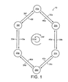
- the system 10 comprises six nodes 20a, 20b, 20c, 20d, 20e, 20f serially connected in a ring configuration by optical fibre waveguides 30a-30f, 40a-40f. It will be appreciated that the system 10 is an example of one configuration of communication system in which the invention can be implemented. The system 10 can be modified to include fewer or more nodes depending upon client requirements.
- the fibre waveguides 30a, 30b, 30c, 30d, 30e, 30f are coupled from the nodes 20a, 20b, 20c, 20d, 20e, 20f to the nodes 20b, 20c, 20d, 20e, 20f, 20a respectively to convey radiation components in a clockwise (CW) direction around the system 10.
- the fibre waveguides 40a, 40b, 40c, 40d, 40e, 40f are coupled from the nodes 20b, 20c, 20d, 20e, 20f, 20a to the nodes 20a, 20b, 20c, 20d, 20e, 20f respectively to convey radiation components in a counter clockwise (CCW) direction around the system 10.
- Communication traffic to be conveyed between the nodes 20 is modulated onto optical radiation having a free-space wavelength in the order of 1550 nm, the radiation being partitioned into 32 wavelength division multiplexed (WDM) radiation' components or bands.
- the bands are also known as channels.
- the channels are spaced apart in wavelength by 0.8 nm which corresponds to substantially a 100 GHz frequency spacing.
- Each channel is capable of conveying information asynchronously and independently of the other channels.
- the waveguides 30, 40 are each capable of simultaneously conveying the 32 channels in CW, CCW directions respectively in the system 10. It will also be appreciated that not all the channels are necessarily populated with modulated radiation components; channel population will depend upon how the system 10 is configured for its clients.
- the nodes 20 are substantially mutually similar in configuration.
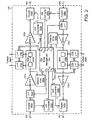
- the node 20a is shown included within a broken line 100.
- the node 20a comprises a node management unit 110, and first and second optical add-drop multiplexers (ADMs) 120a, 120b respectively.
- the node 20a further includes first, second, third and fourth erbium-doped fibre amplifiers (EDFA) 130a, 130b, 130c, 130d respectively.
- EDFA erbium-doped fibre amplifiers
- the node 20a also comprises first, second, third and fourth optical couplers 140a, 140b, 140c, 140d respectively.
- the node 20a incorporates first and second input optical attenuators 150a, 150b respectively and also first and second photodetector arrays 160a, 160b respectively.
- the first ADM 120a has associated therewith first and second optical attenuators 170a, 170b respectively, and the second ADM 120b has associated therewith third and fourth optical attenuators 170c, 170d.
- the node comprises optical-to-electrical (O/E) converters 180a, 180b and electrical-to-optical (E/O) converters 190a, 190b.
- the fibre waveguide 30f is coupled to an optical input port of the first coupler 140a.
- a first optical output port of the coupler 140a is coupled via the O/E converter 180a to an electrical input S 1in of the management unit 110; a second optical output port of the coupler 140a is coupled to an optical input port of the attenuator 150a.
- An optical output port of the attenuator 150a is connected via the first EDFA1 130a to an optical input port of the ADM 120a and also to an optical input port of the detector array 160a.
- the detector 160a includes optical diffraction components, for example one or more Bragg gratings, for spatially dispersing radiation components (channels) and detecting at photodiodes their individual power intensities for providing corresponding electrical output signals, digital representations, indicative of the power intensity of each associated WDM radiation component (WDM channel).
- the detector array 160a is connected to an electrical input port P 1 of the management unit 110 for conveying power intensity data to the management unit 110.
- the management unit 110 comprises an electrical output A 1 which is coupled to a control input of the input optical attenuator 150a for controlling optical attenuation therethrough.
- the ADM 120a includes two dielectric add-drop filters (not shown in Figure 2) which are each tuned to the wavelength band of an associated radiation component (channel).
- the filters are coupled in series and their input/output ports are presented at first and second optical ports of the ADM 120a.
- the first and second optical ports are coupled via the optical attenuators 170a, 170b respectively to clients (not shown), such connections often being termed tributary ports.
- An electrical control output B 1 of the management unit 110 is connected to control inputs of the first and second optical attenuators 170a, 170b for controlling optical attenuation through these attenuators.
- An optical output port of the ADM 120a is coupled via the second EDFA2 130b to a first optical input port of the second optical coupler 140b.
- a supervisory output S 1out is connected via the E/O converter 190a to a second optical input port of the second optical coupler 140b.
- An optical output port of the second optical coupler 140b is coupled to the fibre wave
- the fibre waveguide 40a is coupled to an optical input port of the third optical coupler 140c.
- a first optical output port of the optical coupler 140c is coupled via the O/E converter 180b to an electrical input S 2in of the management unit 110; a second optical output port of the optical coupler 140c is coupled to an optical input port of the optical attenuator 150b.
- An optical output port of the optical attenuator 150b is connected via the third EDFA3 130c to an optical input port of the ADM 120b and also to an input port of the detector array 160b.
- the detector array 160b includes optical diffraction components, for example one or more Bragg gratings, for spatially dispersing radiation components and detecting at photodiodes their individual power intensities for providing corresponding electrical output signals indicative of the power intensity of each associated WDM radiation component.
- the detector array 160b is connected to an electrical input port P 2 of the management unit 110 for conveying power intensity data to the unit 110.
- the unit 110 comprises an electrical output A 2 which is coupled to a control input of the optical attenuator 150b for controlling optical attenuation therethrough.
- the ADM 120b includes two dielectric add-drop filters (not shown in Figure 2) which are each tuned to the wavelength band of an associated radiation component.
- the filters are coupled in series and their input/output ports are presented at first and second optical ports of the ADM 120b.
- the first and second optical ports are coupled via the optical attenuators 170c, 170d respectively to clients.
- An electrical control output B 2 of the management unit 110 is connected to an electrical control inputs of the optical attenuators 170c, 170d for controlling optical attenuation through these attenuators.
- An optical output port of the ADM 120b is coupled via the fourth EDFA4 130d to a first optical input port of the fourth coupler 140d.
- a supervisory output S 2out is connected via the E/O converter 190b, to a second optical input port of the fourth optical coupler 140d.
- An optical output port of the fourth optical coupler 140d is coupled to the fibre waveguide 40f.
- node 20a within the system 10 will now be described, firstly for CW (clockwise) propagating radiation around the system 10 and then for CCW (counter clockwise) propagating radiation around the system 10.
- the other nodes 20b, 20c, 20d, 20e function in a similar manner.
- a first token is passed in a CW direction along the waveguides 30.
- a second token is passed in a CCW direction along the waveguides 40.
- the system 10 can be configured to use only a single token which is alternately passed in CW and CCW directions around the system 10.
- the management unit 110 includes a microcontroller with associated random access memory (RAM) and read only memory (ROM) for storing node operating software and data parameters received via a supervisory channel present in optical radiation received in one or more of the fibre waveguides 30f, 40a.
- Each node 20 in particular includes operating software capable of receiving and interpreting a token at the node 20.
- the token comprises an array of data which will be described in further detail later.
- each node 20 is also capable of writing data values into the token.
- WDM radiation components propagate along the waveguide 30f and are received at the optical coupler 140a.
- the radiation components correspond to one or more communication channels and also to a supervisory channel/s.
- the first optical coupler 140a is operable to separate the radiation component corresponding to the supervisory channel/s and divert it out to the first output port of the coupler 140a and operable to the other radiation components (communication channels) to the second output port of the coupler 140a.
- the supervisory channel radiation component is converted into a corresponding electrical signal by the O/E converter 180a which is passed to the S 1in input of the management unit 110.
- the aforementioned CW propagating token is thereby conveyed in the supervisory channel to the management unit 110.
- Radiation components other than the supervisory channel radiation component are output from the second port of the first coupler 140a via the first optical attenuator 150a to the first EDFA1 130a.
- the first EDFA1 130a optically amplifies the radiation components to provide corresponding amplified radiation which propagates to the ADM 120a and also to the detector array 160a.
- the array 160a spatially separates the radiation components and then measures the power intensity of each of the radiation components to generate corresponding electrical signals which are passed to the input P 1 of the management unit 110.
- Software executing in the management unit 110 interprets the CW propagating token and also the data provided at the input P 1 to regulate adjustment of the optical attenuation of the optical attenuators 150a, 170a, 170b.
- Radiation received at the ADM 120a propagates through the add-drop filters therein where radiation components of preferred channels are dropped for output via the optical attenuators 170a, 170b. Radiation components (wavelength channels) can also be added via these optical attenuators 170a, 170b on account of the reciprocal optical characteristics of the add-drop filters. Radiation propagating through the ADM 120a, and radiation components added, propagate to the second EDFA2 130b which amplifies radiation components and outputs corresponding amplified radiation to the first input port of the second optical coupler 140b.
- Supervisory channel data output from the S 1out output of the management unit 110 passes through the associated E/O converter 190a to provide a corresponding supervisory channel radiation component which propagates to the second input port of the second optical coupler 140b. Radiation components received at the first and second input ports of the second coupler 140b are combined and output from the coupler 140b for propagating along the fibre waveguide 30a further within the system 10.
- WDM radiation components propagate along the waveguide 40a and are received at the third optical coupler 140c.
- the radiation components correspond to one or more communication channels (wavelength channels) and also to a supervisory channel.
- the optical coupler 140c is operable to separate a radiation component corresponding to the supervisory channel and divert it out to the first output port of the coupler 140c and transmit other radiation components (communication channels) to the second output port of the coupler 140c.
- the supervisory channel radiation component propagates to the associated O/E converter 180b where it is converted into a corresponding electrical signal which is passed to the S 2in input of the management unit 110. The aforementioned token is thereby conveyed in the supervisory channel to the management unit 110.
- Radiation components other than the supervisory channel radiation component are output from the second port of the third coupler 140c via the second input optical attenuator 150b to the third EDFA3 130c.
- the third EDFA3 130c optically amplifies the radiation components to provide corresponding amplified radiation which propagates to the ADM 120b and also to the detector array 160b.
- the array 160b spatially separates the radiation components and then measures the power intensity of each of the radiation components to generate corresponding electrical signals which are passed to the input P 2 of the management unit 110.
- Software executing in the management unit 110 interprets the CCW propagating token and also the data provided at the input P 2 to regulate adjustment of the optical attenuation of the optical attenuators 150b, 170c, 170d.
- Radiation received at the ADM 120b propagates through the add-drop filters therein where radiation components of preferred channels are dropped for output via the optical attenuators 170c, 170d. Radiation components can also be added via these optical attenuators 170c, 170d on account of the reciprocal optical characteristics of the add-drop filters. Radiation propagating through the ADM 120b and radiation components added propagate to the fourth EDFA4 130d which amplifies radiation components and outputs corresponding amplified radiation to the first input port of the fourth coupler 140d.
- Supervisory channel data (including the control token) output from the S 2out output of the management unit 110 passes through the associated E/O converter 190b to provide a corresponding supervisory channel radiation component which propagates to the second input port of the fourth optical coupler 140d. Radiation components received at the first and second input ports of the fourth optical coupler 140d are combined and output from the coupler 140d for propagating along the fibre waveguide 40f.
- one or more of the EDFAs 130 can be omitted from the node 20a for reducing cost; such omission pertains also to the other nodes 20b, 20c, 20d, 20e, 20f of the system 10.
- the number of nodes 20 within the system can be varied depending upon client requirements.
- the EDFAs 130c can be configured when initially setting up the system 10 to provide either 16 dB gain or 24 dB gain.
- the system 10 is configured to have a diameter of 180 km and convey up to 32 active wavelength channels, it is beneficial that the system 10 so configured comprises in a range of ten to fifteen EDFAs, preferably thirteen EDFAs in total. Information relating to the number of EDFAs in the system 10 and their optical gains is conveyed in the token propagating within the system 10.
- Each of the tokens can be implemented in a number of different ways.
- One example of the token is illustrated in Figure 3 and indicated generally by 300.
- the token 300 comprises four data arrays: a channel power array 310; an optical amplifier gain array 320; a channel interconnectivity array 330; and an optical attenuator settings array 340.
- the channel power array 310 an entry is made for each node 20 for each WDM channel, there being allowance for data entry for n nodes in the token, relating to power measurement performed by the detector arrays 160a, 160b at each node 20.
- optical amplifier gain array 320 the optical gains of each of the EDFAs 130 in each of the n nodes 20 is recorded. Where EDFAs are not included within the nodes 20, an entry is made in the array 320 that no gain (0 dB) occurs. As elucidated in the foregoing, optical gains of the EDFAs 130 can be preferably set to either 16 dB or 24 dB, although other gain settings are possible.
- the channel interconnectivity array 330 data entry is made regarding routing of channels through the system, in other words the channel settings of dielectric filters included within the ADMs 120 in the nodes 20.
- the wavelength channels each define an interconnection between nodes.
- optical attenuator settings array 340 the attenuator 150, 170 settings (optical attenuation) employed at each of the nodes 20 is recorded.
- the channel power 310 and the optical attenuator settings 340 are updated as the token 300 is passed around the system 10.
- Each node 20 is only allowed to update locations within the arrays 310, 340 relating to the respective node; in other words node 20a updates values in the token relating to node 20a, and so on.
- the token 300 can be configured to convey parameters for both CW and CCW communication directions. Otherwise, the system 10 can employ two tokens, one passed CW around the system 10 and the other passed CCW around the system, the tokens being substantially independent.
- One of the nodes 20, for example the first node 20a, is designated as a principal node for initiating the token 300 propagation each time the system 10 is initially energized.
- Operating software residing in the management unit 110 of each node 20 is arranged to receive the token 300, to interpret the data in the arrays 310, 320, 330, 340 and calculate appropriate settings for the optical attenuators 150, 170.
- the operating software is configured to obtain a nominally levelled power for each channel at a mid-point in each connection route employing the channel; for example channel five conveying communication traffic from node 20a to node 20c via node 20b would be of nominally levelled power at node 20b, be of somewhat higher relative power at node 20a and somewhat lower relative poser at node 20c, there being attenuation in the order of 0.4 dB through each add-drop filter included within the nodes 20a, 20b, 20c through which the communication traffic bearing radiation component propagates; attenuation also arises within the optical couplers 140 for example.
- the operating software also takes into account that a sufficiently high radiation power for each radiation component is required in the system 10 for providing a target signal-to-noise ratio and hence a corresponding upper limit for bit error rate (BER) within the system 10.
- BER bit error rate
- the operating software in the node 20 calculates from the token 300 how it needs to set its optical attenuators 150, 170 to substantially level each channel; for example levelling can correspond to adjustment to within a range of +/- 30 % from nominal power. Moreover, the operating software also calculates from the token 300 settings for the optical attenuators 150, 170 to ensure that radiation components within the system 10 are of sufficient power to provide a target signal-to-noise, and hence BER performance; for example, to adjust the optical attenuators 150, 170 to ensure that radiation component power levels within the system 10 are at least 6 dB greater than minimum power levels needed to guarantee a given BER.
- the operating software addresses the calculation by solving a series of simultaneous equations using known matrix inversion techniques.
- the node 20 records its optical attenuator settings in the token 300 and then passes the token to its neighbouring node.
- Each of the nodes is not permitted to adjust its optical attenuators 150, 170 unless it is in possession of the token 300.
- each node 20 is allowed to possess the token 300 for a sufficient period to allow its optical attenuators 150, 170 to settle; the attenuators 150, 170 can, for example, be thermally-controlled optical attenuators.
- Settling is deemed to have occurred when the attenuators 150, 170 attain within 10 % of their final fully-settled optical attenuation value; more preferably, the attenuators 150, 170 should have settled to within 2 % of their final settled value for settling to be deemed to have occurred. If the token 300 is passed around the system 10 at a rate greater than the settling times of the attenuators 150, 170, it is necessary to pass the token 300 a plurality of times around the system 10 so that the system 10 iteratively adjusts itself.
- system 10 is provided as one example system embodying the invention.
- Other systems employing token-controlled regulation of system node settings are included within the scope of the invention.
- the method of regulating radiation component power using token according to the invention can be used for controlling system parameters in addition to optical attenuation, for example:
Landscapes
- Engineering & Computer Science (AREA)
- Computer Networks & Wireless Communication (AREA)
- Signal Processing (AREA)
- Optical Communication System (AREA)
- Small-Scale Networks (AREA)
- Control Of Electric Motors In General (AREA)
Claims (24)
- Verfahren zum Regulieren der Leistung eines Wellenlängenkanals in einem optischen, wellenlängengemultiplexten (WDM-) Kommunikationssystem (10), wobei das System eine Mehrzahl von Knoten (20) umfasst, die durch Wellenleiter (30, 40) miteinander verbunden sind, wobei die Knoten leistungsregulierende Einrichtungen (150) beinhalten, zum Regulieren der Leistung der WDM-Wellenlängenkanäle an dem Knoten, wobei das Verfahren
gekennzeichnet ist durch:an jedem Knoten (20), Messen der Leistung jedes WDM-Wellenlängenkanals (160), der an diesem empfangen wird; Aufzeichnen der Leistung (310) jedes der WDM-Wellenlängenkanäle in einem Token-Datenpaket (300); Übermitteln des Token-Datenpakets (300) durch das System hindurch von Knoten (20) zu Knoten (20); und, an jedem Knoten, welcher leistungsregulierende Einrichtungen (150) beinhaltet, Anpassen der leistungsregulierenden Einrichtungen (150, 170) in Reaktion auf den Empfang des Token-Datenpakets (300) und in Abhängigkeit von den WDM-Nellenlängenkanal-Leistungen an einem oder mehreren anderen Knoten sowie den Wellenlängenkanal-Leistungen an dem Knoten, um die Leistung der WDM-Wellenlängenkanäle an dem Knoten zu regulieren. - Verfahren nach Anspruch 1, bei welchem die leistungsregulierenden Einrichtungen ein optisches Dämpfungsglied (150, 170) mit variabler Dämpfung umfassen und das Verfahren das Anpassen der Dämpfung des optischen Dämpfungsglieds (150, 170) umfasst, um zumindest teilweise die Leistungen der WDM-Wellenlängenkanäle in dem System (10) auszugleichen.
- Verfahren nach Anspruch 2, und ferner umfassend, an jedem Knoten, der ein optisches Dämpfungsglied enthält, das Aufzeichnen der an dem Knoten angewandten Dämpfung (340) in dem Token-Datenpaket, zur nachfolgenden Übermittlung an einen oder mehrere andere Knoten (20) des Systems (10).
- Verfahren nach Anspruch 3, und ferner umfassend das Übermitteln von Kanalverbindungsdaten (330) in dem Token-Datenpaket, welche die Verbindung zwischen Knoten bezüglich der Wellenlängenkanäle definieren.
- Verfahren nach Anspruch 4, und ferner umfassend, in Reaktion auf den Empfang des Token-Datenpakets (300) und in Abhängigkeit von den Kanalverbindungsdaten (330), im Wesentlichen Ausgleichen der Leistung für jeden Wellenlängenkanal an einem Mittelpunkt in jeder Verbindungsroute, welche den Kanal verwendet.
- Verfahren nach einem der vorhergehenden Ansprüche, bei welchem einer oder mehrere der Knoten (20) einen optischen Verstärker (130) enthalten und welches umfasst, an jedem Knoten, der einen optischen Verstärker enthält, in dem Token-Datenpaket die Verstärkung (320) des Verstärkers aufzuzeichnen, zur nachfolgenden Übermittlung an einen oder mehrere andere Knoten (20) des Systems (10).
- Verfahren nach einem der vorhergehenden Ansprüche, bei welchem die Knoten (20) in einer Ringkonfiguration verbunden sind und welches umfasst, das Token-Datenpaket (300) um den Ring herum zu übermitteln.
- Verfahren nach Anspruch 7, und umfassend, das Token-Datenpaket (300) abwechselnd in Ührzeigerrichtung und entgegen der Uhrzeigerrichtung um den Ring herum zu übermitteln.
- Verfahren nach Anspruch 7, und umfassend, zumindest ein Token-Datenpaket (300) in Uhrzeigerrichtung um den Ring herum weiterzuleiten und gleichzeitig zumindest ein Token-Datenpaket (300) entgegen der Uhrzeigerrichtung um den Ring herum weiterzuleiten.
- Verfahren nach einem der vorhergehenden Ansprüche, und umfassend das Übermitteln des Token-Datenpakets (300) mit allgemeinem Kommunikationsverkehr.
- Verfahren nach einem der Ansprüche 1 bis 9, und umfassend das Übermitteln des Token-Datenpakets (300) um das System (10) herum in dem WDM-Überwachungskanal desselben.
- Verfahren nach einem der vorhergehenden Ansprüche, und umfassend das Festlegen eines der Knoten (20a) als Hauptknoten zum Auslösen des Übermittelns des Token-Datenpakets (300) um das System (10) herum nach einer anfänglichen Systemeinschaltung.
- Wellenlängengemultiplextes (WDM-), optisches Kommunikationssystem (10), welches eine Mehrzahl von Knoten (20) umfasst, die durch Wellenleiter (30, 40) miteinander verbunden sind, um zwischen den Knoten WDM-Wellenlängenkanäle zu übertragen, wobei die Knoten leistungsregulierende Einrichtungen (150, 170) zum regulieren der Leistung der WDM-Wellenlängenkanäle an dem Knoten umfassen, wobei das System
gekennzeichnet ist durch:Leistungsmesseinrichtungen (160) an jedem Knoten (20), zum Messen der Leistung jedes an diesem empfangenen WDM-Wellenlängenkanals; Aufzeichnungseinrichtungen zum Aufzeichnen der Leistung (310) jedes der WDM-Wellenlängenkanäle in einem Token-Datenpaket (300); Einrichtungen zum Übermitteln des Token-Datenpakets (300) durch das System hindurch von Knoten (20) zu Knoten (20); und, an jedem Knoten, welcher leistungsregulierende Einrichtungen (150) beinhaltet, eine Steuereinrichtung (110), die dazu dient, die leistungsregulierenden Einrichtungen (150, 170) in Reaktion auf den Empfang des Token-Datenpakets (300) und in Abhängigkeit von den WDM-Wellenlängenkanal-Leistungen an einem oder mehreren anderen Knoten sowie den Wellenlängenkanal-Leistungen an dem Knoten anzupassen, um die Leistung der WDM-Wellenlengenkanäle an dem Knoten zu regulieren. - Kommunikationssystem nach Anspruch 13,
bei welchem die leistungsregulierenden Einrichtungen (150, 170) ein optisches Dämpfungsglieds mit variabler Dämpfung umfassen und die Steuereinrichtung (110) dazu dient, die Dämpfung des optischen Dämpfungsglieds (150, 170) anzupassen, um zumindest teilweise die Leistungen der WDM-Wellenlängenkanäle in dem System (10) auszugleichen. - Kommunikationssystem nach Anspruch 14,
bei welchem an jedem Knoten, der ein optisches Dämpfungsglied (150, 170) enthält, die Aufzeichnungseinrichtung ferner dazu dient, in dem Token-Datenpaket die an dem Knoten angewandte Dämpfung (340) aufzuzeichnen, und zwar zur nachfolgenden Übermittlung an einen oder mehrere andere Knoten (20) des Systems (10). - Kommunikationssystem nach Anspruch 15,
und ferner umfassend das Übermitteln von Kanalverbindungsdaten (330), welche die Verbindung zwischen Knoten bezüglich der Wellenlängenkanäle definieren, in dem Token-Datenpaket. - Kommunikationssystem nach Anspruch 16,
bei welchem die Steuereinrichtung dazu dient, in Reaktion auf den Empfang des Token-Datenpakets (300) und in Abhängigkeit von den Kanalverbindungsdaten (330) die Leistung für jeden Wellenlängenkanal an einem Mittelpunkt in jeder Verbindungsroute, welche den Kanal verwendet, im Wesentlichen auszugleichen. - Kommunikationssystem nach einem der Ansprüche 13 bis 17, bei welchem einer oder mehrere der Knoten (20) einen optischen Verstärker (130) enthalten und bei welchem an jedem Knoten, der einen optischen Verstärker enthält, die Aufzeichnürigseinrichtung dazu dient, in dem Token-Datenpaket die Verstärkung (320) des Verstärkers aufzuzeichnen, und zwar zur nachfolgenden Übermittlung an einen oder mehrere andere Knoten (20) des Systems (10).
- Kommunikationssystem nach einem der Ansprüche 13 bis 17, bei welchem die Knoten (20) in einer Ringkonfiguration verbunden sind und die Einrichtung zum übermitteln des Token-Datenpakets (300) dazu dient, das Token-Datenpaket (300) um den Ring herum zu übermitteln.
- Kommunikationssystem nach Anspruch 19,
bei welchem die Einrichtung zum Übermitteln des Token-Datenpakets (300) dazu dient, das Token-Datenpaket (300) abwechselnd in Uhrzeigerrichtung und entgegen der Uhrzeigerrichtung um den Ring herum zu übermitteln. - Kommunikationssystem nach Anspruch 19,
bei welchem die Einrichtung zum Übermitteln des Token-Datenpakets (300) dazu dient, zumindest ein Token-Datenpaket (300) in Uhrzeigerrichtung um den Ring herum weiterzuleiten und gleichzeitig zumindest ein Token-Datenpaket (300) entgegen der Uhrzeigerrichtung um den Ring herum weiterzuleiten. - Kommunikationssystem nach einem der Ansprüche 13 bis 21, bei welchem die Einrichtung zum Übermitteln des Token-Datenpakets (300) dazu dient, das Token-Datenpaket (300) mit allgemeinem Kommunikationsverkehr zu übermitteln.
- Kommunikationssystem nach einem der Ansprüche 13 bis 21, bei welchem die Einrichtung zum Übermitteln des Token-Datenpakets (300) dazu dient, das Token-Datenpaket (300) um das System (10) herum in dem WDM-Überwavhungskanal desselben zu übermitteln.
- Kommunikationssystem nach einem der Ansprüche 13 bis 23, bei welchem einer der Knoten (20a) einen Hauptknoten darstellt und dazu dient, das Übermitteln des Token-Datenpakets (300) um das System (10) herum nach einer anfänglichen Systemeinschaltung auszulösen.
Applications Claiming Priority (3)
| Application Number | Priority Date | Filing Date | Title |
|---|---|---|---|
| GB0103980 | 2001-02-17 | ||
| GB0103980A GB2372388A (en) | 2001-02-17 | 2001-02-17 | Using token passing to control power in a WDM communication system |
| PCT/GB2002/000612 WO2002067480A1 (en) | 2001-02-17 | 2002-02-12 | Regulating radiation component power in wavelength division multiplexed optical communication systems |
Publications (2)
| Publication Number | Publication Date |
|---|---|
| EP1362443A1 EP1362443A1 (de) | 2003-11-19 |
| EP1362443B1 true EP1362443B1 (de) | 2007-04-11 |
Family
ID=9908990
Family Applications (1)
| Application Number | Title | Priority Date | Filing Date |
|---|---|---|---|
| EP02712057A Expired - Lifetime EP1362443B1 (de) | 2001-02-17 | 2002-02-12 | Komponentenweise regelung der stralungsleistung in optischen wellenlängenmultiplex-nachrichtenübertragungssystemen |
Country Status (9)
| Country | Link |
|---|---|
| US (1) | US7447432B2 (de) |
| EP (1) | EP1362443B1 (de) |
| JP (1) | JP4344520B2 (de) |
| CN (1) | CN100429879C (de) |
| AT (1) | ATE359629T1 (de) |
| CA (1) | CA2438332C (de) |
| DE (1) | DE60219434T2 (de) |
| GB (1) | GB2372388A (de) |
| WO (1) | WO2002067480A1 (de) |
Families Citing this family (7)
| Publication number | Priority date | Publication date | Assignee | Title |
|---|---|---|---|---|
| US7231148B2 (en) * | 2002-03-28 | 2007-06-12 | Fujitsu Limited | Flexible open ring optical network and method |
| EP1641148B1 (de) * | 2004-09-24 | 2007-10-31 | Infineon Technologies AG | Verfahren zur Optimierung der Lichtleistung in einem optischen Netzwerk und optisches Netzwerk |
| US7809276B2 (en) * | 2004-11-30 | 2010-10-05 | Finisar Corporation | Inter-transceiver module communication for optimization of link between transceivers |
| US8520579B2 (en) * | 2005-12-22 | 2013-08-27 | Telefonaktiebolaget L M Ericsson (Publ) | Token based radio resource management |
| CN101656577B (zh) * | 2009-09-16 | 2012-03-28 | 中兴通讯股份有限公司 | 光网络系统的自动功率调整系统及方法 |
| US8340515B2 (en) * | 2009-11-03 | 2012-12-25 | Fujitsu Limited | Method and system for monitoring optical dispersion in an optical signal |
| US8594317B2 (en) * | 2009-12-31 | 2013-11-26 | Bce Inc. | Method, communication device and computer-readable media for conveying an audio stream to a user of a communication device during an outgoing call |
Citations (2)
| Publication number | Priority date | Publication date | Assignee | Title |
|---|---|---|---|---|
| WO1999021302A1 (en) * | 1997-10-21 | 1999-04-29 | Telefonaktiebolaget Lm Ericsson (Publ) | Optical amplifier control |
| EP0936760A2 (de) * | 1998-02-16 | 1999-08-18 | Hitachi, Ltd. | Optisches Übertragungssystem und Verfahren zur seiner Überwachung |
Family Cites Families (6)
| Publication number | Priority date | Publication date | Assignee | Title |
|---|---|---|---|---|
| US6452701B1 (en) * | 1997-03-19 | 2002-09-17 | Fujitsu Limited | Wavelength division multiplexing communications network supervisory system |
| SE9702685D0 (sv) * | 1997-07-11 | 1997-07-11 | Ericsson Telefon Ab L M | Self-healing ring network and a method for fault detection and rectifying |
| JP3551407B2 (ja) * | 1998-02-16 | 2004-08-04 | 富士通株式会社 | 波長多重光伝送システム |
| US6243175B1 (en) * | 1998-08-06 | 2001-06-05 | Ciena Corporation | WDM optical communication system having reduced loss and cross-talk |
| US6304347B1 (en) * | 1999-09-03 | 2001-10-16 | Oni Systems Corporation | Optical power management in an optical network |
| US6922532B2 (en) * | 2000-12-07 | 2005-07-26 | Frederic Simard | Optical performance monitoring for D/WDM networks |
-
2001
- 2001-02-17 GB GB0103980A patent/GB2372388A/en not_active Withdrawn
-
2002
- 2002-02-12 AT AT02712057T patent/ATE359629T1/de not_active IP Right Cessation
- 2002-02-12 EP EP02712057A patent/EP1362443B1/de not_active Expired - Lifetime
- 2002-02-12 WO PCT/GB2002/000612 patent/WO2002067480A1/en not_active Ceased
- 2002-02-12 CN CNB028084551A patent/CN100429879C/zh not_active Expired - Fee Related
- 2002-02-12 JP JP2002566886A patent/JP4344520B2/ja not_active Expired - Fee Related
- 2002-02-12 DE DE60219434T patent/DE60219434T2/de not_active Expired - Lifetime
- 2002-02-12 US US10/468,163 patent/US7447432B2/en not_active Expired - Fee Related
- 2002-02-12 CA CA2438332A patent/CA2438332C/en not_active Expired - Fee Related
Patent Citations (2)
| Publication number | Priority date | Publication date | Assignee | Title |
|---|---|---|---|---|
| WO1999021302A1 (en) * | 1997-10-21 | 1999-04-29 | Telefonaktiebolaget Lm Ericsson (Publ) | Optical amplifier control |
| EP0936760A2 (de) * | 1998-02-16 | 1999-08-18 | Hitachi, Ltd. | Optisches Übertragungssystem und Verfahren zur seiner Überwachung |
Also Published As
| Publication number | Publication date |
|---|---|
| EP1362443A1 (de) | 2003-11-19 |
| GB0103980D0 (en) | 2001-04-04 |
| JP4344520B2 (ja) | 2009-10-14 |
| CA2438332C (en) | 2012-05-01 |
| DE60219434T2 (de) | 2008-01-03 |
| US7447432B2 (en) | 2008-11-04 |
| DE60219434D1 (de) | 2007-05-24 |
| ATE359629T1 (de) | 2007-05-15 |
| WO2002067480A1 (en) | 2002-08-29 |
| US20040114927A1 (en) | 2004-06-17 |
| CA2438332A1 (en) | 2002-08-29 |
| CN1650557A (zh) | 2005-08-03 |
| CN100429879C (zh) | 2008-10-29 |
| JP2004527942A (ja) | 2004-09-09 |
| GB2372388A (en) | 2002-08-21 |
Similar Documents
| Publication | Publication Date | Title |
|---|---|---|
| EP1183798B1 (de) | Verfahren und vorrichtung zur optischen übertagungssteuerung mit kompensationskanalen | |
| US7339725B2 (en) | Optical transmission systems including optical amplifiers and methods of use therein | |
| EP1362443B1 (de) | Komponentenweise regelung der stralungsleistung in optischen wellenlängenmultiplex-nachrichtenübertragungssystemen | |
| US6714739B1 (en) | Optical transmission systems and optical receivers and receiving methods for use therein | |
| JP7056189B2 (ja) | ファイバー・ブラッグ格子移相器を用いた光位相感応増幅器 | |
| JPH11275020A (ja) | 波長多重光伝送システム及び波長多重光伝送システムに使用される光デバイス用損失差補償器の設計方法並びに波長多重光伝送システムの構築方法 | |
| JP7206922B2 (ja) | 位相感応型光増幅器のための位相シフタ | |
| US6147785A (en) | Coherent crosstalk attenuation apparatus | |
| CN101015153A (zh) | 波分复用(wdm)光解复用器 | |
| AU2001276858B2 (en) | Optical transmission systems including optical amplifiers and methods of use therein | |
| Boroditsky et al. | Power management for enhanced system performance of passive optical rings | |
| JP2025020627A (ja) | 光送信器、これを用いた光トランシーバ、及び波長制御方法 | |
| AU2001276858A1 (en) | Optical transmission systems including optical amplifiers and methods of use therein | |
| HK1057427B (en) | Optical transmission systems including optical amplifiers and methods of use therein |
Legal Events
| Date | Code | Title | Description |
|---|---|---|---|
| PUAI | Public reference made under article 153(3) epc to a published international application that has entered the european phase |
Free format text: ORIGINAL CODE: 0009012 |
|
| 17P | Request for examination filed |
Effective date: 20030916 |
|
| AK | Designated contracting states |
Kind code of ref document: A1 Designated state(s): AT BE CH CY DE DK ES FI FR GB GR IE IT LI LU MC NL PT SE TR |
|
| AX | Request for extension of the european patent |
Extension state: AL LT LV MK RO SI |
|
| 17Q | First examination report despatched |
Effective date: 20040105 |
|
| GRAP | Despatch of communication of intention to grant a patent |
Free format text: ORIGINAL CODE: EPIDOSNIGR1 |
|
| GRAS | Grant fee paid |
Free format text: ORIGINAL CODE: EPIDOSNIGR3 |
|
| RAP1 | Party data changed (applicant data changed or rights of an application transferred) |
Owner name: M(DGP1) LTD |
|
| RAP1 | Party data changed (applicant data changed or rights of an application transferred) |
Owner name: ERICSSON AB |
|
| RAP1 | Party data changed (applicant data changed or rights of an application transferred) |
Owner name: ERICSSON AB |
|
| 18D | Application deemed to be withdrawn |
Effective date: 20060909 |
|
| GRAL | Information related to payment of fee for publishing/printing deleted |
Free format text: ORIGINAL CODE: EPIDOSDIGR3 |
|
| GRAS | Grant fee paid |
Free format text: ORIGINAL CODE: EPIDOSNIGR3 |
|
| GRAA | (expected) grant |
Free format text: ORIGINAL CODE: 0009210 |
|
| AK | Designated contracting states |
Kind code of ref document: B1 Designated state(s): AT BE CH CY DE DK ES FI FR GB GR IE IT LI LU MC NL PT SE TR |
|
| PG25 | Lapsed in a contracting state [announced via postgrant information from national office to epo] |
Ref country code: LI Free format text: LAPSE BECAUSE OF FAILURE TO SUBMIT A TRANSLATION OF THE DESCRIPTION OR TO PAY THE FEE WITHIN THE PRESCRIBED TIME-LIMIT Effective date: 20070411 Ref country code: FI Free format text: LAPSE BECAUSE OF FAILURE TO SUBMIT A TRANSLATION OF THE DESCRIPTION OR TO PAY THE FEE WITHIN THE PRESCRIBED TIME-LIMIT Effective date: 20070411 Ref country code: CH Free format text: LAPSE BECAUSE OF FAILURE TO SUBMIT A TRANSLATION OF THE DESCRIPTION OR TO PAY THE FEE WITHIN THE PRESCRIBED TIME-LIMIT Effective date: 20070411 |
|
| REG | Reference to a national code |
Ref country code: CH Ref legal event code: EP |
|
| REG | Reference to a national code |
Ref country code: IE Ref legal event code: FG4D |
|
| REF | Corresponds to: |
Ref document number: 60219434 Country of ref document: DE Date of ref document: 20070524 Kind code of ref document: P |
|
| PG25 | Lapsed in a contracting state [announced via postgrant information from national office to epo] |
Ref country code: SE Free format text: LAPSE BECAUSE OF FAILURE TO SUBMIT A TRANSLATION OF THE DESCRIPTION OR TO PAY THE FEE WITHIN THE PRESCRIBED TIME-LIMIT Effective date: 20070711 |
|
| PG25 | Lapsed in a contracting state [announced via postgrant information from national office to epo] |
Ref country code: ES Free format text: LAPSE BECAUSE OF FAILURE TO SUBMIT A TRANSLATION OF THE DESCRIPTION OR TO PAY THE FEE WITHIN THE PRESCRIBED TIME-LIMIT Effective date: 20070722 |
|
| PG25 | Lapsed in a contracting state [announced via postgrant information from national office to epo] |
Ref country code: PT Free format text: LAPSE BECAUSE OF FAILURE TO SUBMIT A TRANSLATION OF THE DESCRIPTION OR TO PAY THE FEE WITHIN THE PRESCRIBED TIME-LIMIT Effective date: 20070911 |
|
| ET | Fr: translation filed | ||
| NLV1 | Nl: lapsed or annulled due to failure to fulfill the requirements of art. 29p and 29m of the patents act | ||
| REG | Reference to a national code |
Ref country code: CH Ref legal event code: PL |
|
| PG25 | Lapsed in a contracting state [announced via postgrant information from national office to epo] |
Ref country code: AT Free format text: LAPSE BECAUSE OF FAILURE TO SUBMIT A TRANSLATION OF THE DESCRIPTION OR TO PAY THE FEE WITHIN THE PRESCRIBED TIME-LIMIT Effective date: 20070411 |
|
| PG25 | Lapsed in a contracting state [announced via postgrant information from national office to epo] |
Ref country code: BE Free format text: LAPSE BECAUSE OF FAILURE TO SUBMIT A TRANSLATION OF THE DESCRIPTION OR TO PAY THE FEE WITHIN THE PRESCRIBED TIME-LIMIT Effective date: 20070411 |
|
| PG25 | Lapsed in a contracting state [announced via postgrant information from national office to epo] |
Ref country code: DK Free format text: LAPSE BECAUSE OF FAILURE TO SUBMIT A TRANSLATION OF THE DESCRIPTION OR TO PAY THE FEE WITHIN THE PRESCRIBED TIME-LIMIT Effective date: 20070411 Ref country code: NL Free format text: LAPSE BECAUSE OF FAILURE TO SUBMIT A TRANSLATION OF THE DESCRIPTION OR TO PAY THE FEE WITHIN THE PRESCRIBED TIME-LIMIT Effective date: 20070411 |
|
| PLBE | No opposition filed within time limit |
Free format text: ORIGINAL CODE: 0009261 |
|
| STAA | Information on the status of an ep patent application or granted ep patent |
Free format text: STATUS: NO OPPOSITION FILED WITHIN TIME LIMIT |
|
| 26N | No opposition filed |
Effective date: 20080114 |
|
| PG25 | Lapsed in a contracting state [announced via postgrant information from national office to epo] |
Ref country code: GR Free format text: LAPSE BECAUSE OF FAILURE TO SUBMIT A TRANSLATION OF THE DESCRIPTION OR TO PAY THE FEE WITHIN THE PRESCRIBED TIME-LIMIT Effective date: 20070712 |
|
| PGFP | Annual fee paid to national office [announced via postgrant information from national office to epo] |
Ref country code: IT Payment date: 20080226 Year of fee payment: 7 |
|
| PG25 | Lapsed in a contracting state [announced via postgrant information from national office to epo] |
Ref country code: MC Free format text: LAPSE BECAUSE OF NON-PAYMENT OF DUE FEES Effective date: 20080228 |
|
| PG25 | Lapsed in a contracting state [announced via postgrant information from national office to epo] |
Ref country code: IE Free format text: LAPSE BECAUSE OF NON-PAYMENT OF DUE FEES Effective date: 20080212 |
|
| PG25 | Lapsed in a contracting state [announced via postgrant information from national office to epo] |
Ref country code: CY Free format text: LAPSE BECAUSE OF FAILURE TO SUBMIT A TRANSLATION OF THE DESCRIPTION OR TO PAY THE FEE WITHIN THE PRESCRIBED TIME-LIMIT Effective date: 20070411 |
|
| PG25 | Lapsed in a contracting state [announced via postgrant information from national office to epo] |
Ref country code: LU Free format text: LAPSE BECAUSE OF NON-PAYMENT OF DUE FEES Effective date: 20080212 |
|
| PG25 | Lapsed in a contracting state [announced via postgrant information from national office to epo] |
Ref country code: TR Free format text: LAPSE BECAUSE OF FAILURE TO SUBMIT A TRANSLATION OF THE DESCRIPTION OR TO PAY THE FEE WITHIN THE PRESCRIBED TIME-LIMIT Effective date: 20070411 |
|
| PG25 | Lapsed in a contracting state [announced via postgrant information from national office to epo] |
Ref country code: IT Free format text: LAPSE BECAUSE OF NON-PAYMENT OF DUE FEES Effective date: 20090212 |
|
| REG | Reference to a national code |
Ref country code: FR Ref legal event code: PLFP Year of fee payment: 14 |
|
| PGFP | Annual fee paid to national office [announced via postgrant information from national office to epo] |
Ref country code: DE Payment date: 20150226 Year of fee payment: 14 |
|
| PGFP | Annual fee paid to national office [announced via postgrant information from national office to epo] |
Ref country code: GB Payment date: 20150226 Year of fee payment: 14 Ref country code: FR Payment date: 20150217 Year of fee payment: 14 |
|
| REG | Reference to a national code |
Ref country code: DE Ref legal event code: R119 Ref document number: 60219434 Country of ref document: DE |
|
| GBPC | Gb: european patent ceased through non-payment of renewal fee |
Effective date: 20160212 |
|
| REG | Reference to a national code |
Ref country code: FR Ref legal event code: ST Effective date: 20161028 |
|
| PG25 | Lapsed in a contracting state [announced via postgrant information from national office to epo] |
Ref country code: DE Free format text: LAPSE BECAUSE OF NON-PAYMENT OF DUE FEES Effective date: 20160901 Ref country code: FR Free format text: LAPSE BECAUSE OF NON-PAYMENT OF DUE FEES Effective date: 20160229 Ref country code: GB Free format text: LAPSE BECAUSE OF NON-PAYMENT OF DUE FEES Effective date: 20160212 |