EP1362279B1 - Rechnersystem mit mehreren versorgungseingängen - Google Patents
Rechnersystem mit mehreren versorgungseingängen Download PDFInfo
- Publication number
- EP1362279B1 EP1362279B1 EP01977887A EP01977887A EP1362279B1 EP 1362279 B1 EP1362279 B1 EP 1362279B1 EP 01977887 A EP01977887 A EP 01977887A EP 01977887 A EP01977887 A EP 01977887A EP 1362279 B1 EP1362279 B1 EP 1362279B1
- Authority
- EP
- European Patent Office
- Prior art keywords
- power
- unfiltered
- chassis
- filter
- power input
- Prior art date
- Legal status (The legal status is an assumption and is not a legal conclusion. Google has not performed a legal analysis and makes no representation as to the accuracy of the status listed.)
- Expired - Lifetime
Links
Images



Classifications
-
- G—PHYSICS
- G06—COMPUTING OR CALCULATING; COUNTING
- G06F—ELECTRIC DIGITAL DATA PROCESSING
- G06F1/00—Details not covered by groups G06F3/00 - G06F13/00 and G06F21/00
- G06F1/16—Constructional details or arrangements
- G06F1/18—Packaging or power distribution
- G06F1/189—Power distribution
Definitions
- the invention relates generally to computer systems with FRU's (field replaceable units), and the ability to supply power to a computer system selectively through the front or the back of the chassis of the computer system.
- FRU's field replaceable units
- Computer networks typically comprise a plurality of personal computers, or workstations, or network appliances and other data processing devices connected together for information exchange.
- network servers At the heart of the computer network is one or more network servers, hereafter generally referred to as “servers.”
- network servers are responsible for managing the network, running applications, and administering documents or data generated at the attached data processing devices.
- Network servers typically include one or more AC or DC power supplies, which serve the purpose of keeping the system up and running. Externally generated power which is provided to the server may have unacceptably wide variations in voltage and/or current. As a result, network servers typically filter power before supplying the power to sensitive components in the server.
- the network server typically has mass storage capabilities.
- the mass storage capabilities may be implemented by a disk subsystem or disk array where one or more disk drives are combined.
- SCSI is one example of an interface standard that permits multiple hard disk drives to be daisy chained to a single interface connector.
- One or more network servers are typically found in the data center for Internet Service Providers (ISPs) and Application Service Providers (ASPs).
- ISPs Internet Service Providers
- ASPs Application Service Providers
- One issue at sites supporting network servers is that space is often at a premium, and the servers are often rack mounted and closely co-located.
- An additional issue is found in the need for network servers to be scalable, given the disparate size and growth rates of ISPs and ASPs.
- NEBS Network Equipment Building Standards
- ETSI European Telecommunications Standards Institute
- One difference between American and European telco requirements is the power cabling of servers.
- American telco servers traditionally receive power from the rear of the server, and European telco servers traditionally receive power from the front of the server.
- a particular service provider's needs might be unique, or change over time.
- a power cable external to the chassis can run from the side of the server with a power inlet to the side of the server with access to external power.
- This approach has multiple disadvantages. An extra cable outside of the chassis adds yet another point of failure to the server, potentially decreasing the amount of uptime server availability. In the event that the cable fails, replacing the cable could be quite difficult if the server's power inlet is positioned on an inaccessible side of a server, requiring the entire server to be physically moved - just to replace the cable.
- the present invention discloses an apparatus for selectively supplying unfiltered power through one or more of multiple unfiltered power inputs to a power filter supported in a computer chassis. Allowing for multiple power inputs - on the power filter itself and on two or more surfaces of the computer chassis - adds great flexibility in where power cables external to the computer chassis may be located.
- a feature is a power filter having multiple inputs for unfiltered power.
- the power filter may also include a power output for filtered power which has blind-mating capacity.
- the blind-mating capacity allows another component such as a backplane to easily be connected with the power filter.
- Method embodiments allow selectable routing of power through one of multiple surfaces on the computer chassis, adapting a power filter in a computer with multiple power elements. While the description is in terms of the best mode for achieving one or more objectives, it will be appreciated by those skilled in the art that variations may be accomplished in view of those teachings without deviating from the scope of the invention as claimed.
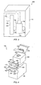
- FIG. 1 shows one example of an embodiment of a computer system, or server.
- the network server is the Netra ct1600 by Sun Microsystems, Inc.
- This embodiment shows a computer system 100 including a chassis 110 supporting a processor 120 and a power filter 130.
- the processor 120 and/or the power filter 130 may be physically supported directly by the chassis 110, or indirectly, for example through a backplane.
- a backplane may be a midplane.
- a power filter receives power generated externally from the server, and filters out unacceptable variations before supplying the power to the rest of the server.
- the power filter 130 includes a filter housing 140, a first power input 150, a second power input 160, and a power output 170.
- the power filter 130 receives unfiltered power from one or both of the first power input 150 and the second power input 160. After the power has been filtered by the power filter 130, filtered power enters the rest of the computer system 100 through a filtered power output 170.
- Various embodiments of the computer system 100 and the power filter 130 handle AC power and/or DC power.
- FIG. 2 shows another example of a computer system embodiment.
- a computer system 200 further includes a backplane 280 supported by the chassis 110 and supporting the processor 120.
- the backplane 280 receives power from the power filter 130 through the power output 170.
- the power output 170 can include blind-mating technology, permitting the backplane 280 to blind-mate with the power output 170.
- the power filter 130 receives unfiltered power from the first power input 150 and a second power input 260.
- the second power input 260 protrudes out of an aperture on a rear surface of the chassis 110. If not in use, the protruding second power input 260 may be covered to protect the computer system 200 and anyone servicing the computer system 200.
- An alternative embodiment does not have a protruding connector, but instead a cable coupling the second power input 260 to the rear surface of the chassis 110.
- FIG. 3 shows a further example of a computer system embodiment.
- a computer system 300 further includes a power cable 310 coupling the first power input 150 to an aperture on a front surface of the chassis 110. If the computer system 300 is not receiving power through the front surface of the chassis 110, the power cable 310 may not be included, and the first power input 150 may be covered to protect the computer system 300 and anyone servicing the computer system 300.
- the first power input 150 can be angled away from the rear surface of the chassis and/or toward the front surface of the chassis to ease a connection of the power cable 310 with the first power input 150.
- the power cable 310 can be included even if the computer system is receiving power through another power input and/or another surface, such as through a rear surface of the chassis 110 and the second power input 160. If a telco provider's requirements change, then power cabling external to the chassis can be rapidly modified, and the computer system can readily accept power through another surface of the chassis 110.
- the power filter 130 includes a single input, and the power filter 130 can selectably be coupled to receive power through the aperture on the front surface of the chassis 110 or through the aperture on the rear surface of the chassis 110.
- other surfaces of the chassis 110 define one or more apertures through which the computer receives unfiltered power, for example a side surface, a top surface, and/or a bottom surface.
- FIG. 4 shows an exploded diagram of multiple parts of an embodiment of the power filter 130.
- the power filter 130 may handle AC and/or DC power.
- the filter housing 140 includes includes a housing cover 410.
- the housing cover 410 can be part of the filter housing 140 or a separate part.
- the first power input 150 may be positioned on any surface of the filter housing 140, and in this embodiment is shown positioned on the housing cover 410.
- the filter housing 140 and the housing cover 410 support a filter 420.
- the filter 420 includes a first filter input 430 and a second filter input, not shown, on a rear surface of the filter 420. The positioning, shape, and configuration of the first filter input 430 and the second filter input is flexible.
- the filter 420 includes a single input adapted to receive power through one or more of multiple inputs external to the filter 420.
- Filter outputs 440 and 445 output, for example, positive and negative 48 volts DC.
- Another embodiment of the filter 420 may support AC voltage, for example anywhere from 90 V to 240 V. Various other positioning, shape, number, and voltages for the filter outputs are possible.
- the filter outputs 440 and 445 are coupled to the power output 170.
- the power output 170 receives power from the filter outputs 440 and 445, and acts as a connector to another component within the chassis 110, such as the backplane 280.
- the power output 170 can include blind-mating features such as blindmating connector 460, for example to simplify coupling of the backplane 280 to the power output 170.
- the power output 170 may be accompanied by projections 458 and/or 462 that can help position the blind-mating connector 460 of the power output 170 relative to the filter housing 140.
- the blind-mating connector 460 and the projections 458 and 462 of the power output 170 extend through apertures 452, 454, and 456 defined by a plate 450.
- the plate 450 may be separate part or integral with the filter housing 140.
- the power filter position the power inputs and the power output such that the power inputs are positioned on the same surface, and/or the power output is positioned on the same surface as at least one of the power inputs.
- FIG. 5 shows a top view of the power filter 130.
- a second filter input 510 is visible.
- FIG. 6 show a cross-sectional view of the power filter 130, as viewed across a cross-section line 520 in FIG. 5.
- conductive protrusions 610 and an internal cable 620 are visible.
- the internal cable 620 connects outputs of the filter 420 to the blind-mating connector 460 of the power output 170.
- FIG. 7 shows a side view of the power filter 130.
- FIG. 8 shows a side view of the housing cover 410 showing a side view of the conductive protrusion 610 and the first power input 150.
- FIG. 9 shows a perspective view of the housing cover 410 and the conductive protrusion 610 positioned on each side of the housing cover 410. The positioning, shape, and number of the conductive protrusions 610 may be adjusted in other embodiments.
- FIG. 10 shows an exemplary power cable 310.
- the power cable 310 helps route unfiltered power from an aperture on the chassis 110 to the power filter 130.
- the power cable 310 includes a first end 1010, a main cable 1030, and a second end 1050.
- the main cable 1030 has a plurality of power conductors. These power conductors have a first end 1020 and a second end 1040.
- the first end 1010 of the power cable 310 includes conducting protrusions 1060 and 1070.
- the conducting protrusions 1060 and 1070 of the power cable 310 come into conductive contact with the conductive protrusions 610 of the power filter 130, performing a grounding function.
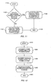
- FIG. 11, FIG. 12, FIG. 13 show exemplary flow diagrams of some possible methods. Elements of the flow diagrams may be removed, rearranged, added to, and/or modified.
- the flow diagram of FIG. 11 illustrates an exemplary method for selectably routing power through a front surface or a rear surface of a computer chassis.
- a decision is made whether unfiltered power should be routed through the front surface of the computer chassis or the rear surface of the computer chassis.
- Unfiltered power refers to power which has not been filtered by a power filter within the computer chassis.
- unfiltered power is routed through the rear surface of the chassis and then to the power filter within the chassis.
- the power filter may handle AC and/or DC power.
- power is routed through the front surface of the computer chassis and then to the power filter within the chassis.
- the method ends at 1150.
- Other embodiments may route power through other surfaces, such as a top surface, a side surface, an/or a bottom surface.
- FIG. 12 illustrates an exemplary method for adapting a power filter. After start 1210, in 1220 a first power input is connected to the power filter. In 1230, a second power input is connected to the power filter. After 1240 where the power filter is positioned in the computer chassis, the method ends at 1250.
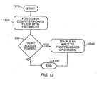
- FIG. 13 illustrates an exemplary method for selectively configuring a computer for receiving front access power.
- a power filter having a first input for unfiltered power and a second input for unfiltered power is positioned within a computer chassis.
- a decision is made whether front access power is desired.
- front access power is desired, at least one of the unfiltered power inputs is coupled to the front surface of the chassis. The method ends at 1350.
Landscapes
- Engineering & Computer Science (AREA)
- Power Engineering (AREA)
- Theoretical Computer Science (AREA)
- Human Computer Interaction (AREA)
- Physics & Mathematics (AREA)
- General Engineering & Computer Science (AREA)
- General Physics & Mathematics (AREA)
- Power Sources (AREA)
- Hardware Redundancy (AREA)
- Networks Using Active Elements (AREA)
Claims (40)
- Computersystem (100) mit:einem Gehäuse (110), das eine erste Öffnung und eine zweite Öffnung hat, wobei die erste Öffnung sich auf einer ersten Oberfläche des Gehäuses befindet und die zweite Öffnung sich auf einer zweiten Oberfläche des Gehäuses befindet,einen Prozessor (120), der in dem Gehäuse gehaltert ist,einen Stromfilter (130), der in dem Gehäuse gehaltert ist,einen ersten, ungefilterten Stromeingang (150), der dafür ausgelegt ist, Strom durch die erste Öffnung des Gehäuses zu empfangen und der in dem Gestell mit dem Stromfilter verbunden ist,einen zweiten, ungefilterten Stromeingang (160), der dafür ausgelegt ist, Strom durch die zweite Öffnung des Gehäuses zu erhalten und der in dem Gehäuse mit dem Stromfilter verbunden ist, undeinen gefilterten Stromausgang (170), der mit dem Stromfilter verbunden ist.
- Computersystem nach Anspruch 1, wobei der Stromfilter aufweist:einen dritten Eingang für ungefilterten Strom,einen vierten Eingang für ungefilterten Strom undeinen Ausgang für gefilterten Strom einschließlich einer "Blind-Mate"-Verbindung.
- Computersystem nach Anspruch 2, wobei der Stromfilter weiterhin ein Filtergehäuse (140) aufweist, das zumindest eine erste Oberfläche, eine zweite Oberfläche und eine dritte Oberfläche hat, und wobei der dritte Eingang für ungefilterten Strom auf der ersten Fläche angeordnet ist, der vierte Eingang für ungefilterten Strom auf der zweiten Fläche angeordnet ist, der Ausgang für gefilterten Strom auf der dritten Oberfläche angeordnet ist und der dritte Eingang für ungefilterten Strom ein Verbindungselement aufweist, welches in Richtung der dritten Oberfläche abgewinkelt ist.
- Computersystem nach Anspruch 2, wobei der Stromfilter weiterhin ein Filtergehäuse aufweist, das zumindest eine erste Oberfläche, eine zweite Oberfläche und eine dritte Oberfläche hat, und wobei der dritte Eingang für ungefilterten Strom auf der ersten Oberfläche angeordnet ist, der vierte Eingang für ungefilterten Strom auf der zweiten Oberfläche angeordnet ist, der Ausgang für gefilterten Strom auf der dritten Oberfläche angeordnet ist und der dritte Eingang für ungefilterten Strom ein Verbindungselement aufweist, welches von der zweiten Oberfläche weg abgewinkelt ist.
- Computersystem nach Anspruch 2, wobei der Stromfilter weiterhin ein Filtergehäuse aufweist, das zumindest eine erste Oberfläche und eine zweite Oberfläche hat, und wobei der dritte Eingang für ungefilterten Strom auf der ersten Oberfläche angeordnet ist, der vierte Eingang für ungefilterten Strom auf der zweiten Oberfläche angeordnet ist und der Ausgang für gefilterten Strom auf einer der ersten oder zweiten Oberflächen angeordnet ist.
- Computersystem nach Anspruch 2, wobei der Stromfilter weiterhin ein Filtergehäuse aufweist, das zumindest eine erste Oberfläche und eine zweite Oberfläche hat, und wobei der dritte Eingang für ungefilterten Strom und der vierte Eingang für ungefilterten Strom auf der ersten Oberfläche angeordnet sind.
- Computersystem nach Anspruch 6, wobei der Ausgang für gefilterten Strom auf der ersten Oberfläche angeordnet ist.
- Computersystem nach Anspruch 6, wobei der Ausgang für gefilterten Strom auf der zweiten Oberfläche angeordnet ist.
- Computersystem nach einem der Ansprüche 2 bis 8, wobei ein Filtergehäuse zumindest einen leitenden Vorsprung aufweist, der durch den dritten Eingang für ungefilterten Strom positioniert ist.
- Computersystem nach Anspruch 9, wobei der Vorsprung so positioniert ist, daß er mit einem leitfähigen Vorsprung in Kontakt steht, welcher von einem Stromkabel (310) hervorsteht, das mit dem dritten Eingang für ungefilterten Strom verbunden ist.
- Computersystem nach Anspruch 10, wobei das Stromkabel aufweist:ein leitendes Kabel, das ein erstes Ende, ein zweites Ende und eine Längsachse hat, die entlang eines Längenabschnittes des Stromkabels verläuft,ein erstes Verbindungselement, welches mit dem ersten Ende des Stromkabels verbunden ist, und einen leitfähigen Vorsprung, der mit dem ersten Ende des Stromkabels verbunden ist, wobei der leitfähige Vorsprung sich im wesentlichen von der Längsachse des Stromkabels nach außen erstreckt.
- Computersystem nach Anspruch 11, wobei der leitfähige Vorsprung dafür ausgelegt ist, mit einem leitfähigen Vorsprung in Kontakt zu treten, der von einem Gehäuse hervorsteht.
- Computersystem nach Anspruch 11, wobei der leitfähige Vorsprung des Stromkabels keine Schraube aufweist.
- Computersystem nach Anspruch 11, wobei der leitfähige Vorsprung des Stromkabels sich von dem Stromkabel aus derart erstreckt, daß, wenn das Stromkabel mit einem Gehäuse in Verbindung steht, der leitfähige Vorsprung in leitfähigen Kontakt mit einer Außenseite des Gehäuses kommt.
- Computersystem nach einem der vorstehenden Ansprüche, welches weiterhin aufweist:eine Rückwandplatine (280), die in dem Gehäuse gehaltert ist, wobei die Rückwandplatine den Prozessor trägt und mit dem Ausgang für gefilterten Strom verbunden ist.
- Computersystem nach Anspruch 2, welches weiterhin aufweist:ein Stromkabel, welches den dritten Eingang für ungefilterten Strom des Stromfilters mit einer vorderen Fläche des Gehäuses verbindet.
- Computersystem nach Anspruch 2, welches weiterhin aufweist: ein Stromkabel, welches den dritten Eingang für ungefilterten Strom des Stromfilters mit einer oberen Fläche des Gehäuses verbindet.
- Computersystem nach Anspruch 2, wobei der vierte Eingang für ungefilterten Strom des Stromfilters mit einer rückwärtigen Fläche des Gehäuses verbunden ist.
- Computersystem nach Anspruch 18, wobei der vierte Eingang für ungefilterten Strom des Stromfilters durch die rückwärtige Oberfläche des Gehäuses hervorsteht.
- Computersystem nach Anspruch 2, welches weiterhin aufweist:ein Stromkabel, welches den dritten Eingang für ungefilterten Strom des Stromfilters mit der ersten Öffnung des Gehäuses verbindet.
- Computersystem nach Anspruch 2, wobei der vierte Eingang für ungefilterten Strom des Stromfilters mit der zweiten Öffnung des Gehäuses verbunden ist.
- Computersystem nach Anspruch 2, welches weiterhin aufweist:eine Rückwandplatine, die über Blind-Mate-Verbindungen mit dem Ausgang für gefilterten Strom des Stromfilters verbunden ist.
- Verfahren zum Aufnehmen von Strom in einem Computersystem (100), wobei das Verfahren aufweist:wobei das Gehäuse eine erste Öffnung zum Aufnehmen eines ersten Eingangs (150) für ungefilterten Strom und eine zweite Öffnung für das Aufnehmen eines zweiten Eingangs (160) für ungefilterten Strom aufweist, undHaltern eines Stromfilters (130) in einem Gehäuse (110) des Computersystems,Haltern eines Prozessors (120) in dem Gehäuse des Computersystems,
Verbinden des ersten Eingangs für ungefilterten Strom und des zweiten Eingangs für ungefilterten Strom mit dem Stromfilter in dem Gehäuse, wobei die erste Öffnung sich auf einer ersten Oberfläche des Gehäuses befindet und die zweite Öffnung sich auf einer zweiten Oberfläche des Gehäuses befindet. - Verfahren nach Anspruch 23, welches weiterhin aufweist:Bereitstellen eines Stromfiltergehäuses, einschließlich:eines dritten Eingangs für ungefilterten Strom,eines vierten Eingangs für ungefilterten Strom, undeines Ausgangs für gefilterten Strom einschließlich einer Blind-Mate-Verbindung.
- Verfahren nach Anspruch 24, welches weiterhin aufweist:Anordnen des dritten Eingangs für ungefilterten Strom auf einer ersten Gehäuseoberfläche,Anordnen des vierten Eingangs für ungefilterten Strom auf einer zweiten Gehäuseoberfläche,Anordnen des Ausgangs für gefilterten Strom auf einer dritten Gehäuseoberfläche, undVorsehen des dritten Eingangs für ungefilterten Strom mit einem Verbindungselement, welches in Richtung der dritten Gehäuseoberfläche abgewinkelt ist.
- Verfahren nach Anspruch 24, mit:Anordnen des dritten Eingangs für ungefilterten Strom auf einer ersten Gehäuseoberfläche,Positionieren des vierten Eingangs für ungefilterten Strom auf einer zweiten Gehäuseoberfläche,Positionieren des Ausgangs für gefilterten Strom auf einer dritten Gehäuseoberfläche, undVorsehen des dritten Eingangs für ungefilterten Strom mit einem Verbindungselement, welches von der zweiten Gehäuseoberfläche weg abgewinkelt ist.
- Verfahren nach Anspruch 24, welches weiterhin aufweist:Positionieren des dritten Eingangs für ungefilterten Strom auf einer ersten Gehäuseoberfläche,Positionieren des vierten Eingangs für ungefilterten Strom auf einer zweiten Gehäuseoberfläche, undPositionieren des Ausgangs für gefilterten Strom auf einer der ersten und zweiten Gehäuseoberflächen.
- Verfahren nach Anspruch 24, welches weiterhin aufweist: Positionieren des dritten Eingangs für ungefilterten Strom und des vierten Eingangs für ungefilterten Strom auf einer ersten Gehäuseoberfläche, wobei das Gehäuse zumindest eine erste Gehäuseoberfläche und eine zweite Gehäuseoberfläche hat.
- Verfahren nach Anspruch 28, welches weiterhin aufweist: Anordnen des Ausgangs für gefilterten Strom auf der ersten Gehäuseoberfläche.
- Verfahren nach Anspruch 28, welches weiterhin aufweist: Positionieren des Ausgangs für gefilterten Strom auf der zweiten Gehäuseoberfläche.
- Verfahren nach einem der Ansprüche 24 bis 30, welches weiterhin das Positionieren zumindest eines leitenden Vorsprungs durch den dritten Eingang für ungefilterten Strom aufweist.
- Verfahren nach Anspruch 31, welches weiterhin das Positionieren des leitfähigen Vorsprungs zum Kontaktieren eines leitfähigen Vorsprungs aufweist, der von einem Stromkabel (310) hervorsteht, weiches mit dem dritten Eingang für ungefilterten Strom verbunden ist, wobei das Stromkabel aufweist:wobei der leitfähige Vorsprung des Stromkabels mit dem ersten Ende des Stromkabels verbunden ist, wobei der leitfähige Vorsprung sich von der Längsachse des Stromkabels im wesentlichen nach außen erstreckt.ein leitfähiges Kabel mit einem ersten Ende, einem zweiten Ende und einer Längsachse, die entlang eines Längenabschnittes des Stromkabels verläuft, undein erstes Verbindungselement, welches mit dem ersten Ende des Stromkabels verbunden ist,
- Verfahren nach einem der Ansprüche 23 bis 32, welches weiterhin das Bereitstellen einer Rückwandplatine aufweist, die in dem Gehäuse gehaltert wird, um den Prozessor aufzunehmen, sowie das Verbinden der Rückwandplatine mit dem Ausgang für gefilterten Strom aufweist.
- Verfahren nach Anspruch 24, welches weiterhin aufweist, daß der dritte Eingang für ungefilterten Strom des Stromfilters mit einer vorderen Fläche des Gehäuses unter Verwendung eines Stromkabels verbunden wird.
- Verfahren nach Anspruch 24, welches weiterhin das Verbinden des dritten Eingangs für ungefilterten Strom des Stromfilters mit einer oberen Fläche des Gehäuses unter Verwendung eines Stromkabels aufweist.
- Verfahren nach Anspruch 24, welches weiterhin aufweist: Verbinden des vierten Eingangs für ungefilterten Strom des Stromfilters mit einer rückwärtigen Fläche des Gehäuses.
- Verfahren nach Anspruch 36, welches weiterhin aufweist: Vorspringen des vierten Eingangs für ungefilterten Strom des Stromfilters durch die rückwärtige Fläche des Gehäuses.
- Verfahren nach Anspruch 24, welches weiterhin das Verbinden des dritten Eingangs für ungefilterten Strom des Stromfilters mit der ersten Öffnung des Gehäuses aufweist.
- Verfahren nach Anspruch 24, welches weiterhin das Verbinden des vierten Eingangs für ungefilterten Strom des Stromfilters mit der zweiten Öffnung des Gehäuses aufweist.
- Verfahren nach Anspruch 24, welches weiterhin das Verbinden der Rückwandplatine über eine Blind-Mate-Verbindung mit dem gefilterten Ausgang des Stromfilters aufweist.
Applications Claiming Priority (3)
| Application Number | Priority Date | Filing Date | Title |
|---|---|---|---|
| US67850700A | 2000-10-02 | 2000-10-02 | |
| US678507 | 2000-10-02 | ||
| PCT/US2001/042448 WO2002029533A2 (en) | 2000-10-02 | 2001-10-02 | Power filter with multiple inputs for a computer system |
Publications (2)
| Publication Number | Publication Date |
|---|---|
| EP1362279A2 EP1362279A2 (de) | 2003-11-19 |
| EP1362279B1 true EP1362279B1 (de) | 2004-07-14 |
Family
ID=24723073
Family Applications (1)
| Application Number | Title | Priority Date | Filing Date |
|---|---|---|---|
| EP01977887A Expired - Lifetime EP1362279B1 (de) | 2000-10-02 | 2001-10-02 | Rechnersystem mit mehreren versorgungseingängen |
Country Status (5)
| Country | Link |
|---|---|
| EP (1) | EP1362279B1 (de) |
| AT (1) | ATE271236T1 (de) |
| AU (1) | AU2001296971A1 (de) |
| DE (1) | DE60104337T2 (de) |
| WO (1) | WO2002029533A2 (de) |
-
2001
- 2001-10-02 EP EP01977887A patent/EP1362279B1/de not_active Expired - Lifetime
- 2001-10-02 AU AU2001296971A patent/AU2001296971A1/en not_active Abandoned
- 2001-10-02 DE DE60104337T patent/DE60104337T2/de not_active Expired - Fee Related
- 2001-10-02 AT AT01977887T patent/ATE271236T1/de not_active IP Right Cessation
- 2001-10-02 WO PCT/US2001/042448 patent/WO2002029533A2/en not_active Ceased
Also Published As
| Publication number | Publication date |
|---|---|
| DE60104337D1 (de) | 2004-08-19 |
| WO2002029533A2 (en) | 2002-04-11 |
| WO2002029533A3 (en) | 2003-08-14 |
| DE60104337T2 (de) | 2005-07-21 |
| EP1362279A2 (de) | 2003-11-19 |
| AU2001296971A1 (en) | 2002-04-15 |
| ATE271236T1 (de) | 2004-07-15 |
Similar Documents
| Publication | Publication Date | Title |
|---|---|---|
| US7254038B2 (en) | Low profile expansion card for a system | |
| US6490152B1 (en) | Apparatus and method for selectably including a mass storage device in a selectable space of a computer system | |
| US6363450B1 (en) | Memory riser card for a computer system | |
| US20100049893A1 (en) | Link balancer apparatus with low profile plural port input / output card | |
| US8009438B2 (en) | Server infrastructure having independent backplanes to distribute power and to route signals | |
| KR100859760B1 (ko) | 스케일러블 인터넷 엔진 | |
| US7209357B2 (en) | Universal modular power supply carrier | |
| US7746665B2 (en) | Systems and methods for providing a grounded card in an information handling system | |
| US6606253B2 (en) | Scalable internet engine | |
| US5515515A (en) | Live data storage array system having individually removable, and self-configuring data storage units | |
| US6483709B1 (en) | Cable management solution for rack mounted computing components | |
| US20030112582A1 (en) | Redundant data and power infrastructure for modular server components in a rack | |
| US8351192B2 (en) | Cable-free power distribution in a rack | |
| US20030058613A1 (en) | Modular AC input section for a power supply unit | |
| US5822181A (en) | Electrical power/signal connection structure for single housing computer system | |
| US20030172191A1 (en) | Coupling of CPU and disk drive to form a server and aggregating a plurality of servers into server farms | |
| US7358446B2 (en) | Power distribution system | |
| US20210120695A1 (en) | Universal carrier for ocp modules | |
| EP0712268A2 (de) | Stromversorgungsverbindungsvorrichtung für Rücken-an-Rücken-eingelegten Leiterplatten | |
| CN111316510B (zh) | 形成接口的装置和将远程访问工具接口至目标设备的方法 | |
| US7187556B2 (en) | Power distribution system | |
| EP1362279B1 (de) | Rechnersystem mit mehreren versorgungseingängen | |
| US6970054B2 (en) | Apparatus for terminating transmission lines to reduce electromagnetic interference in an electronic system | |
| EP3353667A1 (de) | Modulare rückwandplatine | |
| US6519145B1 (en) | ETSI/NEBS housing structure |
Legal Events
| Date | Code | Title | Description |
|---|---|---|---|
| PUAI | Public reference made under article 153(3) epc to a published international application that has entered the european phase |
Free format text: ORIGINAL CODE: 0009012 |
|
| 17P | Request for examination filed |
Effective date: 20030501 |
|
| AK | Designated contracting states |
Kind code of ref document: A2 Designated state(s): AT BE CH CY DE DK ES FI FR GB GR IE IT LI LU MC NL PT SE TR |
|
| AX | Request for extension of the european patent |
Extension state: AL LT LV MK RO SI |
|
| GRAP | Despatch of communication of intention to grant a patent |
Free format text: ORIGINAL CODE: EPIDOSNIGR1 |
|
| RTI1 | Title (correction) |
Free format text: COMPUTER SYSTEM WITH MULTIPLE POWER INPUTS |
|
| GRAS | Grant fee paid |
Free format text: ORIGINAL CODE: EPIDOSNIGR3 |
|
| GRAA | (expected) grant |
Free format text: ORIGINAL CODE: 0009210 |
|
| AK | Designated contracting states |
Kind code of ref document: B1 Designated state(s): AT BE CH CY DE DK ES FI FR GB GR IE IT LI LU MC NL PT SE TR |
|
| AX | Request for extension of the european patent |
Extension state: AL LT LV MK RO SI |
|
| PG25 | Lapsed in a contracting state [announced via postgrant information from national office to epo] |
Ref country code: NL Free format text: LAPSE BECAUSE OF FAILURE TO SUBMIT A TRANSLATION OF THE DESCRIPTION OR TO PAY THE FEE WITHIN THE PRESCRIBED TIME-LIMIT Effective date: 20040714 Ref country code: LI Free format text: LAPSE BECAUSE OF FAILURE TO SUBMIT A TRANSLATION OF THE DESCRIPTION OR TO PAY THE FEE WITHIN THE PRESCRIBED TIME-LIMIT Effective date: 20040714 Ref country code: CY Free format text: LAPSE BECAUSE OF FAILURE TO SUBMIT A TRANSLATION OF THE DESCRIPTION OR TO PAY THE FEE WITHIN THE PRESCRIBED TIME-LIMIT Effective date: 20040714 Ref country code: CH Free format text: LAPSE BECAUSE OF FAILURE TO SUBMIT A TRANSLATION OF THE DESCRIPTION OR TO PAY THE FEE WITHIN THE PRESCRIBED TIME-LIMIT Effective date: 20040714 Ref country code: AT Free format text: LAPSE BECAUSE OF FAILURE TO SUBMIT A TRANSLATION OF THE DESCRIPTION OR TO PAY THE FEE WITHIN THE PRESCRIBED TIME-LIMIT Effective date: 20040714 Ref country code: FI Free format text: LAPSE BECAUSE OF FAILURE TO SUBMIT A TRANSLATION OF THE DESCRIPTION OR TO PAY THE FEE WITHIN THE PRESCRIBED TIME-LIMIT Effective date: 20040714 Ref country code: BE Free format text: LAPSE BECAUSE OF FAILURE TO SUBMIT A TRANSLATION OF THE DESCRIPTION OR TO PAY THE FEE WITHIN THE PRESCRIBED TIME-LIMIT Effective date: 20040714 Ref country code: TR Free format text: LAPSE BECAUSE OF FAILURE TO SUBMIT A TRANSLATION OF THE DESCRIPTION OR TO PAY THE FEE WITHIN THE PRESCRIBED TIME-LIMIT Effective date: 20040714 Ref country code: IT Free format text: LAPSE BECAUSE OF FAILURE TO SUBMIT A TRANSLATION OF THE DESCRIPTION OR TO PAY THE FEE WITHIN THE PRESCRIBED TIME-LIMIT;WARNING: LAPSES OF ITALIAN PATENTS WITH EFFECTIVE DATE BEFORE 2007 MAY HAVE OCCURRED AT ANY TIME BEFORE 2007. THE CORRECT EFFECTIVE DATE MAY BE DIFFERENT FROM THE ONE RECORDED. Effective date: 20040714 |
|
| REG | Reference to a national code |
Ref country code: GB Ref legal event code: FG4D |
|
| REG | Reference to a national code |
Ref country code: CH Ref legal event code: EP |
|
| REF | Corresponds to: |
Ref document number: 60104337 Country of ref document: DE Date of ref document: 20040819 Kind code of ref document: P |
|
| REG | Reference to a national code |
Ref country code: IE Ref legal event code: FG4D |
|
| PG25 | Lapsed in a contracting state [announced via postgrant information from national office to epo] |
Ref country code: LU Free format text: LAPSE BECAUSE OF NON-PAYMENT OF DUE FEES Effective date: 20041002 |
|
| PG25 | Lapsed in a contracting state [announced via postgrant information from national office to epo] |
Ref country code: IE Free format text: LAPSE BECAUSE OF NON-PAYMENT OF DUE FEES Effective date: 20041004 |
|
| PGFP | Annual fee paid to national office [announced via postgrant information from national office to epo] |
Ref country code: FR Payment date: 20041008 Year of fee payment: 4 |
|
| PG25 | Lapsed in a contracting state [announced via postgrant information from national office to epo] |
Ref country code: GR Free format text: LAPSE BECAUSE OF FAILURE TO SUBMIT A TRANSLATION OF THE DESCRIPTION OR TO PAY THE FEE WITHIN THE PRESCRIBED TIME-LIMIT Effective date: 20041014 Ref country code: DK Free format text: LAPSE BECAUSE OF FAILURE TO SUBMIT A TRANSLATION OF THE DESCRIPTION OR TO PAY THE FEE WITHIN THE PRESCRIBED TIME-LIMIT Effective date: 20041014 Ref country code: SE Free format text: LAPSE BECAUSE OF FAILURE TO SUBMIT A TRANSLATION OF THE DESCRIPTION OR TO PAY THE FEE WITHIN THE PRESCRIBED TIME-LIMIT Effective date: 20041014 |
|
| PG25 | Lapsed in a contracting state [announced via postgrant information from national office to epo] |
Ref country code: ES Free format text: LAPSE BECAUSE OF FAILURE TO SUBMIT A TRANSLATION OF THE DESCRIPTION OR TO PAY THE FEE WITHIN THE PRESCRIBED TIME-LIMIT Effective date: 20041025 |
|
| PG25 | Lapsed in a contracting state [announced via postgrant information from national office to epo] |
Ref country code: MC Free format text: LAPSE BECAUSE OF NON-PAYMENT OF DUE FEES Effective date: 20041031 |
|
| LTIE | Lt: invalidation of european patent or patent extension |
Effective date: 20040714 |
|
| NLV1 | Nl: lapsed or annulled due to failure to fulfill the requirements of art. 29p and 29m of the patents act | ||
| ET | Fr: translation filed | ||
| REG | Reference to a national code |
Ref country code: CH Ref legal event code: PL |
|
| PLBE | No opposition filed within time limit |
Free format text: ORIGINAL CODE: 0009261 |
|
| STAA | Information on the status of an ep patent application or granted ep patent |
Free format text: STATUS: NO OPPOSITION FILED WITHIN TIME LIMIT |
|
| REG | Reference to a national code |
Ref country code: IE Ref legal event code: MM4A |
|
| 26N | No opposition filed |
Effective date: 20050415 |
|
| PG25 | Lapsed in a contracting state [announced via postgrant information from national office to epo] |
Ref country code: FR Free format text: LAPSE BECAUSE OF NON-PAYMENT OF DUE FEES Effective date: 20060630 |
|
| REG | Reference to a national code |
Ref country code: FR Ref legal event code: ST Effective date: 20060630 |
|
| PG25 | Lapsed in a contracting state [announced via postgrant information from national office to epo] |
Ref country code: PT Free format text: LAPSE BECAUSE OF NON-PAYMENT OF DUE FEES Effective date: 20041214 |
|
| PGFP | Annual fee paid to national office [announced via postgrant information from national office to epo] |
Ref country code: GB Payment date: 20070926 Year of fee payment: 7 |
|
| PGFP | Annual fee paid to national office [announced via postgrant information from national office to epo] |
Ref country code: DE Payment date: 20070927 Year of fee payment: 7 |
|
| GBPC | Gb: european patent ceased through non-payment of renewal fee |
Effective date: 20081002 |
|
| PG25 | Lapsed in a contracting state [announced via postgrant information from national office to epo] |
Ref country code: DE Free format text: LAPSE BECAUSE OF NON-PAYMENT OF DUE FEES Effective date: 20090501 |
|
| PG25 | Lapsed in a contracting state [announced via postgrant information from national office to epo] |
Ref country code: GB Free format text: LAPSE BECAUSE OF NON-PAYMENT OF DUE FEES Effective date: 20081002 |