EP1361544A2 - System and method for editing electronic images - Google Patents
System and method for editing electronic images Download PDFInfo
- Publication number
- EP1361544A2 EP1361544A2 EP03251707A EP03251707A EP1361544A2 EP 1361544 A2 EP1361544 A2 EP 1361544A2 EP 03251707 A EP03251707 A EP 03251707A EP 03251707 A EP03251707 A EP 03251707A EP 1361544 A2 EP1361544 A2 EP 1361544A2
- Authority
- EP
- European Patent Office
- Prior art keywords
- objects
- image
- primary
- bitmap
- composite
- Prior art date
- Legal status (The legal status is an assumption and is not a legal conclusion. Google has not performed a legal analysis and makes no representation as to the accuracy of the status listed.)
- Granted
Links
Images


Classifications
-
- G—PHYSICS
- G06—COMPUTING; CALCULATING OR COUNTING
- G06T—IMAGE DATA PROCESSING OR GENERATION, IN GENERAL
- G06T11/00—2D [Two Dimensional] image generation
- G06T11/60—Editing figures and text; Combining figures or text
Definitions
- This invention relates generally to graphical image manipulation systems, and more particularly to a method for creating and editing electronic images of documents.
- Two major classes of image editors are structured graphics, or vector-based editors, and digital paint, or raster-based editors.
- Structured graphics editors are suitable for editing graphic objects such as lines, curves, polygons, etc.
- Other types of images such as photographs, are more suitably edited in "paint" style editors that preserve the full variation and tone of the markings in terms of a two-dimensional raster of pixel intensities.
- Paint style image editing programs support the import and editing of raster-format electronic images.
- Various means are provided for selecting image regions for further manipulation such as deleting, copying, moving, rotating, and scaling.
- These programs are designed for editing of general photographic images, and they are limited in the degree of support they provide for the more specialized features and requirements of editing raster images of documents.
- certain pixel color/intensities can be defined to be transparent so that pixels from layers beneath them are made visible, as is illustrated in Fig. 1.
- the selection gesture includes not only the visible markings 120, but also surrounding background pixels 130. If the background is not rendered transparent, when the selected region is moved to location 140, it may obscure other visible markings already present in that space. In this example the obscured material is represented as 160.
- a method for organizing a source electronic image entered on a display device into meaningful image objects comprises:
- Disclosed herein is a method and apparatus for editing a document image.
- numerous specific details are set forth, such as calculations for character spacings for performing deletion and insertion operations, in order to provide a thorough understanding of the present invention. It would be apparent, however, to one skilled in the art to practice the invention without such specific details.
- specific implementation details such as parsing techniques for extracting characters from a document image, have not been shown in detail in order not to unnecessarily obscure the present invention.
- a document image is simply a bit-mapped representation of an image obtained through a scanning process, video source, screen snapshot, digital camera, digital ink input device, or any other document source known in the art.
- the present invention could be used with any document having a bit-mapped representation.
- frame grabbers are used to capture bit-mapped representations of images from a video source.
- Such bit-mapped representations can be edited on systems embodying the present invention.
- the terms scanned document image, bit-mapped representation of an image, and bit-mapped image are used interchangeably herein and are taken to have the equivalent meaning.
- the present invention finds particular advantage in editing text and line art contained in an image.
- Documents which are faxed or which are copied on a digital copier typically involve images that contain primarily text and graphics.
- OCR Optical Character Recognition
- the present invention minimizes extraneous processing and provides added flexibility to defining both text and graphical image information so as to allow the editing of a wider range of textual and graphical data in an image.
- Figure 2a An illustration of the use of the present invention is shown in Figures 2a and 2b.
- Figure 2a was captured as an electronic image from a newspaper and contains frames 210, 220, 230, and 240 as well as comments 250.
- Figure 2b was constructed with a few short operations of the present invention by selecting frames 230 and 240 and rearranging them such that frames 230 and 240 are located beneath frames 210 and 220.
- the word "head” was selected in frame 240 and replaced by the word "nose”, which was created by borrowing other characters in the graphics, duplicating them, and moving them into position, in frame 270.
- the bedpost of original frame 220 was selected and modified in length as shown in frame 260.
- Comments 250 were deleted from Figure 2a, and replaced with comments 280 in Figure 2b. Because existing paint-style or structured graphics style image editing tools are not designed to support this kind of editing of document images, the task of creating Figure 2b from Figure 2a could be done only with substantial difficulty, or not at all, using available programs.
- Character means a discrete element that appears in a writing system. Characters can thus include not only alphabetic and numerical elements, but also punctuation marks, diacritical marks, mathematical and logical symbols, and other elements. More generally, characters can include, in addition to alphanumeric elements, phonetic, ideographic, or pictographic elements. A "character type” is a category of which a character may be an instance, such as the letter "a” or the number "3".
- a "word” is a set of one or more characters that is treated as a semantic unit in a language.
- a "text” is an arrangement of one or more lines of characters; the characters of a text may form words.
- An "image” is a pattern of light.
- An image may include characters, words, and text as well as other features such as graphics.
- a data structure can be "obtained” from another data structure by operations that produce the data structure using data in the other data structure.
- an array can be “obtained” from another array by operations such as producing a smaller array that is the same as a part of the other array, producing a larger array that includes a part that is the same as the other array, copying the other array, or modifying data in the other array or in a copy of it.
- a “data unit” is an item of data that is accessible as a unit within a data structure.
- An “array data unit” is a data unit that includes data sufficient to define an array; for example, and array data unit may include the defined array itself, a compressed or encoded form of the defined array, a pointer to the defined array, a pointer to a part of another array from which the defined array can be obtained, or pointers to a set of smaller arrays from which the defined array can be obtained.
- Data "defines” an image when the data includes sufficient information to produce the image.
- a two-dimensional array can define all or any part of an image, with each item of data in the array providing a value indicating the color of a respective location of the image.
- a "character-size array” is a two dimensional array that defines only one character or character-size element.
- Each location or single picture element of an image may be called a "pixel.” Taken collectively, the pixels form the image. In an array defining an image in which each item of data provides a value, each value indicating the color of a location may be called a "pixel value”. Each pixel value is a bit in the "binary form” of the image, a gray-scale value in a “gray-scale form” of the image, or a set of color space coordinates in a "color coordinate form” of the image. The binary form, gray-scale form, , and color coordinate form each being a two-dimensional array defining the image. In addition, pixel values can represent transparency. "White" or background pixels in a binary image may be treated as transparent, revealing any black pixels previously rendered into the display.
- one or more values of a gray-scale image may be reserved to represent transparency.
- a transparency channel, or "alpha” channel can be associated with color pixels to represent degree of transparency or opacity of the pixel's color value with respect to pixels "below", or previously rendered into the display data structure.
- Bitmap refers to bits stored in digital memory in a data structure that represents the pixels.
- bitmap can refer to both a data structure for outputting black and white pixels, where each pixel either is on or off, as well as a "pixel map” having more information for each pixel, such as for color or gray scale pixels.
- Resolution refers to the size, shape, and separation of pixels of a displayed or printed image.
- a displayed bitmap of very small pixels, closely spaced has a greater resolution, i.e. greater detail, than a displayed bitmap having large pixels widely spaced.
- “Render” refers to the creation of a bitmap from an image description, such as a character outline.
- Raster refers to the arrangement of pixels on an output device that creates an image by displaying an array of pixels arranged in rows and columns. Raster output devices include laser printers, computer displays, video displays, LCD displays, etc.
- Coded data is represented by a “code” that is designed to be more concise and to be more readily manipulated in a computing device than raw data, in, for example,bitmap form.
- Non-coded data is data that is not represented by a code.
- the lowercase letter “a” can be represented as coded data, e.g., the number 97 in ASCII encoding, or as non-coded graphical or image data that could be used to create the appearance of "a” on an output device such as a display screen or printer. Fonts usually have one or more associated "encodings” that associates coded data with non-coded data.
- a "version" of a first image is a second image produced using data defining the first image.
- the second image may be identical to the first image, or it may be modified by loss of resolution, by changing the data defining the first image, or by other processes that result in a modified version.
- a "view" of an image is a version of the image that is displayed to a user; a view can omit some details of the image or can be otherwise modified.
- a "text editing operation” is an operation that assumes that the data on which it is performed defines lines of elements that can be treated as if it were text. Examples of text editing operations include inserting and deleting elements, changing a characteristic of an element such as typeface, changing alignment and spacing, cursor positioning, justification, moving characters or a cursor to a following line, searching for a character or sequence of characters, and so forth.
- a "character level text editing operation” is a text editing operation that affects a character or character-size element in text being edited. Examples of character level text editing operations include inserting, deleting changing, or positioning a character; positioning a cursor on a character; searching for a character; and so forth.
- a "Primary Image Object” or “Primary Object” is a graphical element out of which larger graphical structures may be composed and may include a Bitmap Object, but may also include other objects as well, such as a pen-stroke object.
- a "Primary Object” is not immutable and may be fragmented by being broken into smaller “Primary Objects” or enlarged by merging with other "Primary Objects”.
- a “Composite Object” is associated with a set of "Primary Objects" and thereby refers to individual or combinations of elementary graphical entities.
- a “connected component” is a set of pixels within a data array defining an image, all of which are connected to each other through an appropriate rule such as that they are neighbors of each other or are both neighbors of other members of the set.
- a connected component of a binary form of an image can include a connected set of pixels that have the same binary value, such as black.
- a “connected component set” or “component set” is a set of connected components that are treated as a unit.
- a character can therefore be a component set; for example, the letter “i” includes two connected components that are treated as a single character in English text-the connected components "form” the character.
- a “bounding box” for a character or other component set is a rectilinear region just large enough to include all the pixels in the component set and extends to the minimum and maximum extent in the vertical and horizontal directions.
- system 300 includes processor 310, connected to receive signals from image input device 320 and user input device 330.
- Image input device 320 could be a scanner, a facsimile receiver or other image receiver, a camera, or other appropriate device or could be a part of local or remote memory that stores an image in digital form.
- User input device 330 could, for example, be a keyboard with a mouse.
- Processor 310 can also be connected to image output device 340, such as a screen display, a printer, a facsimile transmitter or other image transmitter, or a part of local or remote memory that can store an image in digital form.
- Processor 310 is also connected to access program memory 350 and data memory 360.
- Program memory 350 includes data preparation module 352, user interaction module 354, grouping module 356, hyperlink module 357, and image output module 358.
- Data memory 360 includes image input data structure 362, parsed image data structure 364 and image output data structure 366.
- Data preparation module 352 makes use of several data structures and processing modules. As shown, parsed image data structure 364 includes one or more subsidiary data structures called image region data arrays. Each image region data array includes one or more array data units, each defining text and line art data, continuous tone or photographic data, or halftone data. Image region arrays are given representation by Primary Image Objects in the form of Bitmap Objects. Segmentation module 355 decomposes textual and graphical image material into smaller elementary Bitmap Objects or Primary Image Objects of other types.
- stages of data preparation involve decomposing textual and graphical image material into smaller Primary Image Objects, then performing grouping operations to form groups of fragments representing visually apparent structures. Under the control of a user option, these stages may or may not be performed automatically by the data preparation module 352, and these stages may also be invoked by the user through the User Interaction Module 354.
- Figure 4 illustrates the steps in data preparation executed by data preparation module 352, discussed in relation to Figure 3. Initially a source image is received at step 410 and a determination is made at Step 415 as to whether the received image is to be treated as a continuous-tone photograph. This determination can be automatic or established as a user-controlled option. If the image is to be treated as a photograph, it is passed to Step 430.
- an image processing operation is performed to distinguish foreground from background pixels.
- foreground pixels are typically darker than the surrounding background.
- Various filtering operations such as those disclosed in applicant's U.S. Patent Application Serial No. 09/158443, may be utilized to classify background pixels as such.
- these pixel values are made "transparent" by setting appropriate transparency bits for these pixels..
- the Bitmap Objects may be segmented into a larger number of smaller Bitmap Objects corresponding to character-size connected components of foreground pixels, and relatively straight segments of line art, as is described in U.S. Patent Application Serial No. 09/199699.
- the unfragmented Bitmap Objects may be passed to output step 465.
- These grouped Primary Image Objects and Composite Objects from step 475 are passed to step 485 as fragmented Primary Image Objects with transparent backgrounds organized into Composite Objects in a lattice structure, shown at 495.
- the Primary Objects are not to be grouped, with resulting groups represented by Composite Objects, they are passed to step 480 as a plurality of fragmented Primary Image Objects with transparent backgrounds, shown at 490.
- one or more Bitmap Objects is created. Bitmap Objects representing text and graphical image material have their foreground pixels visible and their background pixels transparent, and Composite Objects are constructed.
- the user participates in an interaction cycle in which new image material may be entered by typing or drawing with the mouse or stylus, or may be copied from a clipboard data structure either from within the application or from an outside application.
- new image material may be entered by typing or drawing with the mouse or stylus, or may be copied from a clipboard data structure either from within the application or from an outside application.
- the user may select and modify existing image material, which is illustrated in Figure 5.
- the visible image is represented in terms of image material falling on a large Bitmap Object 510 (shown within its bounding box), and a smaller Bitmap Object 530, also shown within its bounding box and positioned within the boundaries of Bitmap Object 510.
- Bitmap Object 530 includes "Item 1"
- Bitmap Object 510 also includes the phrase "Item 2".
- the user may select an image region containing some material from both Bitmap Object 510 and Bitmap Object 530.
- the selection region is represented by dashed curve 550.
- This selection creates two new Bitmap Objects 570 and 580 (shown within their. respective bounding boxes), that separate foreground material in the newly selected regions.
- New Bitmap Objects 570 and 580 also remove the material "1" from Bitmap Object 530 leaving it as shown in 560, and change the background bitmap object to only having the word "Item” but not the word "2", as illustrated on Bitmap Object 520, also shown within its bounding box.
- Corresponding foreground pixels in regions 510 and 530 are set to the value "transparent".
- the data structure is now ready for the user to perform any transformation operation, such as moving image material in 570 and 580 to some other location, leaving behind empty space (transparent background pixels in 510).
- Figure 7 is a flow diagram illustrating one possible user interaction procedure in which Primary Objects may be split or fragmented through user selection.
- Figure 6 is a diagrammatic illustration showing the operations of the method described by the flow chart of Figure 6. Beginning with original grouping structure 600 having Primary Objects "A”, “B”, “C” and “D” in a Primary Object list, and forming Composite Object "CO1", at step 710 image material is selected by inputting closed path 610 to enclose the desired material from the Primary Objects.
- each Primary Object "A”, “B”, “C” and “D” possesses a corresponding bounding box 615.
- the processor detects the Primary Objects intersected or enclosed by the selection path and identifies them as the affected Primary Objects 620.
- the processor then creates a new provisional Composite Object representing the group of enclosed Primary Objects at step 760.
- the user has performed a selection operation and the system completes its tasks and at step 765 pauses for receipt of a next command.
- a determination is made as to whether the next command establishes a group. If a group is not to be established, the processor discards the fragmented Primary Objects and the provisional Composite Object at step 775. If a group is to be established, the fragmentation is accepted. The processor then removes the affected Primary Objects from the original Primary Object List and adds the fragmented Primary Objects to the Primary Object List at step 780.
- the processor locates Composite Objects supported by the affected Primary Objects. For each such Composite Object, the processor replaces its support by the affected Primary Objects with support links to enclosed Primary Objects.
- the new grouping structure 650 reflects a new Composite Object "CO1'" supported by original Primary Objects "A” and “B” and fragmented primary objects "C1" (corresponding to fragmented Primary Object 632), “C2” (corresponding to fragmented Primary Object 634), and "C3" (corresponding to fragmented Primary Object 636) and enclosed Primary Object "D".
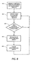
- an initial spatial arrangement may contain, for example, five Primary Objects "A”, “B”, “C”, “D” and “E”, identified as initial spatial arrangement 910.
- initial spatial arrangement 910 may contain any combination of text or graphical figures or elements.
- These Primary Objects support a first Composite Object 920 in an initial grouping structure. When some of the Primary Objects are moved a distance sufficient to destroy the group structure, two new spatial arrangements of Primary Objects are formed, arrangements 930 and 940.
- orientation, color, shape similarity, size similarity, or other properties may be used as criteria for destroying the group structure.
- Two new Composite Objects are then reconstituted such that spatial arrangement 930 is represented by new Composite Object 950 and spatial arrangement 940 is represented by new Composite Object 960.
- the flow diagram shows the procedure the processor follows in automatically reconstituting a grouping structure. Initially, the processor determines which, if any, Composite Objects are supported by moved Primary Objects at step 810 and identifies them as affected Composite Objects at step 820. The processor then determines whether the new locations of the moved Primary Objects are sufficiently removed from the original spatial arrangement so as to destroy group structure at step 830. If the processor determines that group structure has been destroyed, at step 840 the processor reconstitutes a new Composite Object containing those Primary Objects which were not moved. The processor then creates a new Composite Object supported by those Primary Objects that were moved at step 850 and returns to step 820 to repeat steps 820, 830, 840 and 850 for the next Composite Object.
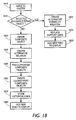
- the flow chart illustrates the steps for creation of a new primary object and revision of the composite object structure through use of a merge command.
- the user selects Primary Objects to be merged.
- the processor determines the bounding box for ' the union of the selected Primary Objects at step 1020.
- the bounding box will always be the minimum size to accommodate the union of the Primary Objects.
- a new blank bitmap corresponding to the size of the bounding box is created at step 1025.
- the processor copies the foreground material from all selected Primary Objects into the new bitmap and creates a new Primary Object for this new bitmap.
- the selected Primary Objects are then removed from the original Primary Object list at step 1040.
- the processor adds the new Primary Object to the original Primary Object list.
- the processor locates Composite Objects supported by all selected Primary Objects and identifies these as fully supported Composite Objects at step 1060.
- the processor replaces the support links from the selected Primary Objects with a support link to the new Primary Object at step 1070.
- the processor locates Composite Objects containing Primary Objects that are not part of the selected objects as well as a subset of selected Primary Objects and identifies these as partially-supported Composite Objects.
- the processor removes all support links to the Primary Objects to eliminate the partially-supported Composite Objects from the link graph representing the grouping structure at step 1090.
- a new Primary Object for the new bitmap is created.
- the union of "B” and “C” to form new Primary Object "F” results in the removal of the Primary Objects "B” and “C” from the Primary Object List at 1140 and the addition of the new Primary Object "F” to the Primary Object List at 1150.
- the partially-supported Composite Objects In the case in which the partially-supported Composite Objects are retained, only the support links to the selected Primary Objects are removed.
- the partially-supported Composite Object contained only one Primary Object other than a member of the selected Primary Objects, resulting in the elimination of Composite Object "CO2" from the grouping structure upon removal of the selected Primary Object support link, since a Composite Object must contain more than one Primary Object.
- the partially-supported Composite Object contains a plurality of non-selected Primary Objects in addition to a subset of the selected Primary Objects, when the support links to the selected Primary Objects are removed, the partially-supported Composite Object survives as a Composite Object containing the remaining non-selected Primary Objects.
- FIG. 12A shows nine possible Primary Objects "A”, “B”, “C”, “D”, “E”, “F”, “G”, “H” and “I” arranged in rows and columns and belonging to a Primary Object List. These Primary Objects may be grouped in a row type grouping illustrated in Figure 12B. Here Primary Objects “A”, “B” and “C” support Composite Object “R1”; Primary Objects “D”, E” and “F” support Composite Object “R2"; and Primary Objects "G”, “H” and “I” support Composite Object "R3".
- Figure 12C shows a column grouping in which Primary Objects "A”, “D” and “G” support Composite Object “C1”; Primary Objects “B”, “E” and “H” support Composite Object “C2"; and Primary Object “C”, “F” and “I” support Composite Object “C3".
- both groupings cannot be available simultaneously, in a lattice, as shown in Figure 12D.
- any unrestricted subset of primary objects can be grouped into a composite object such that primary objects may support multiple Composite Objects.
- Groups may be created in numerous ways, for example, the user may select a set of objects and establish them as a group that is independent of other groups of which these objects may be a member, through an explicit menu command. Alternatively, the user may select a set of objects and have the processor create a group automatically by virtue of the user's moving, rotating, scaling, or otherwise operating on the collection of objects. The processor may also create groups automatically by the application of image analysis processes that identify significant groups in the image. One approach to identifying groups of connected components that form words is illustrated in Figure 13.
- weighting may be stronger for one direction of link than for another. Weighting may be determined automatically or by spatial analysis of image material in the vicinity.
- the processor determines the weighted distance of the connected components and at step 1350 identifies those components whose weighted distance exceeds the threshold value. Those components whose weighted value exceeds the threshold value are removed from the possible group structure at step 1370.
- the processor accumulates groups by following the links among components. An example of this method is illustrated and discussed above with reference to Figure 9.
- a user may select a group and abolish it by an explicit menu command.
- the processor may automatically remove an object from a group when a user drags or moves an object sufficiently far from the other members of the group to which it belongs.
- tapping is generally used in reference to the physical act of touching the stylus of a pen-based computing system to the screen or tablet and shortly thereafter lifting the stylus from the screen (i.e. within a predetermined period of time) without moving the stylus any significant amount (i.e. less than a predetermined amount, as for example two pixels).
- This is a typical method of selecting objects in a pen-based computing system.
- clicking on is intended to be broader in scope and is intended to cover not only tapping, but also the action of selecting an object using a button associated with a mouse or track ball as well as the selection of an object using any other pointer device.
- any specific object may belong to numerous groups, with one method shown in Figure 14 for selecting groupings of image material shown in Figure 12. For example, when the user clicks or taps an object once, in this case "D" at step 1410, the item selected is "D". If the user clicks or taps "D" again, at step 1420, the next thing selected is the first in the list of groups of which that object is a member, in this example "C1". Subsequent clicks on the object, such as at step 1430, select the remaining groups that the object supports, for example "R2". Finally, after all the groups have been selected in this way, clicking or tapping the object as in step 1440 deselects everything and the process may begin again. In this way repeated clicks or taps allows the user to cycle through and identify the groups supported by the object.
- Grouping structures may also be used to edit selections, as illustrated in Figure 15.
- the user has created objects "A”, “B”, “C”, “D”, “E” and “F” at 1500, and object “C” happens to belong to a group containing objects "C” and “D”, but no other groups have been established.
- object "C” happens to belong to a group containing objects "C” and “D”, but no other groups have been established.
- the user wishes to select objects "A”, “B”, “E” and “F”
- one approach is to select object “A” by clicking on object "A” at step 1510.
- this object will be added to the set of selected objects, as is the case with "B” at step 1515, "E” at step 1520 and “F” at step 1525.
- the user could select all of the objects, perhaps by an encircling gesture, at step 1530 and then remove “C” and “D” individually by shift-clicking "C” at step 1535 and shift-clicking "D” at step 1540.
- Another alternative is to select all of the objects, perhaps by an encircling gesture, at step 1550, and then removing "C” and “D” as a group by shift-clicking "C” twice, as at steps 1555 and 1560. The first shift-click removes "C” from the selection. Subsequent shift-clicks on "C” de-selects groups to which "C” belongs, leaving objects "A", "B”, “E” and “F”, as shown in step 1560, as the remaining objects in the group.
- the ability to establish unidirectional or bi-directional hyperlinks between objects and destinations or sources is provided by the selection tools described herein, which are based on image processing and analysis technology. Beginning with an undifferentiated image, certain primitive image objects are automatically defined, and certain salient groupings of these are established. Using simple mouse and keyboard operations the user can easily establish additional image objects as Primary Image Objects or Composite Image Objects. The user may then select these objects, and the complex regions they define, simply by clicking a mouse over them.
- Figure 16 illustrates the method for creating bi-directional hyperlinks between objects and destinations or sources.
- any selected image object(s) may become the source or destination of a hyperlink.
- the link may be established by clicking the right mouse button, and selecting a "link" item form a pop-up menu, shown at step 1620.
- the user specifies where the link is to point at step 1630. This may be accomplished through a text entry box, or some other means known to the art.
- the system selects from among the available link source shapes (e.g. circle, rectangle, polygon) the one best suited to the selected image object(s) at step 1640.
- the parameters of this object are then automatically computed from the properties of the image region at step 1650.
- the points of a polygon selection shape are computed by sampling points from the convex hull, exterior bounding contour, or other derived geometrical approximation to the shape of the selected region.
- Links from image objects defined by multiple discontiguous image patches are supported by establishing multiple source regions all pointing to the same destination.
- any given image location may or may not support multiple hyperlinks.
- the subject invention provides richer link structure than the conventional hyperlinked document formats.
- This invention permits the selection of multiple groups sharing the same patch of image. The user may cycle through selected objects pertaining to a given location by repeatedly clicking the mouse button.
- this invention permits any selectable image object, including complex composite objects, to have their own independent hyperlinks.
- These links can be followed by an action other than a left mouse button click, for example a double-click, right button click, or right button click followed by selection of the link following through use of a pop-up menu.
- a contribution of the present invention is the provision for managing a lattice structure which represents multiple possible groupings of primitive image objects which may include pen strokes and bitmap objects.
- the user may easily substitute typed text for handwritten material such as handwritten notes, as illustrated in Figure 17.
- handwritten material 1710 in rough form is replaced by typewritten material 1720 and is associated with typewritten material 1720 through alternative formality relation 1730.
- OCR Optical Character Recognition
- the present invention augments this functionality in two ways. First, it incorporates the selection mechanisms described hereinabove.
- the system presents the user with not just a single choice of original image material to be replaced with typed text, but instead is able to choose exactly what image material is to be replaced. This is accomplished through use of any or all of the tools disclosed herein: rectangle dragging, freeform path dragging, polygon selection, selection of established primitive image objects with a single mouse click, selection of established groups of image objects with multiple mouse clicks, and editing of group structure by depressing a single prespecified key, such as the shift key, while performing selection operations. These operations make use of the lattice structure of relationships between primitive image objects and Composite Objects representing groupings of them.
- the user may commence typing text. Once text is entered, the selected image material is removed from the display and replaced with an image of the typed text.
- this functionality applies also in systems where some sort of automatic character recognition is provided.
- the user may invoke a character recognition system which would be applied to just the image material selected by the user.
- the user is able to simplify the job of any character recognition system by reducing the complexity of the image input material it is given to recognize, e.g. by isolating single words which OCR/ICR systems might recognize successfully in isolation but not when surrounded and intruded upon by extraneous image material.
- the present invention teaches a method for maintaining established group structure even while the user replaces source image material with typed text.
- the Primary Image Object e.g. Bitmap Objects
- the Primary Image Object which are to be replaced by typed text, may in many cases participate in groups, which are represented by Composite Objects. These groups should be preserved if possible even if the selected Bitmap Objects are removed and replaced with typed text.
- typed text is entered into the display using a special kind of Bitmap Object called a Text String Bitmap Object.
- This is a Bitmap Object which is associated with a set of ascii characters plus typography information such as font family, font size, font color, etc.
- the textual characters and typography information permit this Bitmap Object to be modified by the user in terms of its formatted textual appearance.
- a Composite Object corresponding to the collection of selected Bitmap Objects is identified. This is illustrated in Figure 19 at grouping diagram 1920, in which Composite Object CO3 is the Composite Object for selected Bitmap Objects BO3, BO4 and BO5.
- the processor identifies Composite Objects whose support does not include the entire set of selected Bitmap Objects and removes the links to the non-selected Bitmap Objects supporting these Composite Objects. These are stored as historical links, to be restored in the event that the replacing typed text in the display is itself replaced by the original informal Bitmap Objects it replaced.
- This is illustrated in Figure 19 at grouping diagram 1950, in which Composite Object CO1 is identified as the Composite Object whose support does not include the entire set of selected Bitmap Objects, but does include additional Bitmap Objects, in this case BO1 and BO2.
- the links to non-selected Bitmap Objects BO1 and BO2 have been removed and replaced by historical links 1952 and 1954.
- the full link between Composite Object CO2 and Bitmap Object BO2 has also been replaced with historical link 1958, and the alternative formality relation 1956 continues to exist between Composite Object CO3 and the TSBO.
- the processor removes the selected Bitmap Object from the display and replaces it with the new TSBO.
- Figure 20 illustrates this in grouping diagram 2030, in which the selected Bitmap Object BO9 is no longer visible to the user in the display, having been replaced by the TSBO.
- the result of the procedure described above is a reconfigured structure lattice, whereby the TSBO replaces the selected Bitmap Objects in the list of displayed image objects visible in the display, while groups involving the selected Bitmap Objects now become associated with the TSBO.
- This structure leaves "historical links", which preserve the information about the original groupings. This permits the TSBO to be exchanged and the original Bitmap Objects it replaced to be restored, with all of their prior grouping structure.
Landscapes
- Physics & Mathematics (AREA)
- General Physics & Mathematics (AREA)
- Engineering & Computer Science (AREA)
- Theoretical Computer Science (AREA)
- Processing Or Creating Images (AREA)
- Image Processing (AREA)
- Editing Of Facsimile Originals (AREA)
- Record Information Processing For Printing (AREA)
Abstract
Description
Claims (14)
- A method for organizing a source electronic image entered on a display device into meaningful image objects comprising:selecting arbitrary existing image material;establishing primary image objects;modifying the image material; andreconstituting an unrestricted grouping structure.
- A method according to claim 1, further comprising distinguishing foreground pixels of text and line art from background pixels.
- A method according to claim 1 or claim 2, further comprising creating not less than one primary image object representing the preprocessed source image, in which background pixels are set as transparent.
- A method according to any of the preceding claims, wherein said selecting existing image material comprises inputting a closed path enclosing the desired image material.
- A method according to any or the preceding claims, wherein said selecting existing image material comprises splitting at least one primary object to form fragmented primary image objects.
- A method according to claim 4 and claim 5, further comprising creating a new composite object by:gathering fragmented primary objects and remaining unfragmented primary objects enclosed by said closed selection path to form enclosed primary objects;creating a provisional composite object representing the group of enclosed primary objects;removing affected primary objects from a primary object list;adding fragmented primary objects to said primary object list; andcreating support links to enclosed primary objects.
- A method according to any of the preceding claims, wherein reconstituting the unrestricted grouping structure comprises:identifying composite objects supported by a plurality of primary image objects;moving not less than one primary image object;determining whether the new location of the moved primary image objects destroys group structure;forming a new composite object with those primary image objects not moved;creating a new composite object for primary image objects that were moved; andcreating a new grouping structure.
- A method according to any of the preceding claims, further comprising establishing a new primary image object by merging not less than two primary image objects by:selecting at least one primary image object;determining the bounding box of the union of the selected primary image objects;creating a new blank bitmap corresponding to the size of said bounding box;copying foreground material from all selected primary image objects into said new bitmap;creating a new primary image object of said new bitmap;selected primary image objects from a primary object list; andadding new primary object to said primary object list.
- A method according to any of the preceding claims, further comprising creating new composite objects by:locating composite objects supported by all selected primary objects to form fully supported composite objects;replacing support links from said selected primary objects with support links to a new primary object for each said fully supported composite object;locating composite objects supported by a subset of selected primary objects to form partially supported composite objects; andremoving all support links to primary objects for each partially supported composite object.
- A method according to any of the preceding claims, further comprising:segmenting image regions into text and line art, continuous tone/photographic, and halftone subregions;creating separate bitmap objects for said continuous tone and said halftone regions;deleting said separate bitmap objects from the source image;breaking the processed source image into a plurality of elemental bitmap objects to form primary objects; andidentifying collections of bitmap objects into composite objects, or groups, within a lattice grouping structure.
- A graphical input and display system for creating and manipulating an electronic image, comprising:user input means for manipulating elements of the electronic image;image input means for entering the electronic image onto a display means;a processor, connected for receiving requests for image editing operations and for accessing a memory structure;program memory means comprising:user interaction module for entering new image material or selecting and modifying existing image material to form primary image objects;grouping module for creating visible image elements and maintaining an unrestricted grouping structure;data output module for presenting a view of the graphical image; anddata memory means comprising:data input data structure; anddata output data structure.
- The graphical input and display system according to claim 11, further comprising a segmentation module for automatically decomposing image material into primary image objects, including a plurality of elemental bitmap objects and curvilinear bitmap objects.
- A system according to claim 11 or claim 12, adapted to carry out a method according to any of claims 1 to 10.
- A computer program product comprising a computer usable medium having computer readable program code embodied in said medium which, when said program code is executed by said computer causes said computer to perform method steps for editing and manipulating an electronic image entered onto a display, said method steps comprising:decomposing the electronic image into primary image objects;organizing said primary image objects into unrestricted groups of primary image objects, such that each said primary image object belongs to one or more groups and each group contains not less than one primary image object;creating new primary image objects; andreorganizing all or part of said groups of primary image objects into one or more new groups of primary image objects in response to user manipulation of not less than one primary image object.
Applications Claiming Priority (2)
| Application Number | Priority Date | Filing Date | Title |
|---|---|---|---|
| US104805 | 2002-03-22 | ||
| US10/104,805 US6903751B2 (en) | 2002-03-22 | 2002-03-22 | System and method for editing electronic images |
Publications (3)
| Publication Number | Publication Date |
|---|---|
| EP1361544A2 true EP1361544A2 (en) | 2003-11-12 |
| EP1361544A3 EP1361544A3 (en) | 2004-06-23 |
| EP1361544B1 EP1361544B1 (en) | 2010-10-06 |
Family
ID=28040696
Family Applications (1)
| Application Number | Title | Priority Date | Filing Date |
|---|---|---|---|
| EP03251707A Expired - Lifetime EP1361544B1 (en) | 2002-03-22 | 2003-03-19 | System and method for editing electronic images |
Country Status (4)
| Country | Link |
|---|---|
| US (1) | US6903751B2 (en) |
| EP (1) | EP1361544B1 (en) |
| JP (1) | JP2003298837A (en) |
| DE (1) | DE60334420D1 (en) |
Families Citing this family (83)
| Publication number | Priority date | Publication date | Assignee | Title |
|---|---|---|---|---|
| US7251775B1 (en) * | 2000-06-30 | 2007-07-31 | Nokia Corporation | System and method for visual history presentation and management |
| US7246321B2 (en) * | 2001-07-13 | 2007-07-17 | Anoto Ab | Editing data |
| US7158675B2 (en) * | 2002-05-14 | 2007-01-02 | Microsoft Corporation | Interfacing with ink |
| US7925987B2 (en) * | 2002-05-14 | 2011-04-12 | Microsoft Corporation | Entry and editing of electronic ink |
| US20030214553A1 (en) * | 2002-05-14 | 2003-11-20 | Microsoft Corporation | Ink regions in an overlay control |
| US8166388B2 (en) | 2002-05-14 | 2012-04-24 | Microsoft Corporation | Overlaying electronic ink |
| US7299424B2 (en) * | 2002-05-14 | 2007-11-20 | Microsoft Corporation | Lasso select |
| US20040054509A1 (en) * | 2002-09-12 | 2004-03-18 | Breit Stephen R. | System and method for preparing a solid model for meshing |
| US20040066538A1 (en) * | 2002-10-04 | 2004-04-08 | Rozzi William A. | Conversion of halftone bitmaps to continuous tone representations |
| US7310769B1 (en) * | 2003-03-12 | 2007-12-18 | Adobe Systems Incorporated | Text encoding using dummy font |
| US7505048B2 (en) * | 2003-04-25 | 2009-03-17 | Microsoft Corporation | Estimation of overlap of polygons |
| US20050068312A1 (en) * | 2003-09-26 | 2005-03-31 | Denny Jaeger | Method for programming a graphic control device with numeric and textual characters |
| US7154511B2 (en) * | 2003-10-24 | 2006-12-26 | Microsoft Corporation | Fast rendering of ink |
| US8074184B2 (en) * | 2003-11-07 | 2011-12-06 | Mocrosoft Corporation | Modifying electronic documents with recognized content or other associated data |
| US7421116B2 (en) * | 2004-03-25 | 2008-09-02 | Hewlett-Packard Development Company, L.P. | Image processing methods and systems |
| JP2006018522A (en) * | 2004-06-30 | 2006-01-19 | Canon Inc | Image edition system, method, and program |
| US9799148B2 (en) * | 2005-04-04 | 2017-10-24 | Psi Systems, Inc. | Systems and methods for establishing the colors of a customized stamp |
| US8514447B2 (en) * | 2005-06-07 | 2013-08-20 | Canon Kabushiki Kaisha | Image processing using first and second color matching |
| US7778492B2 (en) | 2006-04-04 | 2010-08-17 | Oldford Group Limited | System and method for scaling digital images |
| US7876335B1 (en) | 2006-06-02 | 2011-01-25 | Adobe Systems Incorporated | Methods and apparatus for redacting content in a document |
| US8072472B2 (en) * | 2006-06-26 | 2011-12-06 | Agfa Healthcare Inc. | System and method for scaling overlay images |
| US9805010B2 (en) | 2006-06-28 | 2017-10-31 | Adobe Systems Incorporated | Methods and apparatus for redacting related content in a document |
| JP4743154B2 (en) * | 2006-07-05 | 2011-08-10 | セイコーエプソン株式会社 | Document editing apparatus, program, and storage medium |
| KR100931994B1 (en) * | 2006-07-12 | 2009-12-15 | 삼성전자주식회사 | Image processing device and image processing method |
| US8612847B2 (en) * | 2006-10-03 | 2013-12-17 | Adobe Systems Incorporated | Embedding rendering interface |
| CN101192107A (en) * | 2006-11-28 | 2008-06-04 | 国际商业机器公司 | Method and apparatus for inputting |
| US7725493B2 (en) * | 2007-03-23 | 2010-05-25 | Palo Alto Research Center Incorporated | Optimization method and process using tree searching operation and non-overlapping support constraint requirements |
| US8014607B2 (en) * | 2007-03-23 | 2011-09-06 | Palo Alto Research Center Incorporated | Method and apparatus for creating and editing node-link diagrams in pen computing systems |
| US7907141B2 (en) * | 2007-03-23 | 2011-03-15 | Palo Alto Research Center Incorporated | Methods and processes for recognition of electronic ink strokes |
| US8407589B2 (en) * | 2007-04-20 | 2013-03-26 | Microsoft Corporation | Grouping writing regions of digital ink |
| JP4942193B2 (en) * | 2007-06-22 | 2012-05-30 | キヤノン株式会社 | Information processing apparatus and information processing method |
| US20090073188A1 (en) * | 2007-09-13 | 2009-03-19 | James Williams | System and method of modifying illustrations using scaleable vector graphics |
| US8009330B2 (en) * | 2008-02-05 | 2011-08-30 | Eastman Kodak Company | Method for imaging flexographic plates |
| US8170380B1 (en) * | 2008-05-30 | 2012-05-01 | Adobe Systems Incorporated | Method and apparatus for importing, exporting and determining an initial state for files having multiple layers |
| US20100229129A1 (en) * | 2009-03-04 | 2010-09-09 | Microsoft Corporation | Creating organizational containers on a graphical user interface |
| US8452086B2 (en) * | 2009-07-10 | 2013-05-28 | Palo Alto Research Center Incorporated | System and user interface for machine-assisted human labeling of pixels in an image |
| US8649600B2 (en) * | 2009-07-10 | 2014-02-11 | Palo Alto Research Center Incorporated | System and method for segmenting text lines in documents |
| US8442319B2 (en) * | 2009-07-10 | 2013-05-14 | Palo Alto Research Center Incorporated | System and method for classifying connected groups of foreground pixels in scanned document images according to the type of marking |
| US9535599B2 (en) * | 2009-08-18 | 2017-01-03 | Adobe Systems Incorporated | Methods and apparatus for image editing using multitouch gestures |
| US9310907B2 (en) | 2009-09-25 | 2016-04-12 | Apple Inc. | Device, method, and graphical user interface for manipulating user interface objects |
| EP2480957B1 (en) | 2009-09-22 | 2017-08-09 | Apple Inc. | Device, method, and graphical user interface for manipulating user interface objects |
| US8766928B2 (en) | 2009-09-25 | 2014-07-01 | Apple Inc. | Device, method, and graphical user interface for manipulating user interface objects |
| US8799826B2 (en) | 2009-09-25 | 2014-08-05 | Apple Inc. | Device, method, and graphical user interface for moving a calendar entry in a calendar application |
| US8832585B2 (en) | 2009-09-25 | 2014-09-09 | Apple Inc. | Device, method, and graphical user interface for manipulating workspace views |
| US8698747B1 (en) | 2009-10-12 | 2014-04-15 | Mattel, Inc. | Hand-activated controller |
| US8539385B2 (en) | 2010-01-26 | 2013-09-17 | Apple Inc. | Device, method, and graphical user interface for precise positioning of objects |
| US8677268B2 (en) * | 2010-01-26 | 2014-03-18 | Apple Inc. | Device, method, and graphical user interface for resizing objects |
| US8539386B2 (en) * | 2010-01-26 | 2013-09-17 | Apple Inc. | Device, method, and graphical user interface for selecting and moving objects |
| US20130111380A1 (en) * | 2010-04-02 | 2013-05-02 | Symantec Corporation | Digital whiteboard implementation |
| US9098182B2 (en) | 2010-07-30 | 2015-08-04 | Apple Inc. | Device, method, and graphical user interface for copying user interface objects between content regions |
| US9081494B2 (en) | 2010-07-30 | 2015-07-14 | Apple Inc. | Device, method, and graphical user interface for copying formatting attributes |
| US8972879B2 (en) | 2010-07-30 | 2015-03-03 | Apple Inc. | Device, method, and graphical user interface for reordering the front-to-back positions of objects |
| KR20120013807A (en) * | 2010-08-06 | 2012-02-15 | 엘지전자 주식회사 | Mobile terminal providing lighting and highlight function and control method thereof |
| WO2012037721A1 (en) * | 2010-09-21 | 2012-03-29 | Hewlett-Packard Development Company,L.P. | Handwritten character font library |
| US9323807B2 (en) * | 2010-11-03 | 2016-04-26 | Sap Se | Graphical manipulation of data objects |
| US8699078B2 (en) * | 2010-11-18 | 2014-04-15 | Fuji Xerox Co., Ltd. | Image processing apparatus, image processing method, and computer readable medium storing program |
| US20120206471A1 (en) * | 2011-02-11 | 2012-08-16 | Apple Inc. | Systems, methods, and computer-readable media for managing layers of graphical object data |
| US8548280B2 (en) * | 2011-02-14 | 2013-10-01 | Hewlett-Packard Development Company, L.P. | Systems and methods for replacing non-image text |
| US9665941B2 (en) * | 2012-10-30 | 2017-05-30 | Hewlett-Packard Development Company, L.P. | Object segmentation |
| JP5690317B2 (en) * | 2012-11-01 | 2015-03-25 | シャープ株式会社 | Information display device and information display method |
| US8948509B2 (en) * | 2012-11-15 | 2015-02-03 | Adobe Systems Incorported | Blending with multiple blend modes for image manipulation |
| JP6201488B2 (en) * | 2013-07-29 | 2017-09-27 | 富士通株式会社 | Selected character identification program, selected character identification method, and selected character identification device |
| US9105094B2 (en) * | 2013-10-01 | 2015-08-11 | Adobe Systems Incorporated | Image layers navigation |
| US10176611B2 (en) * | 2013-10-21 | 2019-01-08 | Cellco Partnership | Layer-based image updates |
| US10296570B2 (en) | 2013-10-25 | 2019-05-21 | Palo Alto Research Center Incorporated | Reflow narrative text objects in a document having text objects and graphical objects, wherein text object are classified as either narrative text object or annotative text object based on the distance from a left edge of a canvas of display |
| US9659279B2 (en) | 2013-10-25 | 2017-05-23 | Palo Alto Research Center Incorporated | Method and system for enhanced inferred mode user interface operations |
| US9710879B2 (en) * | 2014-09-08 | 2017-07-18 | Ross Video Limited | Methods and systems for computing an alpha channel value |
| US9864479B2 (en) | 2014-12-19 | 2018-01-09 | Xerox Corporation | System and method for managing and reviewing document integration and updates |
| US10136103B2 (en) | 2015-11-23 | 2018-11-20 | Lexmark International, Inc. | Identifying consumer products in images |
| US9990561B2 (en) * | 2015-11-23 | 2018-06-05 | Lexmark International, Inc. | Identifying consumer products in images |
| US10755029B1 (en) | 2016-01-05 | 2020-08-25 | Quirklogic, Inc. | Evaluating and formatting handwritten input in a cell of a virtual canvas |
| US10067731B2 (en) | 2016-01-05 | 2018-09-04 | Quirklogic, Inc. | Method and system for representing a shared digital virtual “absolute” canvas |
| US10324618B1 (en) * | 2016-01-05 | 2019-06-18 | Quirklogic, Inc. | System and method for formatting and manipulating digital ink |
| US10129335B2 (en) | 2016-01-05 | 2018-11-13 | Quirklogic, Inc. | Method and system for dynamic group creation in a collaboration framework |
| DE102016201389A1 (en) * | 2016-01-29 | 2017-08-03 | Robert Bosch Gmbh | Method for recognizing objects, in particular of three-dimensional objects |
| WO2018085929A1 (en) * | 2016-11-09 | 2018-05-17 | Quirklogic, Inc. | Method and system for erasing an enclosed area on an interactive display |
| US10895954B2 (en) * | 2017-06-02 | 2021-01-19 | Apple Inc. | Providing a graphical canvas for handwritten input |
| US11069044B1 (en) * | 2020-03-18 | 2021-07-20 | Adobe Inc. | Eliminating image artifacts using image-layer snapshots |
| US11587346B2 (en) | 2020-12-10 | 2023-02-21 | Microsoft Technology Licensing, Llc | Detecting ink gestures based on spatial and image data processing |
| US11531454B2 (en) * | 2020-12-10 | 2022-12-20 | Microsoft Technology Licensing, Llc | Selecting content in ink documents using a hierarchical data structure |
| CN112734882B (en) * | 2020-12-30 | 2024-03-05 | 维沃移动通信有限公司 | Image processing method and device |
| US11631206B2 (en) * | 2021-06-10 | 2023-04-18 | Adobe Inc. | Glyph selection tool for digital text content |
| US20230315271A1 (en) * | 2022-03-18 | 2023-10-05 | Sony Group Corporation | Collaborative whiteboard for meetings |
Family Cites Families (21)
| Publication number | Priority date | Publication date | Assignee | Title |
|---|---|---|---|---|
| DE3729023C2 (en) | 1986-08-29 | 1995-03-16 | Canon Kk | Imaging device |
| CA2027253C (en) | 1989-12-29 | 1997-12-16 | Steven C. Bagley | Editing text in an image |
| FR2681967B1 (en) * | 1991-10-01 | 1994-11-25 | Electronics For Imaging Inc | METHOD AND APPARATUS FOR CHANGING THE COLORS OF AN IMAGE USING A COMPUTER. |
| US5345313A (en) * | 1992-02-25 | 1994-09-06 | Imageware Software, Inc | Image editing system for taking a background and inserting part of an image therein |
| US5926186A (en) | 1992-09-10 | 1999-07-20 | Fujitsu Limited | Graphic editing apparatus and method |
| US6535897B1 (en) * | 1993-05-20 | 2003-03-18 | Microsoft Corporation | System and methods for spacing, storing and recognizing electronic representations of handwriting printing and drawings |
| US5553224A (en) * | 1993-08-04 | 1996-09-03 | Xerox Corporation | Method for dynamically maintaining multiple structural interpretations in graphics system |
| US7859551B2 (en) * | 1993-10-15 | 2010-12-28 | Bulman Richard L | Object customization and presentation system |
| US5664180A (en) * | 1995-03-20 | 1997-09-02 | Framework Technologies Corporation | Design tool for complex objects which links object structures of a design object in multiple design domains |
| JP3378900B2 (en) | 1996-06-25 | 2003-02-17 | 富士通株式会社 | Object editing method, object editing system, and recording medium |
| US5784061A (en) | 1996-06-26 | 1998-07-21 | Xerox Corporation | Method and apparatus for collapsing and expanding selected regions on a work space of a computer controlled display system |
| US5861886A (en) * | 1996-06-26 | 1999-01-19 | Xerox Corporation | Method and apparatus for grouping graphic objects on a computer based system having a graphical user interface |
| US5974198A (en) | 1996-08-26 | 1999-10-26 | Adobe Systems Incorporated | Adjustment layers for composited image manipulation |
| US5912668A (en) | 1997-05-30 | 1999-06-15 | Sony Corporation | Controlling a screen display of a group of images represented by a graphical object |
| US5889523A (en) | 1997-11-25 | 1999-03-30 | Fuji Xerox Co., Ltd. | Method and apparatus for dynamically grouping a plurality of graphic objects |
| US6028583A (en) | 1998-01-16 | 2000-02-22 | Adobe Systems, Inc. | Compound layers for composited image manipulation |
| US6459442B1 (en) * | 1999-09-10 | 2002-10-01 | Xerox Corporation | System for applying application behaviors to freeform data |
| US20020175948A1 (en) * | 2001-05-23 | 2002-11-28 | Nielsen Eric W. | Graphical user interface method and apparatus for interaction with finite element analysis applications |
| US6704467B2 (en) * | 2000-12-21 | 2004-03-09 | Canon Kabushiki Kaisha | Image editing with block selection |
| US6816612B2 (en) * | 2001-06-29 | 2004-11-09 | Mustek Systems Inc. | Multi-mode image processing method and a system thereof |
| US7194140B2 (en) * | 2001-11-05 | 2007-03-20 | Canon Kabushiki Kaisha | Image processing apparatus and method which compresses image data of each region using a selected encoding method |
-
2002
- 2002-03-22 US US10/104,805 patent/US6903751B2/en not_active Expired - Lifetime
-
2003
- 2003-03-19 DE DE60334420T patent/DE60334420D1/en not_active Expired - Lifetime
- 2003-03-19 EP EP03251707A patent/EP1361544B1/en not_active Expired - Lifetime
- 2003-03-20 JP JP2003076852A patent/JP2003298837A/en active Pending
Also Published As
| Publication number | Publication date |
|---|---|
| US20030179214A1 (en) | 2003-09-25 |
| DE60334420D1 (en) | 2010-11-18 |
| EP1361544B1 (en) | 2010-10-06 |
| JP2003298837A (en) | 2003-10-17 |
| EP1361544A3 (en) | 2004-06-23 |
| US6903751B2 (en) | 2005-06-07 |
Similar Documents
| Publication | Publication Date | Title |
|---|---|---|
| EP1361544B1 (en) | System and method for editing electronic images | |
| EP0434930B1 (en) | Editing text in an image | |
| EP0439951B1 (en) | Data processing | |
| US5465304A (en) | Segmentation of text, picture and lines of a document image | |
| US8875016B2 (en) | Method and apparatus to convert digital ink images for use in a structured text/graphics editor | |
| DE69230635T2 (en) | Process and device for image / hand marking determination | |
| EP1999688B1 (en) | Converting digital images containing text to token-based files for rendering | |
| US8634644B2 (en) | System and method for identifying pictures in documents | |
| US7576753B2 (en) | Method and apparatus to convert bitmapped images for use in a structured text/graphics editor | |
| US6768816B2 (en) | Method and system for interactive ground-truthing of document images | |
| EP1457917B1 (en) | Apparatus and methods for converting network drawings from raster format to vector format | |
| US6952803B1 (en) | Method and system for transcribing and editing using a structured freeform editor | |
| US7093202B2 (en) | Method and system for interpreting imprecise object selection paths | |
| EP0543598A2 (en) | Method and apparatus for document image processing | |
| US20120250048A1 (en) | Image processing apparatus and image processing method | |
| JPH05242300A (en) | Method for processing document image | |
| JP5824309B2 (en) | Image processing apparatus, image processing method, and program | |
| Baloun et al. | ChronSeg: Novel Dataset for Segmentation of Handwritten Historical Chronicles. | |
| Li | An implementation of ocr system based on skeleton matching | |
| JP4574347B2 (en) | Image processing apparatus, method, and program | |
| Cinque et al. | Understanding the page logical structure | |
| JPS63155385A (en) | Optical character reader | |
| JPH0433079A (en) | Table processing system |
Legal Events
| Date | Code | Title | Description |
|---|---|---|---|
| PUAI | Public reference made under article 153(3) epc to a published international application that has entered the european phase |
Free format text: ORIGINAL CODE: 0009012 |
|
| AK | Designated contracting states |
Kind code of ref document: A2 Designated state(s): AT BE BG CH CY CZ DE DK EE ES FI FR GB GR HU IE IT LI LU MC NL PT RO SE SI SK TR |
|
| AX | Request for extension of the european patent |
Extension state: AL LT LV MK |
|
| PUAL | Search report despatched |
Free format text: ORIGINAL CODE: 0009013 |
|
| AK | Designated contracting states |
Kind code of ref document: A3 Designated state(s): AT BE BG CH CY CZ DE DK EE ES FI FR GB GR HU IE IT LI LU MC NL PT RO SE SI SK TR |
|
| AX | Request for extension of the european patent |
Extension state: AL LT LV MK |
|
| 17P | Request for examination filed |
Effective date: 20041223 |
|
| AKX | Designation fees paid |
Designated state(s): DE FR GB |
|
| GRAP | Despatch of communication of intention to grant a patent |
Free format text: ORIGINAL CODE: EPIDOSNIGR1 |
|
| GRAS | Grant fee paid |
Free format text: ORIGINAL CODE: EPIDOSNIGR3 |
|
| GRAA | (expected) grant |
Free format text: ORIGINAL CODE: 0009210 |
|
| AK | Designated contracting states |
Kind code of ref document: B1 Designated state(s): DE FR GB |
|
| REG | Reference to a national code |
Ref country code: GB Ref legal event code: FG4D |
|
| REF | Corresponds to: |
Ref document number: 60334420 Country of ref document: DE Date of ref document: 20101118 Kind code of ref document: P |
|
| PLBE | No opposition filed within time limit |
Free format text: ORIGINAL CODE: 0009261 |
|
| STAA | Information on the status of an ep patent application or granted ep patent |
Free format text: STATUS: NO OPPOSITION FILED WITHIN TIME LIMIT |
|
| 26N | No opposition filed |
Effective date: 20110707 |
|
| REG | Reference to a national code |
Ref country code: DE Ref legal event code: R097 Ref document number: 60334420 Country of ref document: DE Effective date: 20110707 |
|
| REG | Reference to a national code |
Ref country code: FR Ref legal event code: PLFP Year of fee payment: 14 |
|
| REG | Reference to a national code |
Ref country code: FR Ref legal event code: PLFP Year of fee payment: 15 |
|
| REG | Reference to a national code |
Ref country code: FR Ref legal event code: PLFP Year of fee payment: 16 |
|
| PGFP | Annual fee paid to national office [announced via postgrant information from national office to epo] |
Ref country code: GB Payment date: 20190222 Year of fee payment: 17 Ref country code: DE Payment date: 20190219 Year of fee payment: 17 |
|
| PGFP | Annual fee paid to national office [announced via postgrant information from national office to epo] |
Ref country code: FR Payment date: 20190220 Year of fee payment: 17 |
|
| REG | Reference to a national code |
Ref country code: DE Ref legal event code: R119 Ref document number: 60334420 Country of ref document: DE |
|
| PG25 | Lapsed in a contracting state [announced via postgrant information from national office to epo] |
Ref country code: FR Free format text: LAPSE BECAUSE OF NON-PAYMENT OF DUE FEES Effective date: 20200331 Ref country code: DE Free format text: LAPSE BECAUSE OF NON-PAYMENT OF DUE FEES Effective date: 20201001 |
|
| GBPC | Gb: european patent ceased through non-payment of renewal fee |
Effective date: 20200319 |
|
| PG25 | Lapsed in a contracting state [announced via postgrant information from national office to epo] |
Ref country code: GB Free format text: LAPSE BECAUSE OF NON-PAYMENT OF DUE FEES Effective date: 20200319 |