EP1361384A2 - Tuyau flexible de protection pour le logement des conduites - Google Patents
Tuyau flexible de protection pour le logement des conduites Download PDFInfo
- Publication number
- EP1361384A2 EP1361384A2 EP03010167A EP03010167A EP1361384A2 EP 1361384 A2 EP1361384 A2 EP 1361384A2 EP 03010167 A EP03010167 A EP 03010167A EP 03010167 A EP03010167 A EP 03010167A EP 1361384 A2 EP1361384 A2 EP 1361384A2
- Authority
- EP
- European Patent Office
- Prior art keywords
- hose
- protective
- protective tube
- axially
- tube
- Prior art date
- Legal status (The legal status is an assumption and is not a legal conclusion. Google has not performed a legal analysis and makes no representation as to the accuracy of the status listed.)
- Granted
Links
Images


Classifications
-
- F—MECHANICAL ENGINEERING; LIGHTING; HEATING; WEAPONS; BLASTING
- F16—ENGINEERING ELEMENTS AND UNITS; GENERAL MEASURES FOR PRODUCING AND MAINTAINING EFFECTIVE FUNCTIONING OF MACHINES OR INSTALLATIONS; THERMAL INSULATION IN GENERAL
- F16L—PIPES; JOINTS OR FITTINGS FOR PIPES; SUPPORTS FOR PIPES, CABLES OR PROTECTIVE TUBING; MEANS FOR THERMAL INSULATION IN GENERAL
- F16L3/00—Supports for pipes, cables or protective tubing, e.g. hangers, holders, clamps, cleats, clips, brackets
- F16L3/26—Supports for pipes, cables or protective tubing, e.g. hangers, holders, clamps, cleats, clips, brackets specially adapted for supporting the pipes all along their length, e.g. pipe channels or ducts
-
- F—MECHANICAL ENGINEERING; LIGHTING; HEATING; WEAPONS; BLASTING
- F16—ENGINEERING ELEMENTS AND UNITS; GENERAL MEASURES FOR PRODUCING AND MAINTAINING EFFECTIVE FUNCTIONING OF MACHINES OR INSTALLATIONS; THERMAL INSULATION IN GENERAL
- F16L—PIPES; JOINTS OR FITTINGS FOR PIPES; SUPPORTS FOR PIPES, CABLES OR PROTECTIVE TUBING; MEANS FOR THERMAL INSULATION IN GENERAL
- F16L27/00—Adjustable joints; Joints allowing movement
- F16L27/08—Adjustable joints; Joints allowing movement allowing adjustment or movement only about the axis of one pipe
-
- F—MECHANICAL ENGINEERING; LIGHTING; HEATING; WEAPONS; BLASTING
- F16—ENGINEERING ELEMENTS AND UNITS; GENERAL MEASURES FOR PRODUCING AND MAINTAINING EFFECTIVE FUNCTIONING OF MACHINES OR INSTALLATIONS; THERMAL INSULATION IN GENERAL
- F16L—PIPES; JOINTS OR FITTINGS FOR PIPES; SUPPORTS FOR PIPES, CABLES OR PROTECTIVE TUBING; MEANS FOR THERMAL INSULATION IN GENERAL
- F16L3/00—Supports for pipes, cables or protective tubing, e.g. hangers, holders, clamps, cleats, clips, brackets
- F16L3/16—Supports for pipes, cables or protective tubing, e.g. hangers, holders, clamps, cleats, clips, brackets with special provision allowing movement of the pipe
Definitions
- the invention relates to a protective hose with lines therein for industrial robots.
- a protective hose with lines in it that are used for supply a tool that is carried by the industrial robot is also used as Hose package called.
- the lines lying in the protective tube include, for example the power supply for a tool, for example a spot welding tool, such as control cables, air lines, hydraulic lines and cooling water lines.
- the protective hose serves to hold the lines running in it together, so that these do not significantly affect the movements of the industrial robot or the Do not increase the space requirement of the industrial robot excessively, but also as a mechanical one Protection of the lines in the protective hose.
- the arm links of the robot move against each other Swiveling, axial rotational movements and / or moving against each other to the to bring tools carried by the robot into different positions.
- the protective hose with the lines in it must be the movements of the arm links of the robot follow to ensure a connection to the tool.
- Another known remedy for the premature breakage of the lines or the protective hose To prevent this is to protect the protective hose in a mechanical tracking device to keep it in the event of a tensile load on the lines or the Protective tube allows the protective tube to be pulled along, for example if that The tool is extended, but the protective hose when the tensile load decreases is brought back again to avoid sagging and kinking.
- the solution according to the invention is a protective hose for holding lines
- the protective tube having at least one cuff component has by being axially rotatable.
- the protective tube is of a sleeve component surround, for example, a pipe section lying outside, the ends of which one have increasing diameter and the protective tube in the sleeve component is interrupted so that two adjacent hose section ends arise and at least one of these hose section ends is axially rotatably supported in the sleeve component is.
- the protective tube has an interruption in shape two adjacent hose section ends, is in this area of the cuff component surrounded and both adjacent hose section ends are independent of each other axially rotatably supported in the cuff member.
- Such storage can by rolling bearings, for example ball bearings, deep groove ball bearings, needle bearings or roller bearings, the axial and / or radial loads take place, which are arranged in the sleeve component are and surround the hose section ends.
- the hose section ends can also be encompassed by an end sleeve in the rolling bearing in the sleeve component is arranged, is stored.
- the protective tube according to the invention enables the protective tube to be relieved of Torsional stresses that occur because the protective tube prevents the movements of the Arm links of an industrial robot follows.
- Protective hose also relieves the lines in it of tension and / or Torsion stresses reached, so that both the protective hose according to the invention itself as well as the lines routed in it compared to conventional hose packages have a longer lifespan.
- the protective hose for receiving lines has at least a device for local attachment to mutually movable arm members, for example of an industrial robot, with the protective tube in this at least one Device for local attachment is rotatably mounted.
- a device for local Attachment can be a cuff component that covers the protective tube in one area surrounds.
- An embodiment of this embodiment provides that the protective tube in the at least one device for local attachment, for example a cuff component, each has an interruption in which two hose section ends opposite and at least one of the hose section ends in the device for local attachment is axially rotatably mounted.
- Another preferred embodiment provides before that both hose section ends opposite each other in the interruption are axially rotatably supported independently of one another in the sleeve component.
- the protective tube is for Inclusion of lines with at least one device for local attachment to each other movable arm members, such as an industrial robot attached, wherein the protective tube in a distance from the device for local attachment Area has an interruption.
- This break is caused by two adjacent ones Hose section ends, which face each other, and is formed by an axially arranged Surround cuff component, with at least one of the adjacent hose section ends is axially rotatably supported in the cuff member.
- the two adjacent hose section ends are the are surrounded by the sleeve component, independently of one another in the axially rotatable Cuff component stored.
- the protective tube according to the invention comprises a sleeve component, in which it is both axially rotatable and movable in the direction of the axis
- a cuff component is on an arm link of an industrial robot attached, and the protective tube is rotatable in the sleeve component and in the longitudinal direction kept slidable.
- Longitudinal guides are suitable for this storage Include protective tube at least partially circumferentially, such as flat guides, in particular ball guides, which consist of an outer bush, a cage with balls and an inner socket.
- ball guides can also be used instead of an outer bush can be contained directly in the cuff component, the hose can also be used without an inner sleeve be stored directly on the balls.
- a ball sleeve can be attached to three or more ball grooves with feedback.
- Roller guides are also suitable, with, for example, ladder-shaped flat cages or in the form of a roller shoe.
- the sleeve component is a ball bearing with such a large internal cross section, in which the protective tube in the longitudinal direction is movable and is therefore kept slidable. Offers a special advantage this type of rotatable bearing in a cuff component when the protective tube is held under tension by a return spring so that the return spring the protective tube pulls in the direction away from the tool so that the protective hose can follow this train by movement in the longitudinal guide, it also by axial Rotation can follow the movement of the tool.
- a particular advantage of the present protective hose is that a hose package which has a protective hose according to the invention and lines guided therein, the Movements of the arm links follow without the lines being guided in the protective tube experience torsion from the movement of the arm links.
- the protective tube according to the invention enables the protective tube because of its local attachment to the movable arm links of the industrial robot of movement these arm links follow, but the protective tube does not absorb any torsional stresses.
- the protective tube remains in particular from torsional stresses caused by the Movement of the arm links of an industrial robot against each other are generated freely when the protective tube is divided into as many sections as the tool degrees of freedom the movement, for example has axes of rotation.
- the protective hose As a further advantage of the protective hose according to the invention, it can be seen that interruptions of the protective tube caused, for example, by damage be generated, or by using multiple pieces of tubing, by simple Cuff components can be bridged. Such cuff components do not need transfer large mechanical tension and can therefore be designed as cuffs that the two hose section ends, which form the interruption, in some areas include and pinch, for example. As such cuff components, the use protectors known in the art.
- protective hoses of hose packages can be divide into strings of tubing, the tubing sections each are mutually axially rotatable.
- the tubing sections each are mutually axially rotatable.
- one for each of the two opposite hose section ends To provide in a rolling bearing is an easier repair of the damaged protective hose possible by exchanging the relevant hose section.
- at least certain hose sections can be the same sleeve components have at their ends so that they can be easily replaced, being the orientation of the hose section can be disregarded.
- hose sections can be used for repair purposes in protective tubes according to the invention be replaced by a new piece of hose.
- hose pieces are preferred which have an interruption in their longitudinal direction have, such as a slot along its longitudinal axis or a spiral Slot.
- Pieces of hose with such an interruption can be placed on the side of the lines postpone that are to be surrounded by the protective tube, so that an exchange areas of the hose sections is possible without a piece of hose in the longitudinal direction must be routed through the lines in the hose package, d. H. without the end of the lines routed in the hose package can be accessed or passed got to.
- the hose pieces with interruption in the longitudinal direction can cover the entire length of a Have hose section between the areas of a protective hose to which the Protective hose is stored, for example, in a roller bearing.
- the piece of hose that the break in Longitudinal direction is held together by spaced cuffs, so that the lines in the hose package do not protrude from the interruption or are immediately accessible through the interruption.
- Such cuffs include that Section of hose with the interruption in the longitudinal direction.
- the known protectors can be used.
- the hose piece In the case when the hose piece to replace only a part of the hose section that is between two points is located, on which a hose section fixedly attached to an arm member of a robot is. for example, each with storage in a roller bearing, the hose piece can an interruption in the longitudinal direction also with cuffs on areas of the circumferential direction closed protective hose.
- the protective tube 10 according to the invention has a surface that a Intervention of the sleeve 13 in surface areas of the protective tube 10 possible, such as for example radially circumferential grooves with which the inner surface of the cuff 13 can interlock.
- the protective hose according to the invention therefore enables the production of hose packages, with which an industrial robot can perform a large number of movements without interruption of his arm limbs when a tool that the robot carries can conduct lines are fed.
- the structure of the protective tube according to the invention in tube sections allows quick repair of damaged areas by replacing the damaged one Hose section or by using additional sleeve components, with or without axially rotatable mounting of the hose section ends.
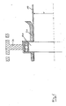
- Figure 1 shows a sectional view of a protective tube 10 according to the invention with the radius r, which is surrounded by a sleeve member 20. Run in the protective tube 10 Lines that are not shown.
- the cuff component 20 is with a mounting device 31 attached to an arm member (not shown) of a robot.
- a ball bearing 40 is arranged, in which the protective tube 10 runs.
- FIG. 2 shows a sectional view of a further embodiment of the present invention, wherein a protective tube 10 is interrupted with the radius r, so that the tube section ends 11 face each other.
- the cuff component 20 surrounds the protective tube 10 and has a ball bearing 40 in which the protective tube 10 is axially rotatable with its Hose section end 11 is mounted.
- a ball bearing 40 in which the protective tube 10 is axially rotatable with its Hose section end 11 is mounted.
- This embodiment is both for attachment suitable on an arm link of a robot, as well as in cooperation with independent additional spaced fastening devices for a protective tube, in which the protective hose is not rotatably supported.
- FIG. 3 shows a sectional view of a further embodiment of the present invention
- a protective tube 10 is interrupted so that the tube section ends 11 are opposite.
- the cuff component 20 surrounds the protective tube 10 and has one Ball bearing 40, in which the protective tube 10 is axially rotatable with its tube section end 11 is stored.
- Ball bearing 40 in which the protective tube 10 is axially rotatable with its tube section end 11 is stored.
- the opposite end of the hose section 11 in a ball bearing 40 which is contained in the sleeve component 20, axially is rotatably mounted.
- the opposite hose section ends 11 are independent axially rotatably supported in the cuff member 20.
- This embodiment is suitable for attachment to an arm link of a robot as well as in interaction with independent additional spaced fasteners for a protective tube in which the protective tube is not rotatably mounted.
- FIG. 4 shows a further embodiment of the protective tube 10 according to the invention, the a region of the interruption that ends from the opposite hose section 11 is formed, is surrounded by a sleeve member 20.
- the Hose section ends 11 are each surrounded by an end sleeve 21.
- the end sleeves 21 are in turn guided within the sleeve component 20 in roller bearings 40 so that the hose section end 11 with the attached end sleeve 21 opposite the cuff component 20 in the roller bearing 40 regardless of the adjacent hose section end with its associated end sleeve 21 can rotate freely axially.
- Both axial deep groove ball bearings and radial ball bearings are suitable, which provide the tensile forces can take up the protective tube.
- a holding device 30 is shown as an option, the assembly of the sleeve component 20, for example on an arm link of an industrial robot serves.
- the holding device 30 has its own rolling bearing 31, in which the Holding device 30 is axially rotatably mounted.
- the holes 32 are used for attachment an arm link of an industrial robot.
- This embodiment is both for attachment suitable on an arm member of a robot, as well as without the fastening device 30 in Interact with independent additional spaced fasteners for a protective tube in which the protective tube is not rotatably mounted.
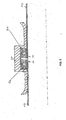
- FIG. 5 shows the end of a protective tube 10 with which it is directed in the direction of the tool, which is carried by an industrial robot, ends and the lines led into it releases which are now continued without a protective tube to be connected to the tool to become.
- the cuff device 20 has a roller bearing 40, which both absorbs axial as well as radial loads, in which the end sleeve 21 is guided axially rotatable becomes.
- the rolling bearings 40 here are e.g. one double-sided or two single-direction thrust ball bearings suitable, but also a radial deep groove ball bearing.
- the end sleeve 21 surrounds this Hose section end 11 of the protective hose 10.
- the cuff component 20 is fixed with a receiving plate for a tool connected, a so-called docking plate 33. Die Lines that are guided in the protective tube 10 can now through the docking plate 33 and out of the protective tube 10.
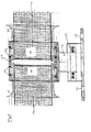
- FIG. 6 shows a schematic overview drawing of a protective hose according to the invention 10 by a return spring (not shown) against the docking plate 33
- Train F is energized.
- the protective tube 10 is through the cuff device 20A in which it is held by the roller bearing 40A so that a movement through the inner cross section of the rolling bearing 40A, which is a ball guide with an outer bush 41A, cage with balls 42A and inner bush 43A and the protective hose 10 leads, possible in the longitudinal direction of the protective tube 10 or the cuff device 20A is.
- a further embodiment provides for the protective tube in the area 10 between the stationary sleeve device 20A, which can be attached to an arm link of an industrial robot is a further cuff device 20B, the protective tube 10 in the Area of an interruption 11, 11 includes.
- the cuff 20B Within the cuff 20B are the opposite Hose section ends 11 held freely rotatable against each other, namely on the one hand in the deep groove ball bearing 40B, on the other hand by connection to the sleeve component 20B.
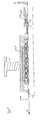
- Figure 7 shows a section of a protective tube according to the invention, namely one Hose section, which is arranged between two sleeve components 20, the Hose section is axially rotatably supported in at least one sleeve component 20.
- One the cuff members 20 can be attached to a docking plate 33 so that the in the Protective hose guided lines after passage through an opening in the docking plate 33 leave the protective hose.
- the protective hose according to the invention has an area in which a subsection of the protective tube 10 an interruption in the longitudinal direction (shown schematically) for example in the form of a linear or spiral Slot.
- This area of the protective tube is covered by sleeves 13, for example so-called protectors partially covered on its circumference, which an opening of the Prevent interruption in the longitudinal direction 12 and also the part of the protective tube 10 with interruption in the longitudinal direction with the circumferentially closed part of the protective tube connect.
- sleeves 13 for example so-called protectors partially covered on its circumference, which an opening of the Prevent interruption in the longitudinal direction 12 and also the part of the protective tube 10 with interruption in the longitudinal direction with the circumferentially closed part of the protective tube connect.
- the circumference is closed with the area of the protective tube, which is an interruption has in the longitudinal direction 12, can each be arranged so that they touch face each other or face each other at a short distance, as long as they are connected by a cuff 13.
Landscapes
- Engineering & Computer Science (AREA)
- General Engineering & Computer Science (AREA)
- Mechanical Engineering (AREA)
- Manipulator (AREA)
- Insulating Bodies (AREA)
- Details Of Indoor Wiring (AREA)
- Rigid Pipes And Flexible Pipes (AREA)
- Protection Of Pipes Against Damage, Friction, And Corrosion (AREA)
Applications Claiming Priority (4)
| Application Number | Priority Date | Filing Date | Title |
|---|---|---|---|
| DE2002120495 DE10220495A1 (de) | 2002-05-07 | 2002-05-07 | Schutzschlauch zur Aufnahme von Leitungen |
| DE10220495 | 2002-05-07 | ||
| DE10231289 | 2002-07-10 | ||
| DE10231289 | 2002-07-10 |
Publications (3)
| Publication Number | Publication Date |
|---|---|
| EP1361384A2 true EP1361384A2 (fr) | 2003-11-12 |
| EP1361384A3 EP1361384A3 (fr) | 2004-01-28 |
| EP1361384B1 EP1361384B1 (fr) | 2005-06-15 |
Family
ID=29251783
Family Applications (1)
| Application Number | Title | Priority Date | Filing Date |
|---|---|---|---|
| EP03010167A Expired - Lifetime EP1361384B1 (fr) | 2002-05-07 | 2003-05-06 | Tuyau flexible de protection pour le logement des conduites |
Country Status (4)
| Country | Link |
|---|---|
| EP (1) | EP1361384B1 (fr) |
| AT (1) | ATE298058T1 (fr) |
| DE (1) | DE50300646D1 (fr) |
| ES (1) | ES2246030T3 (fr) |
Family Cites Families (5)
| Publication number | Priority date | Publication date | Assignee | Title |
|---|---|---|---|---|
| US3239249A (en) * | 1963-04-15 | 1966-03-08 | Youngstown Sheet And Tube Co | Swivel joints |
| DE3434899A1 (de) * | 1983-10-19 | 1985-05-23 | Kuka Schweissanlagen + Roboter Gmbh, 8900 Augsburg | Vorrichtung zum aussenseitigen halten und fuehren von versorgungsleitungen zu bewegten werkzeugen von manipulatoren |
| SE511235C2 (sv) * | 1996-10-14 | 1999-08-30 | Asea Brown Boveri | Anordning och förfarande för att vid en manipulator hålla och föra ett kablage |
| DE19927938A1 (de) * | 1999-06-18 | 2000-12-21 | Wolfgang Suttner | Verdrehbare Kupplung zwischen einem Schlauch und einem Rohr |
| US20020043803A1 (en) * | 2000-08-31 | 2002-04-18 | Kietzmann Michael Clemens | Swivel connector |
-
2003
- 2003-05-06 AT AT03010167T patent/ATE298058T1/de not_active IP Right Cessation
- 2003-05-06 EP EP03010167A patent/EP1361384B1/fr not_active Expired - Lifetime
- 2003-05-06 DE DE50300646T patent/DE50300646D1/de not_active Expired - Fee Related
- 2003-05-06 ES ES03010167T patent/ES2246030T3/es not_active Expired - Lifetime
Also Published As
| Publication number | Publication date |
|---|---|
| EP1361384B1 (fr) | 2005-06-15 |
| ATE298058T1 (de) | 2005-07-15 |
| EP1361384A3 (fr) | 2004-01-28 |
| DE50300646D1 (de) | 2005-07-21 |
| ES2246030T3 (es) | 2006-02-01 |
Similar Documents
| Publication | Publication Date | Title |
|---|---|---|
| DE60034192T2 (de) | Roboter mit Vorrichtungen zum Führen eines Kabels und / oder eines Schlauches | |
| EP2903789B1 (fr) | Robot industriel | |
| EP1369211B1 (fr) | Dispositif de guidage et de rappel d'un conduit flexible de robot | |
| DE3631024C2 (fr) | ||
| DE3111814C2 (fr) | ||
| DE60006165T2 (de) | Industrieroboter | |
| EP0576513B1 (fr) | Manipulateur multiaxe | |
| DE69710444T2 (de) | Vorrichtung zum Laden von Rohren auf Bearbeitungsmaschinen, insbesondere auf Rohrbiegemaschinen | |
| DE102013225630B4 (de) | Industrieroboter | |
| EP2218526B1 (fr) | Procédé et dispositif de fabrication de pièces usinées tubulaires à partir d'un bloc creux pré-percé | |
| DE202006020499U1 (de) | Leitungsführungseinrichtung und Industrieroboter | |
| EP3352950A1 (fr) | Robot industriel | |
| DE102007008985B4 (de) | Haltevorrichtung für eine Energiezuführung | |
| DE102016203361A1 (de) | Industrieroboter mit einer Schutzmanschette | |
| DE69401029T2 (de) | Rohrförmige Führung und Unterstützung | |
| DE2717870C3 (de) | Handhabungsgerät | |
| DE69910132T2 (de) | Lanzenvorrichtung | |
| DE102016008112A1 (de) | Handhabungssystem | |
| EP1361384B1 (fr) | Tuyau flexible de protection pour le logement des conduites | |
| DE10220495A1 (de) | Schutzschlauch zur Aufnahme von Leitungen | |
| EP0621437B1 (fr) | Tuyau de propulsion pour un dispositif d'inspection des tubes | |
| EP3292932B1 (fr) | Ensemble à ressort permettant de générer la force de serrage d'un dispositif de serrage et dispositif de serrage pourvu d'un tel ensemble à ressort | |
| DE102006057496A1 (de) | Pneumatischer Parallelgreifer | |
| DE3546800C2 (de) | Energieversorgungseinrichtung in Teleskopauslegern | |
| DE102023115988A1 (de) | Manipulator für einen Industrieroboter |
Legal Events
| Date | Code | Title | Description |
|---|---|---|---|
| PUAI | Public reference made under article 153(3) epc to a published international application that has entered the european phase |
Free format text: ORIGINAL CODE: 0009012 |
|
| AK | Designated contracting states |
Kind code of ref document: A2 Designated state(s): AT BE BG CH CY CZ DE DK EE ES FI FR GB GR HU IE IT LI LU MC NL PT RO SE SI SK TR |
|
| AX | Request for extension of the european patent |
Extension state: AL LT LV MK |
|
| PUAL | Search report despatched |
Free format text: ORIGINAL CODE: 0009013 |
|
| AK | Designated contracting states |
Kind code of ref document: A3 Designated state(s): AT BE BG CH CY CZ DE DK EE ES FI FR GB GR HU IE IT LI LU MC NL PT RO SE SI SK TR |
|
| AX | Request for extension of the european patent |
Extension state: AL LT LV MK |
|
| RIC1 | Information provided on ipc code assigned before grant |
Ipc: 7B 25J 19/00 B Ipc: 7F 16L 3/26 B Ipc: 7F 16L 27/08 B Ipc: 7F 16L 3/16 A |
|
| 17P | Request for examination filed |
Effective date: 20040615 |
|
| AKX | Designation fees paid |
Designated state(s): AT BE BG CH CY CZ DE DK EE ES FI FR GB GR HU IE IT LI LU MC NL PT RO SE SI SK TR |
|
| GRAP | Despatch of communication of intention to grant a patent |
Free format text: ORIGINAL CODE: EPIDOSNIGR1 |
|
| GRAS | Grant fee paid |
Free format text: ORIGINAL CODE: EPIDOSNIGR3 |
|
| GRAA | (expected) grant |
Free format text: ORIGINAL CODE: 0009210 |
|
| AK | Designated contracting states |
Kind code of ref document: B1 Designated state(s): AT BE BG CH CY CZ DE DK EE ES FI FR GB GR HU IE IT LI LU MC NL PT RO SE SI SK TR |
|
| PG25 | Lapsed in a contracting state [announced via postgrant information from national office to epo] |
Ref country code: CZ Free format text: LAPSE BECAUSE OF FAILURE TO SUBMIT A TRANSLATION OF THE DESCRIPTION OR TO PAY THE FEE WITHIN THE PRESCRIBED TIME-LIMIT Effective date: 20050615 Ref country code: EE Free format text: LAPSE BECAUSE OF FAILURE TO SUBMIT A TRANSLATION OF THE DESCRIPTION OR TO PAY THE FEE WITHIN THE PRESCRIBED TIME-LIMIT Effective date: 20050615 Ref country code: RO Free format text: LAPSE BECAUSE OF FAILURE TO SUBMIT A TRANSLATION OF THE DESCRIPTION OR TO PAY THE FEE WITHIN THE PRESCRIBED TIME-LIMIT Effective date: 20050615 Ref country code: SK Free format text: LAPSE BECAUSE OF FAILURE TO SUBMIT A TRANSLATION OF THE DESCRIPTION OR TO PAY THE FEE WITHIN THE PRESCRIBED TIME-LIMIT Effective date: 20050615 Ref country code: FI Free format text: LAPSE BECAUSE OF FAILURE TO SUBMIT A TRANSLATION OF THE DESCRIPTION OR TO PAY THE FEE WITHIN THE PRESCRIBED TIME-LIMIT Effective date: 20050615 Ref country code: IE Free format text: LAPSE BECAUSE OF FAILURE TO SUBMIT A TRANSLATION OF THE DESCRIPTION OR TO PAY THE FEE WITHIN THE PRESCRIBED TIME-LIMIT Effective date: 20050615 Ref country code: TR Free format text: LAPSE BECAUSE OF FAILURE TO SUBMIT A TRANSLATION OF THE DESCRIPTION OR TO PAY THE FEE WITHIN THE PRESCRIBED TIME-LIMIT Effective date: 20050615 Ref country code: SI Free format text: LAPSE BECAUSE OF FAILURE TO SUBMIT A TRANSLATION OF THE DESCRIPTION OR TO PAY THE FEE WITHIN THE PRESCRIBED TIME-LIMIT Effective date: 20050615 |
|
| REG | Reference to a national code |
Ref country code: GB Ref legal event code: FG4D Free format text: NOT ENGLISH Ref country code: CH Ref legal event code: EP |
|
| REF | Corresponds to: |
Ref document number: 50300646 Country of ref document: DE Date of ref document: 20050721 Kind code of ref document: P |
|
| REG | Reference to a national code |
Ref country code: IE Ref legal event code: FG4D Free format text: LANGUAGE OF EP DOCUMENT: GERMAN |
|
| PG25 | Lapsed in a contracting state [announced via postgrant information from national office to epo] |
Ref country code: GR Free format text: LAPSE BECAUSE OF FAILURE TO SUBMIT A TRANSLATION OF THE DESCRIPTION OR TO PAY THE FEE WITHIN THE PRESCRIBED TIME-LIMIT Effective date: 20050915 Ref country code: BG Free format text: LAPSE BECAUSE OF FAILURE TO SUBMIT A TRANSLATION OF THE DESCRIPTION OR TO PAY THE FEE WITHIN THE PRESCRIBED TIME-LIMIT Effective date: 20050915 Ref country code: DK Free format text: LAPSE BECAUSE OF FAILURE TO SUBMIT A TRANSLATION OF THE DESCRIPTION OR TO PAY THE FEE WITHIN THE PRESCRIBED TIME-LIMIT Effective date: 20050915 Ref country code: SE Free format text: LAPSE BECAUSE OF FAILURE TO SUBMIT A TRANSLATION OF THE DESCRIPTION OR TO PAY THE FEE WITHIN THE PRESCRIBED TIME-LIMIT Effective date: 20050915 |
|
| GBT | Gb: translation of ep patent filed (gb section 77(6)(a)/1977) |
Effective date: 20050923 |
|
| PG25 | Lapsed in a contracting state [announced via postgrant information from national office to epo] |
Ref country code: PT Free format text: LAPSE BECAUSE OF FAILURE TO SUBMIT A TRANSLATION OF THE DESCRIPTION OR TO PAY THE FEE WITHIN THE PRESCRIBED TIME-LIMIT Effective date: 20051124 |
|
| PG25 | Lapsed in a contracting state [announced via postgrant information from national office to epo] |
Ref country code: HU Free format text: LAPSE BECAUSE OF FAILURE TO SUBMIT A TRANSLATION OF THE DESCRIPTION OR TO PAY THE FEE WITHIN THE PRESCRIBED TIME-LIMIT Effective date: 20051216 |
|
| REG | Reference to a national code |
Ref country code: IE Ref legal event code: FD4D |
|
| REG | Reference to a national code |
Ref country code: ES Ref legal event code: FG2A Ref document number: 2246030 Country of ref document: ES Kind code of ref document: T3 |
|
| PLBI | Opposition filed |
Free format text: ORIGINAL CODE: 0009260 |
|
| ET | Fr: translation filed | ||
| 26 | Opposition filed |
Opponent name: PMA AG Effective date: 20060311 |
|
| PG25 | Lapsed in a contracting state [announced via postgrant information from national office to epo] |
Ref country code: AT Free format text: LAPSE BECAUSE OF NON-PAYMENT OF DUE FEES Effective date: 20060506 |
|
| PLAX | Notice of opposition and request to file observation + time limit sent |
Free format text: ORIGINAL CODE: EPIDOSNOBS2 |
|
| PG25 | Lapsed in a contracting state [announced via postgrant information from national office to epo] |
Ref country code: ES Free format text: LAPSE BECAUSE OF NON-PAYMENT OF DUE FEES Effective date: 20060508 |
|
| PG25 | Lapsed in a contracting state [announced via postgrant information from national office to epo] |
Ref country code: MC Free format text: LAPSE BECAUSE OF NON-PAYMENT OF DUE FEES Effective date: 20060531 Ref country code: BE Free format text: LAPSE BECAUSE OF NON-PAYMENT OF DUE FEES Effective date: 20060531 |
|
| PGFP | Annual fee paid to national office [announced via postgrant information from national office to epo] |
Ref country code: IT Payment date: 20060531 Year of fee payment: 4 |
|
| NLR1 | Nl: opposition has been filed with the epo |
Opponent name: PMA AG |
|
| REG | Reference to a national code |
Ref country code: FR Ref legal event code: ST Effective date: 20070131 |
|
| REG | Reference to a national code |
Ref country code: ES Ref legal event code: FD2A Effective date: 20060508 |
|
| BERE | Be: lapsed |
Owner name: *DELECTRIC ELEKTROBEDARF G.M.B.H. & CO. K.G. Effective date: 20060531 |
|
| REG | Reference to a national code |
Ref country code: CH Ref legal event code: PL |
|
| GBPC | Gb: european patent ceased through non-payment of renewal fee |
Effective date: 20070506 |
|
| PG25 | Lapsed in a contracting state [announced via postgrant information from national office to epo] |
Ref country code: NL Free format text: LAPSE BECAUSE OF NON-PAYMENT OF DUE FEES Effective date: 20071201 |
|
| NLV4 | Nl: lapsed or anulled due to non-payment of the annual fee |
Effective date: 20071201 |
|
| PG25 | Lapsed in a contracting state [announced via postgrant information from national office to epo] |
Ref country code: LI Free format text: LAPSE BECAUSE OF NON-PAYMENT OF DUE FEES Effective date: 20070531 Ref country code: CH Free format text: LAPSE BECAUSE OF NON-PAYMENT OF DUE FEES Effective date: 20070531 |
|
| PG25 | Lapsed in a contracting state [announced via postgrant information from national office to epo] |
Ref country code: FR Free format text: LAPSE BECAUSE OF NON-PAYMENT OF DUE FEES Effective date: 20060531 |
|
| PG25 | Lapsed in a contracting state [announced via postgrant information from national office to epo] |
Ref country code: GB Free format text: LAPSE BECAUSE OF NON-PAYMENT OF DUE FEES Effective date: 20070506 |
|
| PG25 | Lapsed in a contracting state [announced via postgrant information from national office to epo] |
Ref country code: LU Free format text: LAPSE BECAUSE OF NON-PAYMENT OF DUE FEES Effective date: 20060506 |
|
| PG25 | Lapsed in a contracting state [announced via postgrant information from national office to epo] |
Ref country code: CY Free format text: LAPSE BECAUSE OF FAILURE TO SUBMIT A TRANSLATION OF THE DESCRIPTION OR TO PAY THE FEE WITHIN THE PRESCRIBED TIME-LIMIT Effective date: 20050615 |
|
| PG25 | Lapsed in a contracting state [announced via postgrant information from national office to epo] |
Ref country code: DE Free format text: LAPSE BECAUSE OF NON-PAYMENT OF DUE FEES Effective date: 20061201 |
|
| PLAM | Termination of opposition procedure: information related to despatch of decision modified |
Free format text: ORIGINAL CODE: EPIDOSCOPC1 |
|
| PLBD | Termination of opposition procedure: decision despatched |
Free format text: ORIGINAL CODE: EPIDOSNOPC1 |
|
| PG25 | Lapsed in a contracting state [announced via postgrant information from national office to epo] |
Ref country code: IT Free format text: LAPSE BECAUSE OF NON-PAYMENT OF DUE FEES Effective date: 20070506 |
|
| PLAU | Termination of opposition procedure: information related to despatch of decision deleted |
Free format text: ORIGINAL CODE: EPIDOSDOPC1 |
|
| PLBD | Termination of opposition procedure: decision despatched |
Free format text: ORIGINAL CODE: EPIDOSNOPC1 |
|
| PUAJ | Public notification under rule 129 epc |
Free format text: ORIGINAL CODE: 0009425 |
|
| 32PN | Public notification |
Free format text: ENTSCHEIDUNG UEBER DIE EINSTELLUNG DES EINSPRUCHSVERFAHRENS, EPA FORM 2352 VOM 29.01.10 |
|
| PLBM | Termination of opposition procedure: date of legal effect published |
Free format text: ORIGINAL CODE: 0009276 |
|
| STAA | Information on the status of an ep patent application or granted ep patent |
Free format text: STATUS: OPPOSITION PROCEDURE CLOSED |
|
| 27C | Opposition proceedings terminated |
Effective date: 20100521 |