EP1361374A1 - Kupplungseinrichtung für ein Kraftfahrzeug oder dergleichen - Google Patents
Kupplungseinrichtung für ein Kraftfahrzeug oder dergleichen Download PDFInfo
- Publication number
- EP1361374A1 EP1361374A1 EP02010541A EP02010541A EP1361374A1 EP 1361374 A1 EP1361374 A1 EP 1361374A1 EP 02010541 A EP02010541 A EP 02010541A EP 02010541 A EP02010541 A EP 02010541A EP 1361374 A1 EP1361374 A1 EP 1361374A1
- Authority
- EP
- European Patent Office
- Prior art keywords
- piston
- pressure
- housing
- clutch
- essentially
- Prior art date
- Legal status (The legal status is an assumption and is not a legal conclusion. Google has not performed a legal analysis and makes no representation as to the accuracy of the status listed.)
- Granted
Links
- 238000006073 displacement reaction Methods 0.000 claims abstract description 14
- 230000008878 coupling Effects 0.000 claims description 18
- 238000010168 coupling process Methods 0.000 claims description 18
- 238000005859 coupling reaction Methods 0.000 claims description 18
- 230000033001 locomotion Effects 0.000 description 6
- 238000007789 sealing Methods 0.000 description 6
- 238000005516 engineering process Methods 0.000 description 5
- 239000000969 carrier Substances 0.000 description 4
- 238000001816 cooling Methods 0.000 description 4
- 241000446313 Lamella Species 0.000 description 3
- 238000004519 manufacturing process Methods 0.000 description 3
- 238000002485 combustion reaction Methods 0.000 description 1
- 239000002826 coolant Substances 0.000 description 1
- 238000011161 development Methods 0.000 description 1
- 230000018109 developmental process Effects 0.000 description 1
- 239000012467 final product Substances 0.000 description 1
- 230000007246 mechanism Effects 0.000 description 1
- 238000000034 method Methods 0.000 description 1
- 230000000149 penetrating effect Effects 0.000 description 1
- 238000007639 printing Methods 0.000 description 1
Images



Classifications
-
- F—MECHANICAL ENGINEERING; LIGHTING; HEATING; WEAPONS; BLASTING
- F16—ENGINEERING ELEMENTS AND UNITS; GENERAL MEASURES FOR PRODUCING AND MAINTAINING EFFECTIVE FUNCTIONING OF MACHINES OR INSTALLATIONS; THERMAL INSULATION IN GENERAL
- F16D—COUPLINGS FOR TRANSMITTING ROTATION; CLUTCHES; BRAKES
- F16D25/00—Fluid-actuated clutches
- F16D25/06—Fluid-actuated clutches in which the fluid actuates a piston incorporated in, i.e. rotating with the clutch
- F16D25/062—Fluid-actuated clutches in which the fluid actuates a piston incorporated in, i.e. rotating with the clutch the clutch having friction surfaces
- F16D25/063—Fluid-actuated clutches in which the fluid actuates a piston incorporated in, i.e. rotating with the clutch the clutch having friction surfaces with clutch members exclusively moving axially
- F16D25/0635—Fluid-actuated clutches in which the fluid actuates a piston incorporated in, i.e. rotating with the clutch the clutch having friction surfaces with clutch members exclusively moving axially with flat friction surfaces, e.g. discs
- F16D25/0638—Fluid-actuated clutches in which the fluid actuates a piston incorporated in, i.e. rotating with the clutch the clutch having friction surfaces with clutch members exclusively moving axially with flat friction surfaces, e.g. discs with more than two discs, e.g. multiple lamellae
-
- F—MECHANICAL ENGINEERING; LIGHTING; HEATING; WEAPONS; BLASTING
- F16—ENGINEERING ELEMENTS AND UNITS; GENERAL MEASURES FOR PRODUCING AND MAINTAINING EFFECTIVE FUNCTIONING OF MACHINES OR INSTALLATIONS; THERMAL INSULATION IN GENERAL
- F16D—COUPLINGS FOR TRANSMITTING ROTATION; CLUTCHES; BRAKES
- F16D25/00—Fluid-actuated clutches
- F16D25/12—Details not specific to one of the before-mentioned types
Definitions
- the invention relates to a coupling device for a Motor vehicle or the like according to the preamble of Claim 1.
- Such coupling devices include next to the actual clutch, i.e. the drive side a drive shaft, for example with an internal combustion engine and on the output side via an output shaft, for example with a gear connected elements, which in the case of a Actuating the clutch, the input shaft with the output shaft connect, an actuator for actuation this clutch.
- the actual clutch i.e. the drive side a drive shaft, for example with an internal combustion engine and on the output side via an output shaft, for example with a gear connected elements, which in the case of a Actuating the clutch, the input shaft with the output shaft connect, an actuator for actuation this clutch.
- the invention now relates to coupling devices in which the actuator essentially consists of one There is a pressure piston.
- This pressure piston is according to the state the technology arranged in a housing.
- This pressure piston is also slidably guided in the housing. By a corresponding displacement movement of the pressure piston can Clutch are operated.
- a device for generating a counter to the aforementioned compressive force acting counter pressure A includes such a device for generating the back pressure force another piston, which is subsequently used as a compensating piston is designated.
- This compensation piston is like this arranged that he with the plunger and with the housing a cavity, which is subsequently used as a compensation chamber is included.
- This compensation chamber can Generation of the counter pressure force - similar to the aforementioned Pressure chamber with a (counter) pressure medium, preferably a synthetic oil.
- the multi-plate clutch device shown comprises a the drive side 22 with a (not shown) Drive shaft connected essentially rotationally symmetrical to an axis ax formed housing consisting of an im essential hollow cylindrical outer disk carrier 5 and one essentially to the one essentially hollow cylindrical Outer disk carrier 5 coaxial inner hollow cylindrical Middle part 15.4.
- Part of the multi-plate clutch device is also a on the output side 23 with a (not shown) output shaft connected essentially Inner disk carrier designed to be rotationally symmetrical to the axis ax 7th
- Outer and inner disk carriers 5, 7 are - as from their Deriving the name is the bearer of so-called outside and Inner slats 6, 8. These are on their respective outer or Inner disk carriers 5, 7 essentially non-rotatably axially displaceable.
- the whole arrangement consisting of three outer and three in the present case Inner plates 5, 7 are referred to as plate pack 4.
- foreign and Inner slats 5, 7 intermesh like a comb and are each in pairs can be brought into frictional connection.
- the one at the end of the plate pack 4 and through a locking ring 27 in its one-sided axial displacement limited slat (here an outer slat) is called the end plate.
- the end plate is in the Drawing figure 4 provided with the reference number 9.
- This pressure plate is in the drawing figure 4 with provided with the reference number 10.
- This arrangement is one of several - in the present case six slats - preferably using a via a cooling oil space 13 supplied coolant such.
- B. cooling oil 26, cooled plate pack 4 on outer and inner plate carriers 5, 7 forms the previous clutch designated part of a multi-plate clutch device.
- the pressure piston 1 is essentially ring-shaped. It is with its inner wall on the outer wall of the im essential cylindrical jacket-shaped middle part 15.4 displaceable guided. With a corresponding shifting movement of the pressure piston 1 presses it by means of a corresponding ring-shaped in the present case Pressure element 14 against the pressure plate 10 of the plate pack 4, so this due to the lack of axial Option to escape the Enplatte 9 is compressed and the individual adjacent slats 6, 8 in frictional connection kick, so the clutch is actuated.
- the housing and the pressure piston 1 form a cavity arranged to each other.
- This cavity, the so-called Pressure chamber, which is present in relation to the environment is sealed by means of two sealing rings 20, 21 is in the Drawing figure marked with the reference numeral 11.
- this pressure chamber 11 is pressure oil 24 feedable.
- the corresponding openings are therefore also referred to as pressure oil channels.
- One of these pressure oil channels is the drawing figure 4 and by the reference numeral 17 marked.
- the above as part of the actuator specified compensation piston 2 is in the embodiment according to 4 is essentially annular. He is like that arranged that he with the pressure piston 1 and with the Middle part 15.4 of the housing encloses a cavity. This cavity is called the compensation chamber and is identified in FIG. 4 by reference number 12.
- the compensation chamber 12 can be used to generate the aforementioned Back pressure force similar to the pressure chamber 11 described above with a (counter) fed through corresponding openings Pressure medium, hereinafter referred to as compensating oil 25, be charged.
- the openings for feeding the Compensation oil 25 are hereinafter referred to as compensation oil channels designated.
- One of these the middle part 15.4 of the housing Radially penetrating compensation oil channels is shown in FIG. 4 shown and identified by reference 18.4.
- a spring assembly 3rd arranged, which against an inner wall of the compensating piston 2 supported against the direction of displacement of the Pressure piston 1 when actuating the clutch against the Pressure piston 1 is held.
- the invention is therefore based on the object, the known To design and further develop coupling devices in such a way that these are cheaper to manufacture and moreover have smaller dimensions.
- This task is made generic by a coupling device kind with the characteristics of the characteristic part of the Claim 1 solved according to the invention.
- the essential idea of the invention is that for essentially immovable when operating the clutch Hold the balance piston on the housing Locking or snap device is provided.
- a locking or snap device is a Compensating piston can be installed quickly and easily.
- latching or snap-in devices from a variety other applications known, so an inexpensive Manufacturing and space-saving execution is guaranteed.
- the locking or snap device hereinafter the For the sake of simplicity, only referred to as a latching device, comprises at least one locking element of the first type, which the Housing is assigned and at least one locking element second Type, which is assigned to the compensating piston, the Latching elements of the first and second type with each other in latching or Snap action are transferable.
- This variant represents the simplest form of a snap or snap closure and is therefore compared to complicated rotary snap or screw snap mechanisms, which of course is also conceivable are to be preferred.
- the Invention before that the locking element of the second kind part of the compensating piston is part a separate compensation piston holding device, which may be provided for this purpose is. Both versions can combined if necessary. In all In cases there is a solution to the problem presented.
- the housing in essentially rotationally symmetrical to an axis is and a substantially cylindrical jacket-shaped central part includes on the outer wall of the pressure piston, which in is essentially annular, with its Inner wall is axially displaceable and on which the Compensating piston, which is also essentially ring-shaped is formed when actuating the clutch in the axial
- the locking element first type one in the inner wall or the outer wall of the Middle part is essentially coaxial circumferential groove and that Detent element of the second type comprises at least one detent, which can be engaged in the circumferential groove for locking.
- the at least one latching lug is preferably at the end of one from the compensating piston or from the compensating piston holding device essentially axially protruding fingers formed. Usually a lot of these end up of a finger attached locking lugs coaxially on one annular end of the compensating piston or the compensating piston holding device appropriate. Alternatively, is according to the invention also provided that a single latch is coaxial circumferential.
- the compensating piston holding device is preferably ring-shaped suitable for a compensation piston similar to that according to the Figure 4 is formed.
- All multi-plate clutch devices on which below Reference is made to include one on the drive side 22 a (not shown) drive shaft connected in essentially rotationally symmetrical to an axis ax trained housing consisting of an essentially hollow cylindrical outer disk carrier 5 and one in essentially to the one essentially hollow cylindrical Outer disk carrier 5 coaxial inner hollow cylindrical Middle part, which in the respective figures to the different exemplary embodiments according to the invention its inventive design with different Reference numerals 15.1 to 15.3 is provided.
- each Plate pack 4 is provided, which on the outer or Inner disk carriers 5, 7 essentially non-rotatably but axially have limited mobility.
- the pressure piston 1 is in all embodiments according to the invention ( Figures 1 to 3) furthermore an annular formed pressure element 14 for actuating the clutch assigned.
- the pressure piston 1 is with its inner wall on the Outer wall of the substantially cylindrical jacket Middle part 15.1, 15.2, 15.3 slidably guided.
- the housing and the pressure piston 1 are the so-called pressure chamber 11 arranged to form each other.
- This pressure chamber 11 is to the environment by means of two sealing rings 20, 21 sealed. Furthermore, one can see from the drawing figures 1 to 3 one identified by reference numeral 17 Pressure oil channel in the middle part 15.1, 15.2, 15.3.
- the compensation piston 2 is in all embodiments according to Figures 1 to 3 substantially annular trained and arranged so that it matches the respective Pressure piston 1 and with the respective middle part 15.1, 15.2, 15.3 of the housing, the so-called compensation chamber 12 includes. Between the adjacent ones Walls of the pressure piston 1 and the compensating piston 2 is a sealing lip 19 for sealing the compensation chamber 12 provided to the environment.
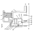
- FIGS 1a) and 1b) now show a first embodiment a coupling device for a motor vehicle with locking device provided according to the invention.
- the latching device realized in that the substantially circular Compensating piston 2 with individual - here: six - on the inner circumference -Here equidistant to each other- and essentially in the axial direction fingers 30.1 is provided, which on the free ends of which each point radially outward Have latch 31.1 in the manner of a barb.
- the middle part 15.1 has one in the cylindrical inner wall screwed in coaxial circumferential a radially inward facing coaxial circumferential Latch 29.1 forming groove 28.1, in which the to Ends of the fingers 30.1 arranged locking lugs 31.1 of the Compensating piston 2 for locking the compensating piston with the housing can be engaged. It should be noted that the spaces between the individual fingers 30.1 now serve as leveling oil channels 18.1 for leveling oil 25.
- Figures 2 shows a second embodiment of a Coupling device for a motor vehicle with the invention provided locking device.
- the locking device realized in that the substantially circular Compensating piston 2 with individual arranged on the outer circumference and fingers pointing essentially in the axial direction 30.2 is provided, which is radial at its free ends inward-facing latch 31.2 in the manner of a barb exhibit.
- the middle part 15.2 a screwed into the cylindrical outer wall coaxial, one radially facing coaxial circumferential locking lug 29.2 forming groove 28.2.
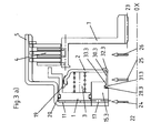
- Figures 3a) and 3b) show a third embodiment a coupling device for a motor vehicle with locking device provided according to the invention.
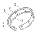
- the latching device realized in that for the substantially circular Compensating piston 2 a special cylindrical Retaining ring 32.3 is provided.
- This retaining ring 32.3 embraces on one side the compensating piston 2 on its inner circumference.
- this retaining ring 32.3 is similar to that Compensating piston 2 described above essentially in Axial direction ax extending fingers 30.3, which here according to the first embodiment according to the figures 1a) and 1b) end in a latch 31.3.
Landscapes
- Engineering & Computer Science (AREA)
- General Engineering & Computer Science (AREA)
- Mechanical Engineering (AREA)
- Hydraulic Clutches, Magnetic Clutches, Fluid Clutches, And Fluid Joints (AREA)
Abstract
Description
- Figur 1a) -
- ein erstes Ausführungsbeispiel einer erfindungsgemäßen Lamellenkupplungseinrichtung mit erfindungsgemäßem Ausgleichskolben im Axialhalbschnitt
- Figur 1b) -
- den erfindungsgemäßen Ausgleichskolben gemäß der Figur 1a) in perspektivischer Darstellung
- Figur 2 -
- ein zweites Ausführungsbeispiel einer erfindungsgemäßen Lamellenkupplungseinrichtung mit erfindungsgemäßem Ausgleichskolben im Axialhalbschnitt
- Figur 3a) -
- ein drittes Ausführungsbeispiel einer erfindungsgemäßen Lamellenkupplungseinrichtung mit erfindungsgemäßem Haltering für den Ausgleichskolben im Axialhalbschnitt
- Figur 3b) -
- den erfindungsgemäßen Haltering gemäß der Figur 3a) in perspektivischer Darstellung
- Figur 4 -
- ein Ausführungsbeispiel einer Lamellenkupplungseinrichtung gemäß dem Stand der Technik im Axialhalbschnitt
- 1
- Druckkolben
- 2
- Ausgleichskolben
- 3
- Federpaket
- 4
- Lamellenpaket
- 5
- Außenlamellenträger
- 6
- Außenlamelle
- 7
- Innenlamellenträger
- 8
- Innenlamelle
- 9
- Endplatte
- 10
- Druckplatte
- 11
- Druckkammer
- 12
- Ausgleichskammer
- 13
- Kühlölraum
- 14
- Druckelement
- 15.1
- Mittelteil
- 15.2
- Mittelteil
- 15.3
- Mittelteil
- 15.4
- Mittelteil
- 16.4
- Sicherungsring
- 17
- Druckölkanal
- 18.1
- Ausgleichsölkanal
- 18.2
- Ausgleichsölkanal
- 18.3
- Ausgleichsölkanal
- 18.4
- Ausgleichsölkanal
- 19
- Dichtlippe
- 20
- Dichtring
- 21
- Dichtring
- 22
- Antriebsseite
- 23
- Abtriebsseite
- 24
- Drucköl
- 25
- Ausgleichsöl
- 26
- Kühlöl
- 27
- Sicherungsring
- 28.1
- umlaufende Nut
- 28.2
- umlaufende Nut
- 28.3
- umlaufende Nut
- 29.1
- umlaufende Rastnase
- 29.2
- umlaufende Rastnase
- 29.3
- umlaufende Rastnase
- 30.1
- Finger
- 30.2
- Finger
- 30.3
- Finger
- 31.1
- Rastnase
- 31.2
- Rastnase
- 31.3
- Rastnase
- 32.3
- Haltering
- ax
- Achse
Claims (10)
- Kupplungseinrichtung, insbesondere Lamellenkupplungseinrichtung,dadurch gekennzeichnet, dassmit einem Druckkolben (1) zum Erzeugen einer Druckkraft zum Betätigen einer Kupplung (4, 9, 8, 10, 27), wobei der Druckkolben (1) in einem Gehäuse (5, 15.1, 15.2, 15.3, 15.4) verschieblich geführt ist, wobei das Gehäuse (5, 15.1, 15.2, 15.3, 15.4) und der Druckkolben (1) eine Druckkammer (11) einschließen, welche zum Erzeugen der Druckkraft mit einem Druckmittel (24) beaufschlagbar ist, undmit einem Ausgleichskolben (2) zum Erzeugen einer Gegendruckkraft auf den Druckkolben (1), wobei der Ausgleichskolben (2) an dem Gehäuse (5, 15.1, 15.2, 15.3, 15.4) beim Betätigen der Kupplung (4, 9, 8, 10, 27) in Verschieberichtung des Druckkolbens (1) im wesentlichen unverschieblich gehalten ist, wobei das Gehäuse (5, 15.1, 15.2, 15.3, 15.4), der Druckkolben (1) und der Ausgleichskolben (2) eine Ausgleichskammer (12) einschließen, welche zum Erzeugen der Gegendruckkraft mit einem Gegendruckmittel beaufschlagbar ist
zum beim Betätigen der Kupplung (4, 9, 8, 10, 27) im wesentlichen unverschieblichen Halten des Ausgleichskolbens (2) an dem Gehäuse (5, 15.1, 15.2, 15.3, 15.4) in Verschieberichtung des Druckkolbens (1) eine Rasteinrichtung (28.1, 28.2, 28.3, 29.1, 29.2, 29.3, 30.1, 30.2, 30.3, 31.1, 31.2, 31.3) vorgesehen ist. - Kupplungseinrichtung nach Anspruch 1, dadurch gekennzeichnet, dass die Rasteinrichtung wenigstens ein Rastelement erster Art (28.1, 28.2, 28.3, 29.1, 29.2, 29.3) umfaßt, welches dem Gehäuse (5, 15.1, 15.2, 15.3) zugeordnet ist und wenigstens ein Rastelement zweiter Art (31.1, 31.2, 31.3), welches dem Ausgleichskolben (2) zugeordnet ist, wobei die Rastelemente erster und zweiter Art (28.1, 28.2, 28.3, 29.1, 29.2, 29.3, 31.1, 31.2, 31.3) miteinander in Rasteingriff verbringbar sind.
- Kupplungseinrichtung nach Anspruch 2, dadurch gekennzeichnet, dass das Rastelement zweiter Art (31.1, 31.2) Bestandteil des Ausgleichskolbens (2) ist.
- Kupplungseinrichtung nach Anspruch 2, dadurch gekennzeichnet, dass das Rastelement zweiter Art (31.3) Bestandteil einer Ausgleichskolbenhalteeinrichtung (32.3) ist.
- Kupplungseinrichtung nach einem der vorangegangenen Ansprüche, bei der das Gehäuse (5, 15.1, 15.2, 15.3) im wesentlichen rotationssymmetrisch zu einer Achse (ax) ausgebildet ist und ein im wesentlichen zylindermantelförmiges Mittelteil ((15.1, 15.2, 15.3) umfaßt an dessen Außenwandung der Druckkolben (1), welcher im wesentlichen ringförmig ausgebildet ist, mit dessen Innenwandung axial verschieblich geführt ist und an dem der Ausgleichskolben (2), welcher im wesentlichen ringförmig ausgebildet ist, beim Betätigen der Kupplung (4, 9, 8, 10, 27) in axialer Verschieberichtung des Druckkolbens (1) unverschieblich gehalten ist, , dadurch gekennzeichnet, dass das Rastelement erster Art eine in der Innenwandung oder der Außenwandung des Mittelteils (15.1, 15.2, 15.3) im wesentlichen koaxial umlaufende Nut (28.1, 28.2, 28.3) ist und das Rastelement zweiter Art wenigstens eine Rastnase (29.1, 29.2, 29.3) umfaßt, welche zum Verrasten in die umlaufende Nut (28.1, 28.2, 28.3) eingreifbar ist.
- Kupplungseinrichtung nach Anspruch 5, dadurch gekennzeichnet, dass die wenigstens eine Rastnase (31.1, 31.2) am Ende eines von dem Ausgleichskolben (1) oder von der Ausgleichskolbenhalteeinrichtung (32.3) im wesentlichen axial abstehenden Fingers (30.1, 30.2, 30.3) angeformt ist.
- Kupplungseinrichtung nach einem der Ansprüche 5 oder 6, dadurch gekennzeichnet, dass die Rastnase (31.3) koaxial umlaufend ausgebildet ist.
- Kupplungseinrichtung nach einem der Ansprüche 5, 6 oder 7, dadurch gekennzeichnet, dass die Ausgleichskolbenhalteeinrichtung (32.3) ringförmig ausgebildet ist.
- Ausgleichskolben (2) für eine Kupplungseinrichtung nach einem der vorangegangenen Ansprüche.
- Ausgleichskolbenhalteeinrichtung (32.3) für eine Kupplungseinrichtung nach einem der vorangegangenen Ansprüche.
Priority Applications (6)
| Application Number | Priority Date | Filing Date | Title |
|---|---|---|---|
| EP02010541A EP1361374B1 (de) | 2002-05-10 | 2002-05-10 | Kupplungseinrichtung für ein Kraftfahrzeug oder dergleichen |
| DE50213287T DE50213287D1 (de) | 2002-05-10 | 2002-05-10 | Kupplungseinrichtung für ein Kraftfahrzeug oder dergleichen |
| KR10-2003-0022155A KR20030087529A (ko) | 2002-05-10 | 2003-04-09 | 자동차 등을 위한 클러치 장치 |
| US10/428,545 US6935481B2 (en) | 2002-05-10 | 2003-05-02 | Snap-in balance piston |
| JP2003128588A JP4373124B2 (ja) | 2002-05-10 | 2003-05-07 | クラッチ装置 |
| JP2009160387A JP5084792B2 (ja) | 2002-05-10 | 2009-07-07 | クラッチ装置 |
Applications Claiming Priority (1)
| Application Number | Priority Date | Filing Date | Title |
|---|---|---|---|
| EP02010541A EP1361374B1 (de) | 2002-05-10 | 2002-05-10 | Kupplungseinrichtung für ein Kraftfahrzeug oder dergleichen |
Publications (2)
| Publication Number | Publication Date |
|---|---|
| EP1361374A1 true EP1361374A1 (de) | 2003-11-12 |
| EP1361374B1 EP1361374B1 (de) | 2009-02-18 |
Family
ID=29225638
Family Applications (1)
| Application Number | Title | Priority Date | Filing Date |
|---|---|---|---|
| EP02010541A Expired - Lifetime EP1361374B1 (de) | 2002-05-10 | 2002-05-10 | Kupplungseinrichtung für ein Kraftfahrzeug oder dergleichen |
Country Status (5)
| Country | Link |
|---|---|
| US (1) | US6935481B2 (de) |
| EP (1) | EP1361374B1 (de) |
| JP (2) | JP4373124B2 (de) |
| KR (1) | KR20030087529A (de) |
| DE (1) | DE50213287D1 (de) |
Cited By (2)
| Publication number | Priority date | Publication date | Assignee | Title |
|---|---|---|---|---|
| DE102018201782A1 (de) | 2018-02-06 | 2019-08-08 | Zf Friedrichshafen Ag | Kupplungsanordnung |
| DE102018201781A1 (de) | 2018-02-06 | 2019-08-08 | Zf Friedrichshafen Ag | Kupplungsvorrichtung |
Families Citing this family (7)
| Publication number | Priority date | Publication date | Assignee | Title |
|---|---|---|---|---|
| GB0508275D0 (en) * | 2005-04-25 | 2005-06-01 | Visual Edge Ltd | Fastening system |
| DE102006057915A1 (de) | 2006-10-11 | 2008-05-15 | Borg Warner Inc., Auburn Hills | Kupplung und Kupplungsanordnung mit einer solchen Kupplung |
| US9464808B2 (en) * | 2008-11-05 | 2016-10-11 | Parker-Hannifin Corporation | Nozzle tip assembly with secondary retention device |
| US8453819B2 (en) | 2010-02-22 | 2013-06-04 | Twin Disc, Inc. | Balanced clutch system |
| KR102089482B1 (ko) * | 2018-06-27 | 2020-04-23 | 평화오일씰공업 주식회사 | 자동변속기용 클러치 유니트 |
| US11512747B2 (en) * | 2020-01-09 | 2022-11-29 | Cnh Industrial America Llc | Balanced piston clutch |
| DE102020128743B4 (de) | 2020-07-22 | 2024-02-22 | Schaeffler Technologies AG & Co. KG | Kupplungseinrichtung |
Citations (3)
| Publication number | Priority date | Publication date | Assignee | Title |
|---|---|---|---|---|
| JPH04191530A (ja) * | 1990-11-21 | 1992-07-09 | Nissan Motor Co Ltd | 湿式多板クラッチ装置 |
| US5267807A (en) * | 1990-11-09 | 1993-12-07 | Ford Motor Company | Driveable connection between drum components for automatic transmission friction disc clutch |
| EP1079130A2 (de) * | 1999-08-24 | 2001-02-28 | BorgWarner Inc. | Automatisches Getriebe mit gehäusefester Kupplung und gezielter Kühlung |
Family Cites Families (9)
| Publication number | Priority date | Publication date | Assignee | Title |
|---|---|---|---|---|
| JPS54163257U (de) * | 1978-05-08 | 1979-11-15 | ||
| JPS5682313U (de) * | 1979-11-30 | 1981-07-03 | ||
| US4813808A (en) * | 1983-08-19 | 1989-03-21 | Gkn Automotive Components Inc. | Axial retaining member and method for interconnecting male and female splined members |
| JP2832440B2 (ja) * | 1988-11-04 | 1998-12-09 | アイシン・エィ・ダブリュ株式会社 | 自動変速機のクラツチの配設構造 |
| US4898493A (en) * | 1989-03-16 | 1990-02-06 | Karl Blankenburg | Method and apparatus for assembling parts |
| US5048656A (en) * | 1990-08-29 | 1991-09-17 | Eaton Corporation | Fluid operated clutch control system having latch member |
| US5172799A (en) * | 1991-02-08 | 1992-12-22 | Toyota Jidosha Kabushiki Kaisha | Centrifugal hydraulic cancel mechanism for the rotating clutch |
| JP2768133B2 (ja) * | 1992-05-18 | 1998-06-25 | 三菱自動車工業株式会社 | 流体圧クラッチ装置 |
| JP6003229B2 (ja) * | 2012-05-24 | 2016-10-05 | コベルコ建機株式会社 | 建設機械のブーム駆動装置 |
-
2002
- 2002-05-10 EP EP02010541A patent/EP1361374B1/de not_active Expired - Lifetime
- 2002-05-10 DE DE50213287T patent/DE50213287D1/de not_active Expired - Lifetime
-
2003
- 2003-04-09 KR KR10-2003-0022155A patent/KR20030087529A/ko not_active Ceased
- 2003-05-02 US US10/428,545 patent/US6935481B2/en not_active Expired - Fee Related
- 2003-05-07 JP JP2003128588A patent/JP4373124B2/ja not_active Expired - Fee Related
-
2009
- 2009-07-07 JP JP2009160387A patent/JP5084792B2/ja not_active Expired - Fee Related
Patent Citations (3)
| Publication number | Priority date | Publication date | Assignee | Title |
|---|---|---|---|---|
| US5267807A (en) * | 1990-11-09 | 1993-12-07 | Ford Motor Company | Driveable connection between drum components for automatic transmission friction disc clutch |
| JPH04191530A (ja) * | 1990-11-21 | 1992-07-09 | Nissan Motor Co Ltd | 湿式多板クラッチ装置 |
| EP1079130A2 (de) * | 1999-08-24 | 2001-02-28 | BorgWarner Inc. | Automatisches Getriebe mit gehäusefester Kupplung und gezielter Kühlung |
Non-Patent Citations (1)
| Title |
|---|
| PATENT ABSTRACTS OF JAPAN vol. 016, no. 519 (M - 1330) 26 October 1992 (1992-10-26) * |
Cited By (2)
| Publication number | Priority date | Publication date | Assignee | Title |
|---|---|---|---|---|
| DE102018201782A1 (de) | 2018-02-06 | 2019-08-08 | Zf Friedrichshafen Ag | Kupplungsanordnung |
| DE102018201781A1 (de) | 2018-02-06 | 2019-08-08 | Zf Friedrichshafen Ag | Kupplungsvorrichtung |
Also Published As
| Publication number | Publication date |
|---|---|
| US20050072647A1 (en) | 2005-04-07 |
| DE50213287D1 (de) | 2009-04-02 |
| KR20030087529A (ko) | 2003-11-14 |
| JP2009264593A (ja) | 2009-11-12 |
| JP5084792B2 (ja) | 2012-11-28 |
| US6935481B2 (en) | 2005-08-30 |
| JP4373124B2 (ja) | 2009-11-25 |
| EP1361374B1 (de) | 2009-02-18 |
| JP2004003648A (ja) | 2004-01-08 |
Similar Documents
| Publication | Publication Date | Title |
|---|---|---|
| DE102008060580B4 (de) | Mehrfach-Kupplungseinrichtung mit zwei Druckausgleichsräumen | |
| DE2619011C3 (de) | Planetenwechselgetriebe für Fahrzeuge | |
| WO2003102438A1 (de) | Gangschaltgetriebe für ein kraftfahrzeug mit hydraulisch betätigbarer mehrfachkupplung | |
| EP1522753A1 (de) | Hydraulische Doppelkupplung | |
| WO2018095474A1 (de) | Kupplungseinrichtung | |
| WO2007065569A1 (de) | Torsionsschwingungsdämpfer | |
| DE102009053488B4 (de) | Einrichtung zur Übertragung einer Kolbenkraft einer Ein-/Ausrückeinrichtung auf die jeweilige Teilkupplung einer Doppelkupplung | |
| DE102009050998A1 (de) | Doppelkupplung für ein automatisches oder automatisiertes Doppelkupplungsgetriebe | |
| DE102016222450A1 (de) | Kupplungsvorrichtung | |
| DE102015217164A1 (de) | Baugruppe mit einer Reibeinrichtung | |
| DE112011102537B4 (de) | Ausrückereinheit für eine Doppelkupplung | |
| DE102018130326A1 (de) | Kupplungseinrichtung | |
| DE102015208369A1 (de) | Kupplungsanordnung | |
| DE102016210576A1 (de) | Kugelrampenstellglied | |
| EP1361374B1 (de) | Kupplungseinrichtung für ein Kraftfahrzeug oder dergleichen | |
| EP2510260B1 (de) | Kraftfahrzeuggetriebe mit regelbarem differential | |
| DE102021117891B3 (de) | Drehmomentverteileinrichtung | |
| DE102015213873A1 (de) | Axiale Lamellenkupplung | |
| DE102021117892A1 (de) | Kupplungseinrichtung | |
| DE102022108919A1 (de) | Kupplungseinrichtung | |
| EP1602846B1 (de) | Kupplungsanordnung | |
| DE102022121496A1 (de) | Wälzgewindetrieb und Verfahren zur Auslegung und zum Betrieb eines Wälzgewindetriebs | |
| WO2005045284A2 (de) | Toroidgetriebe mit einer hydraulischen anpressvorrichtung | |
| EP3324064A1 (de) | Servoantrieb für eine reibungskupplung | |
| EP1729025A1 (de) | Mehrfachkupplungseinrichtung |
Legal Events
| Date | Code | Title | Description |
|---|---|---|---|
| PUAI | Public reference made under article 153(3) epc to a published international application that has entered the european phase |
Free format text: ORIGINAL CODE: 0009012 |
|
| AK | Designated contracting states |
Kind code of ref document: A1 Designated state(s): AT BE CH CY DE DK ES FI FR GB GR IE IT LI LU MC NL PT SE TR |
|
| AX | Request for extension of the european patent |
Extension state: AL LT LV MK RO SI |
|
| 17P | Request for examination filed |
Effective date: 20040113 |
|
| AKX | Designation fees paid |
Designated state(s): DE FR GB IT |
|
| RAP1 | Party data changed (applicant data changed or rights of an application transferred) |
Owner name: BORGWARNER INC. |
|
| 17Q | First examination report despatched |
Effective date: 20070726 |
|
| GRAP | Despatch of communication of intention to grant a patent |
Free format text: ORIGINAL CODE: EPIDOSNIGR1 |
|
| GRAS | Grant fee paid |
Free format text: ORIGINAL CODE: EPIDOSNIGR3 |
|
| GRAA | (expected) grant |
Free format text: ORIGINAL CODE: 0009210 |
|
| AK | Designated contracting states |
Kind code of ref document: B1 Designated state(s): DE FR GB IT |
|
| REG | Reference to a national code |
Ref country code: GB Ref legal event code: FG4D Free format text: NOT ENGLISH |
|
| REF | Corresponds to: |
Ref document number: 50213287 Country of ref document: DE Date of ref document: 20090402 Kind code of ref document: P |
|
| PGFP | Annual fee paid to national office [announced via postgrant information from national office to epo] |
Ref country code: GB Payment date: 20090407 Year of fee payment: 8 |
|
| PLBE | No opposition filed within time limit |
Free format text: ORIGINAL CODE: 0009261 |
|
| STAA | Information on the status of an ep patent application or granted ep patent |
Free format text: STATUS: NO OPPOSITION FILED WITHIN TIME LIMIT |
|
| 26N | No opposition filed |
Effective date: 20091119 |
|
| GBPC | Gb: european patent ceased through non-payment of renewal fee |
Effective date: 20100510 |
|
| PG25 | Lapsed in a contracting state [announced via postgrant information from national office to epo] |
Ref country code: IT Free format text: LAPSE BECAUSE OF FAILURE TO SUBMIT A TRANSLATION OF THE DESCRIPTION OR TO PAY THE FEE WITHIN THE PRESCRIBED TIME-LIMIT Effective date: 20090218 |
|
| PG25 | Lapsed in a contracting state [announced via postgrant information from national office to epo] |
Ref country code: GB Free format text: LAPSE BECAUSE OF NON-PAYMENT OF DUE FEES Effective date: 20100510 |
|
| PGFP | Annual fee paid to national office [announced via postgrant information from national office to epo] |
Ref country code: FR Payment date: 20120510 Year of fee payment: 11 |
|
| REG | Reference to a national code |
Ref country code: FR Ref legal event code: ST Effective date: 20140131 |
|
| PG25 | Lapsed in a contracting state [announced via postgrant information from national office to epo] |
Ref country code: FR Free format text: LAPSE BECAUSE OF NON-PAYMENT OF DUE FEES Effective date: 20130531 |
|
| PGFP | Annual fee paid to national office [announced via postgrant information from national office to epo] |
Ref country code: DE Payment date: 20190412 Year of fee payment: 18 |
|
| REG | Reference to a national code |
Ref country code: DE Ref legal event code: R119 Ref document number: 50213287 Country of ref document: DE |
|
| PG25 | Lapsed in a contracting state [announced via postgrant information from national office to epo] |
Ref country code: DE Free format text: LAPSE BECAUSE OF NON-PAYMENT OF DUE FEES Effective date: 20201201 |