EP1361362A1 - Pump trouble diagnosing device for hydraulic drive device and display device of the diagnosing device - Google Patents
Pump trouble diagnosing device for hydraulic drive device and display device of the diagnosing device Download PDFInfo
- Publication number
- EP1361362A1 EP1361362A1 EP02701544A EP02701544A EP1361362A1 EP 1361362 A1 EP1361362 A1 EP 1361362A1 EP 02701544 A EP02701544 A EP 02701544A EP 02701544 A EP02701544 A EP 02701544A EP 1361362 A1 EP1361362 A1 EP 1361362A1
- Authority
- EP
- European Patent Office
- Prior art keywords
- pump
- hydraulic
- fault
- delivery rate
- pump delivery
- Prior art date
- Legal status (The legal status is an assumption and is not a legal conclusion. Google has not performed a legal analysis and makes no representation as to the accuracy of the status listed.)
- Withdrawn
Links
Images







Classifications
-
- F—MECHANICAL ENGINEERING; LIGHTING; HEATING; WEAPONS; BLASTING
- F04—POSITIVE - DISPLACEMENT MACHINES FOR LIQUIDS; PUMPS FOR LIQUIDS OR ELASTIC FLUIDS
- F04B—POSITIVE-DISPLACEMENT MACHINES FOR LIQUIDS; PUMPS
- F04B51/00—Testing machines, pumps, or pumping installations
-
- F—MECHANICAL ENGINEERING; LIGHTING; HEATING; WEAPONS; BLASTING
- F04—POSITIVE - DISPLACEMENT MACHINES FOR LIQUIDS; PUMPS FOR LIQUIDS OR ELASTIC FLUIDS
- F04B—POSITIVE-DISPLACEMENT MACHINES FOR LIQUIDS; PUMPS
- F04B23/00—Pumping installations or systems
- F04B23/04—Combinations of two or more pumps
- F04B23/06—Combinations of two or more pumps the pumps being all of reciprocating positive-displacement type
-
- F—MECHANICAL ENGINEERING; LIGHTING; HEATING; WEAPONS; BLASTING
- F04—POSITIVE - DISPLACEMENT MACHINES FOR LIQUIDS; PUMPS FOR LIQUIDS OR ELASTIC FLUIDS
- F04B—POSITIVE-DISPLACEMENT MACHINES FOR LIQUIDS; PUMPS
- F04B49/00—Control, e.g. of pump delivery, or pump pressure of, or safety measures for, machines, pumps, or pumping installations, not otherwise provided for, or of interest apart from, groups F04B1/00 - F04B47/00
-
- F—MECHANICAL ENGINEERING; LIGHTING; HEATING; WEAPONS; BLASTING
- F04—POSITIVE - DISPLACEMENT MACHINES FOR LIQUIDS; PUMPS FOR LIQUIDS OR ELASTIC FLUIDS
- F04B—POSITIVE-DISPLACEMENT MACHINES FOR LIQUIDS; PUMPS
- F04B49/00—Control, e.g. of pump delivery, or pump pressure of, or safety measures for, machines, pumps, or pumping installations, not otherwise provided for, or of interest apart from, groups F04B1/00 - F04B47/00
- F04B49/002—Hydraulic systems to change the pump delivery
-
- F—MECHANICAL ENGINEERING; LIGHTING; HEATING; WEAPONS; BLASTING
- F04—POSITIVE - DISPLACEMENT MACHINES FOR LIQUIDS; PUMPS FOR LIQUIDS OR ELASTIC FLUIDS
- F04B—POSITIVE-DISPLACEMENT MACHINES FOR LIQUIDS; PUMPS
- F04B49/00—Control, e.g. of pump delivery, or pump pressure of, or safety measures for, machines, pumps, or pumping installations, not otherwise provided for, or of interest apart from, groups F04B1/00 - F04B47/00
- F04B49/06—Control using electricity
- F04B49/065—Control using electricity and making use of computers
Definitions
- the present invention relates to a pump fault diagnostic apparatus for a hydraulic drive system, and more particularly, to a pump fault diagnostic apparatus provided in a hydraulic drive system of a working machine which performs operations by driving a plurality of hydraulic actuators by a plurality of variable displacement hydraulic pumps, for performing a fault diagnosis of each hydraulic pump, and a display unit thereof.
- a hydraulic excavator that performs required operations by driving a plurality of hydraulic actuators by hydraulic fluids delivered from a plurality of hydraulic pumps.
- a large hydraulic excavator requires a large flow rate of hydraulic fluid to drive one hydraulic actuator, and therefore hydraulic fluids delivered from a plurality of hydraulic pumps are combined or joined to drive one hydraulic actuator. For this reason, when an abnormality is found in driving of a given hydraulic actuator, it is necessary to detect which hydraulic pump has trouble.
- a conventional pump fault diagnostic apparatus for determining a faulty hydraulic pump is disclosed in JP, A, 10-54371.
- This pump fault diagnostic apparatus takes note of check valves placed to prevent backflows when hydraulic fluids delivered from a plurality of hydraulic are joined, and provides a differential pressure sensor to measure a differential pressure across these check valves and places a switch to operate the hydraulic pump to take a maximum tilting position.
- An operator of the working machine or a service man for maintenance of the working machine presses the switch to operate the hydraulic pump to take the maximum tilting position when the working machine is not operated and decides the quality of the hydraulic pump using a measured value of the differential pressure sensor when the hydraulic pump delivery rate is set at the maximum.
- the pump fault diagnostic apparatus described in JP, A, 10-54371 is such that the operator or the service man presses the switch to operate the hydraulic pump to take the maximum tilting position and then performs a fault diagnosis of the hydraulic pump as described above.
- the fault diagnosis of the hydraulic pump can be performed not when the working machine is actually operated but when the working machine is not operated.
- the operator or the service man has to press the switch, which is troublesome.
- the hydraulic drive system of the working machine is generally designed to perform horsepower limiting control of the hydraulic pump so that the maximum pump delivery rate decreases as the pump delivery pressure increases.
- the hydraulic pump is operated to take the maximum tilting position and the quality of the hydraulic pump is decided according to the delivery rate situation of the hydraulic pump at that time, and therefore, as a fault example of the hydraulic pump, a fault in which the hydraulic pump does not reach the maximum tilting position and the delivery rate of the pump becomes in short can be detected, but a fault when the hydraulic pump has a problem with the horsepower limiting control such that the delivery rate of the hydraulic pump does not reach a value specified by the horsepower limiting control when the delivery pressure of the hydraulic pump increases cannot be detected.
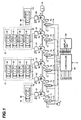
- Figure 1 illustrates a pump fault diagnostic apparatus for a hydraulic drive system provided on a large hydraulic excavator according to the first embodiment of the present invention together with the hydraulic drive system.
- the hydraulic drive system is provided with variable displacement hydraulic pumps 1 to 6 driven by an engine 10 and these hydraulic pumps 1 to 6 are provided with regulators 1a to 6a and the regulators 1a to 6a are driven by control pressures output from solenoid valves 11 to 16 to control delivery rates of the hydraulic pumps 1 to 6.
- the solenoid valves 11 to 16 are activated by currents of signal lines 111 to 116 output from a controller 50 to change the switching positions and generate the control pressures based on a delivery pressure of a pilot pump 7. That is, the delivery rates of the hydraulic pumps 1 to 6 are controlled according to the switching positions of the solenoid valves 11 to 16.
- the controller 50 performs predetermined calculation processing based on demanded flow rate signals X and delivery pressures of the hydraulic pumps 1 to 6 to generate the currents of the signal lines 111 to 116 (described later).
- a hydraulic fluid delivered from the hydraulic pump 1 is supplied to a valve block 30, hydraulic fluids delivered from the hydraulic pumps 2 and 3 are supplied to a valve block 31, hydraulic fluids delivered from the hydraulic pumps 4 and 5 are supplied to a valve block 32 and a hydraulic fluid delivered from the hydraulic pump 6 is supplied to a valve block 33.
- a directional control valve 40 is placed in the valve block 30, directional control valves 41 to 44 are placed in the valve block 31, directional control valves 45 to 48 are placed in the valve block 32 and a directional control valve 49 is placed in the valve block 33.
- the directional control valves 40 to 49 are connected to their respective hydraulic actuators (not shown) and control the flow rates and directions of the hydraulic fluids supplied to these hydraulic actuators and drive the hydraulic actuators.
- the pump fault diagnostic apparatus of this embodiment is installed on such a hydraulic drive system and comprise measuring units 21 to 26 set in delivery lines 1b to 6b of the hydraulic pumps 1 to 6, the above-described controller 50 and a display unit 60. Measured values of the measuring units 21 to 26 are sent to the controller 50 via their respective signal lines 121 to 126 and the controller 50 makes a fault diagnosis of the hydraulic pumps 1 to 6 using the measured values and sends the diagnosis results to the display unit 60 via signal lines 161 to 166 and the display unit 40 displays the fault situations of the pumps to inform the operator or maintenance personnel of the machine of the fault situations.
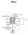
- the measuring units 21 to 26 have the same structure, and therefore the detailed structures of the measuring units 21 to 26 will be explained taking the measuring unit 21 as an example by using Figure 2.
- the measuring unit 21 is provided with a check valve 210 including a check valve body 21a, a poppet 21b placed in the check valve body 21a and a spring 21c supporting the poppet 21b, a detection rod 21d arranged to contact the poppet 21b of the check valve 210 and a displacement sensor 221b for measuring the displacement of the poppet 21b by measuring the displacement of the detection rod 21d.
- the measuring unit 21 is also provided with a pressure sensor 221a connected to the delivery line 1b of the hydraulic pump 1.
- the pump delivery pressure is detected by the pressure sensor 221a and the detected signal is output by the signal line 121a. Furthermore, the displacement of the poppet 21b changes according to the flow rate of the hydraulic fluid supplied to the valve block 30 and the displacement of this poppet 21b is detected by the displacement sensor 221b and the detected signal is output by the signal line 121b.
- the signal line 121a and the signal line 121b constitute the above-described signal line 121.
- the signals of delivery pressures of the hydraulic pumps 1 to 6 measured by the measuring units 21 to 26 and the signals of poppet displacements that change according to the delivery rates of the hydraulic pumps 1 to 6 are led to the controller 50 via the signal lines 121 to 126.
- check valves are placed in the delivery lines 2b to 5b of the hydraulic pumps 2 to 5 to prevent backflows of hydraulic fluids when the hydraulic fluids delivered by the hydraulic pumps 2 and 3 or hydraulic pumps 4 and 5 are joined.
- the measuring units 22 to 25 for the hydraulic pumps 2 to 5 can use those check valves as the above-described check valve 210.
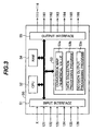
- Figure 3 illustrates an outline of an internal structure of the controller 50.
- the controller 50 includes an input interface 51 provided with an A/D converter to receive demanded flow rate signals X and signals from the measuring units 21 to 26, a central processing unit (CPU) 52 that performs predetermined calculations and control, a read-only memory (ROM) 53 that stores software such as a control program used in the CPU 52, a random access memory (RAM) 54 that temporarily stores calculation results, etc. and an output interface 55 that outputs drive currents and signals of fault situation of the respective hydraulic pumps to the solenoid valves 11 to 16 and display unit 60.
- CPU central processing unit
- ROM read-only memory
- RAM random access memory
- the controller 50 performs predetermined calculations based on the demanded flow rate signals X and delivery pressures of the hydraulic pumps 1 to 6 and generates currents to control the delivery rates of the hydraulic pumps 1 to 6.
- a method of controlling the hydraulic pumps 1 to 6 based on the demanded flow rate signals X an appropriate one such as positive control, negative control, load sensing control, etc. can be used depending on the hydraulic system mounted on the hydraulic excavator.
- the delivery pressures of the hydraulic pumps 1 to 6 is used for horsepower limiting control of the hydraulic pumps 1 to 6.
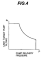
- Figure 4 shows an input torque limiting control conversion map to carry out horsepower limiting control of the hydraulic pumps 1 to 6.
- This conversion map is stored in the ROM 53.
- the input torque limiting control means limiting the maximum values of the input torques of the hydraulic pumps 1 to 6 thereby controlling the input torque of the hydraulic pumps 1 to 6 not so as to exceed the output torque of the engine 10.
- the conversion map sets the relationship between the pump delivery pressure P and a limiting target pump tilting qt so that when the pump delivery pressure P increases, the product (input torque) of P and qt is kept constant.
- consumed horsepower of the hydraulic pumps 1 to 6 is resultantly controlled not so as to exceed the output horsepower of the engine 10 thereby allowing horsepower limiting control of the hydraulic pumps 1 to 6.
- the delivery pressures P of the hydraulic pumps 1 to 6 can be obtained by output voltages V1 of the pressure sensors 221a led from the measuring units 21 to 26 via the signal lines 121 to 126 (described later).
- the ROM 53 of the controller 50 has an area 53a that stores conversion maps and required numerical values, etc., an area 53b that stores a data collection processing program and an area 53c that stores a decision output processing program.
- Figure 5 shows a conversion map for conversion from an output voltage V1 of the pressure sensor 221a led from the measuring units 21 to 26 via the signal lines 121 to 126 to a pressure value (pump delivery pressure) P.
- the relationship between the output voltage V1 and pressure value P is set such that the pressure value P increases as the output voltage V1 increases.
- Figure 6 shows a conversion map for conversion from an output voltage V2 of the displacement sensor 221b led from the measuring units 21 to 26 via the signal lines 121 to 126 to a poppet displacement x.
- the relationship between the output voltage V2 and poppet displacement x is set such that the poppet displacement x increases as the output voltage V2 increases.
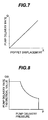
- Figure 7 shows a conversion map for conversion from the poppet displacement x converted by the conversion map shown in Figure 6 to a flow rate value (pump delivery rate) Q.
- the relationship between the poppet displacement x and flow rate value Q is set such that the flow rate value Q increases as the poppet displacement x increases.
- Figure 8 shown a conversion map for conversion from the pump delivery pressure P converted by the conversion map shown in Figure 5 to a pump delivery rate theoretical value.
- Qth used for pump fault decision processing.
- This conversion map corresponds to a horsepower limiting control characteristic when the input torque limiting control shown in Figure 4 is performed at a predetermined engine speed, for example, a maximum rated engine speed and the relationship between the pump delivery pressure P and pump delivery rate theoretical value Qth is set such that when the pump delivery pressure increases, the product (consumed horsepower) of the pump delivery pressure P and pump delivery rate theoretical value Qth is kept constant match with the relationship shown in Figure 4.
- the data collection processing of measured values from the measuring units 21 to 26 and the decision output processing are the same in content for each unit and the data collection processing of measured values from the measuring unit 21 and the decision output processing will be explained in detail by way of an example.
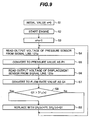
- Figure 9 shows a flow chart of the data collection processing program.
- the initial value of a processing count n at the time of mounting of the controller 50 is set to 0 (S1).
- the data collection processing program performs one processing of data collection from start to stop of the engine.
- the data collection processing program is started when the engine starts (S2), and adds 1 to the past data collection processing count (number of times of engine start) n to set a new nth processing (S3).
- the output value of the pressure sensor 221a is read from the signal line 121a at first (S4) and then converted to a pressure value P1 by the conversion map shown in Figure 5 (S5).
- the output value of the displacement sensor 221b is read by the signal line 121b (S6) and then converted to a flow rate value Q1 by the conversion map shown in Figure 6 and Figure 7 (S7).
- pressure value P1 and flow rate value Q1 are the values detected when the hydraulic excavator is actually operated, the hydraulic excavator being the working machine on which the hydraulic drive system shown in Figure 1 is mounted. Then, the flow rate value Q1 is compared with D1 2 (n) which is the maximum value of the flow rate value Q1 stored in the past (S8), and if the flow rate value Q1 is greater than D1 2 (n), the read pressure value P1 is replaced with D1 1 (n) which is the pressure value P1 stored in the past and the flow rate value Q1 is replaced with D1 2 (n) (S9). This processing in S4 to S9 is repeated until the engine stops.
- FIG 10 shows a flow chart of a decision output processing program.
- the values D1 1 (n) and D1 2 (n) at the data collection processing count n are read to start the processing at first (T1).
- a target pump delivery rate theoretical value Q1a at the pressure value D1 1 (n) is calculated according to the pump delivery pressure P - pump delivery rate theoretical value Qth conversion map shown in Figure 8 (T2).
- the percentage representing the deviation of the actual pump delivery rate D1 2 (n) from this calculated target pump delivery rate theoretical value Q1a is calculated from the following expression to calculate a value of E1a (T3).
- E1a (D1 2 (n)/Q1a) ⁇ 100 - 100 (%)
- the calculated E1a value is greater than -10% or not (whether the actual pump delivery rate D1 2 (n) is different from the target pump delivery rate theoretical value Q1a by -10% or more) (T4). If the E1a value is greater than -10%, a value of D1 7 (n) is set to 0 (T5). If the E1a value is smaller than -10%. the D1 7 (n) value is set to 1 (T6). In this way, the decision result at the data collection processing count n is stored as the D1 7 (n) value being 0 or 1.
- a fault decision on the hydraulic pump 1 is made (T7).
- the 10 decision results from the past data collection processing count (n-9) to n as shown in Figure 11 are read, and it is decided whether all the values D1 7 (n-9) to D1 7 (n) decided in step T4 are 1 or not and if all the values are 1 (T7), the hydraulic pump 1 is decided to be faulty and a signal is output to the display unit 60 through the signal line 161 (T8).
- FIG 12 shows an example of the display unit 60.
- the display unit 60 includes six lamps 60a to 60f that correspond to the hydraulic pumps 1 to 6, respectively, and if it is decided that any of the hydraulic pumps 1 to 6 is faulty, the lamp corresponding to the faulty hydraulic pump turns ON.
- the lamp 60a corresponding to the hydraulic pump 1 is turned on by a signal output to the display unit 60 through the signal line 161.
- the display unit 60 may also be provided with a monitor unit to display the data in Figure 11 by the request of the operator.
- FIG. 13 and Figure 14 show fault examples of the hydraulic pump 1 detected by this embodiment.
- the maximum delivery rate of the hydraulic pump 1 is limited by horsepower limiting control of the above-described controller 50 and the pump delivery pressure - pump delivery rate characteristic (hereinafter referred to as "PQ characteristic") at this time is expressed by dotted line in Figure 13 and Figure 14. This corresponds to the pump delivery pressure P - pump delivery rate theoretical value Qth conversion map shown in Figure 8.
- PQ characteristic the pump delivery pressure - pump delivery rate characteristic
- the E1a value is decided to be smaller than -10% in step T4 and the D1 7 (n) value is set to 1 in step T6. Then, when the same decision result is obtained through 10 data collection processings consecutively, it is decided that the hydraulic pump 1 is faulty and the corresponding lamp of the display unit 60 is turned on.
- the display unit 60 is provided with a monitor unit to be able to display the data in Figure 11, it is possible to grasp the fault situation of the hydraulic pumps from the data and take action quickly.
- FIG. 1 A second embodiment of the present invention will be explained by using Figure 1 to Figure 8 and Figure 15 to Figure 18.
- the structures of the hydraulic drive system and the controller to which the pump fault diagnostic apparatus relates is the same as those of the first embodiment, but the information used for detecting the state of the hydraulic pump during an actual operation differs from the first embodiment.
- a data collection processing program for collecting measured values from the measuring units 21 to 26 and a decision output processing program are stored in the areas 53b and 53c of the controller ROM 53 shown in Figure 3 as in the case of the first embodiment.
- FIG 15 shows a flow chart of a data collection processing program of the pump fault diagnostic apparatus according to this embodiment. The same steps as those shown in Figure 9 are designated with the same reference numerals.
- a pressure value P1 and a flow rate value Q1 are detected during an actual operation of the hydraulic excavator provided with the hydraulic drive system (S1 to S7). Then, from the pressure value P1 and flow rate value Q1 detected during the actual operation, the pressure value P1 is compared with D1 5 (n) which is the maximum value of the pressure value P1 stored in the past (S18), and if the pressure value P1 is greater than D1 5 (n), the read pressure value P1 is replaced with D1 5 (n) and the flow rate value Q1 is replaced with D1 6 (n) which is the flow rate value Q1 stored in the past (S19). The processing in these S4 to S19 is repeated until the engine stops.
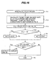
- Figure 16 shows a flow chart of a decision output processing program. The same steps as those shown in Figure 10 are designated with the same reference numerals.
- the calculated E1c value is greater than -10% or not (whether the actual pump delivery rate D1 6 (n) is different from the target pump delivery rate theoretical value by -10% or more) (T14). If the E1c value is greater than -10%, a value of D1 7 (n) is set to 0 (T5). If the E1c value is smaller than -10%, the D1 7 (n) value is set to 1 (T6). In this way, the decision result at the data collection processing count n is stored as the D1 7 (n) value being 0 or 1.
- a fault decision on the hydraulic pump 1 is made (T7).
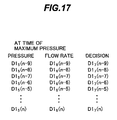
- the 10 decision results from the past data collection processing count (n-9) to n as shown in Figure 17 are read, and it is decided whether all the values D1 7 (n-9) to D1 7 (n) decided in step T14 are 1 or not and if all the values are 1 (T7), the hydraulic pump 1 is decided to be faulty and a signal is output to the display unit 60 through the signal line 161 (T8).
- the display unit 60 turns on the corresponding lamp as in the case of the first embodiment.
- the display unit 60 may also be provided with a monitor unit to display the data in Figure 11 by the request of the operator in this case, too.
- step T14 it is decided in step T14 that the E1c value is smaller than -10% and the value D1 7 (n) is set to 1 in step T6. Then, when the same decision result is obtained through 10 data collection processings consecutively, it is decided that the hydraulic pump 1 is faulty and the corresponding lamp of the display unit 60 is turned on.
- a third embodiment of the present invention will be explained by using Figure 1 to Figure 8 and Figure 19 to Figure 21.
- the structure of the hydraulic drive system and the controller to which the pump fault diagnostic apparatus relates is the same as those of the first embodiment, but the information used for detecting the state of the hydraulic pump during an actual operation differs from the first and the second embodiments.
- a data collection processing program for collecting measured values from the measuring units 21 to 26 and a decision output processing program are stored in the areas 53b and 53c of the controller ROM 53 shown in Figure 3 as in the case of the first embodiment. These processings are the same in content for each unit and the data collection processing of measured values from the measuring unit 21 and the decision output processing will be explained in detail by way of an example.
- FIG 19 shows a flow chart of a data collection processing program of the pump fault diagnostic apparatus according to this embodiment. The same steps as those shown in Figure 9 and Figure 15 are designated with the same reference numerals.
- a pressure value P1 and a flow rate value Q1 are detected during an actual operation of the hydraulic excavator provided with the hydraulic drive system (S1 to S7). Then, the flow rate value Q1 detected during the actual operation is compared with D1 2 (n) which is the maximum value of the flow rate value Q1 stored in the past (S8), and if the flow rate value Q1 is greater than D1 2 (n), the read pressure value P1 is replaced with D1 1 (n) which is the pressure value P1 stored in the past and the flow rate value Q1 is replaced with D1 2 (n) (S9).
- the pressure value P1 is compared with D1 5 (n) which is the maximum value of the pressure value P1 stored in the past (S18), and if the pressure value P1 is greater than D1 5 (n), the read pressure value P1 is replaced with D1 5 (n) and the flow rate value Q1 is replaced with D1 6 (n) which is the flow rate value Q1 stored in the past (S19). The processing in these S4 to S19 is repeated until the engine stops.
- Figure 20 shows a flow chart of a decision output processing program. The same steps as those shown in Figure 10 and Figure 16 are designated with the same reference numerals.
- the calculated E1c value is greater than -10% or not (whether the actual pump delivery rate D1 6 (n) is different from the target pump delivery rate theoretical value by -10% or more) (T14). If the E1c value is greater than -10%, a value of D1 7 (n) is set to 0 (T5). If at least one of the E1a or E1c value is smaller than -10%, the D1 7 (n) value is set to 1 (T6). In this way, the decision result at the data collection processing count n is stored as the D1 7 (n) value being 0 or 1.
- a fault decision on the hydraulic pump 1 is made (T7).
- the 10 decision results from the past data collection processing count (n-9) to n as shown in Figure 21 are read, and it is decided whether all the values D1 7 (n-9) to D1 7 (n) decided in steps T4 and T14 are 1 or not (T7) and if all the values are 1, the hydraulic pump 1 is decided to be faulty and a signal is output to the display unit 60 through the signal line 161 (T8).
- the display unit 60 turns on the corresponding lamp as in the case of the first embodiment.
- the display unit 60 may also be provided with a monitor unit to display the data in Figure 11 by the request of the operator in this case, too.
- step T4, T6, T7 and T8 it is possible by step T4, T6, T7 and T8 to detect the above-mentioned fault where the hydraulic pump 1 does not reach the maximum tilting position and the pump delivery rate remains insufficient as shown with solid line in Figure 13, the above-mentioned fault where the delivery rate of the hydraulic pump 1 does not reach a specified value of horsepower limiting control and remains insufficient throughout the entire range of the delivery pressure of the hydraulic pump 1, as shown with solid line in Figure 14.
- step T14, T6, T7 and T8 it is possible by step T14, T6, T7 and T8 to detect the above-mentioned fault where the delivery rate of the hydraulic pump 1 does not reach a specified value of horsepower limiting control and remains insufficient throughout the entire range of the delivery pressure of the hydraulic pump 1 as shown with solid line in Figure 14 and the above-mentioned fault where the delivery rate of the hydraulic pump 1 does not reach a specified value of horsepower limiting control and remains insufficient when the delivery pressure of the hydraulic pump 1 is high as shown with solid line in Figure 18.
- faults of the hydraulic pump such as a fault where there is a problem with the tilting mechanism of the hydraulic pump and the hydraulic pump fails to reach the maximum tilting position, or a fault where there is a problem with horsepower limiting control of the hydraulic pump and the delivery rate of the hydraulic pump as a whole does not reach a specified value of horsepower limiting control, or a fault where the delivery rate of the hydraulic pump does not reach a specified value of horsepower limiting control when the delivery pressure of the hydraulic pump increases.
- a fourth embodiment of the present invention will be explained by using Figure 1 to Figure 8 and Figure 22 to Figure 24.
- the structures of the hydraulic drive system and the controller to which the pump fault diagnostic apparatus relates is the same as those of the first embodiment, but information of the pump delivery rate at an intermediate delivery pressure is added to the third embodiment as information used for detecting the state of the hydraulic pump during an actual operation.
- a data collection processing program for collecting measured values from the measuring units 21 to 26 and a decision output processing program are stored in the areas 53b and 53c of the controller ROM 53 shown in Figure 3 as in the case of the first embodiment. These processings are the same in content for each unit and the data collection processing of measured values from the measuring unit 21 and the decision output processing will be explained in detail by way of an example.
- FIG 22 shows a flow chart of a data collection processing program of the pump fault diagnostic apparatus according to this embodiment. The same steps as those shown in Figure 9, Figure 15 and Figure 19 are designated with the same reference numerals.
- a pressure value P1 and a flow rate value Q1 are detected during an actual operation of the hydraulic excavator provided with the hydraulic drive system (S1 to S7). Then, the data of a pressure value D1 1 (n) and a flow rate value D1 2 (n) when the hydraulic pump 1 delivers a maximum flow rate are collected (S8, S9). Then, it is decided whether the pressure value P1 is an intermediate pressure of the hydraulic pump 1 or not (S28). For example, when the maximum delivery pressure of the hydraulic pump 1 is 35 MPa, its intermediate pressure is 17.5 MPa, and therefore it is decided whether the pressure value P1 falls within the range of 17 MPa to 18 MPa or not.
- the flow rate value Q1 is compared with D1 4 (n) which is the maximum value of the flow rate value Q1 at the intermediate pressure stored in the past (S38), and if the flow rate value Q1 is greater than D1 4 (n), the read pressure value P1 is replaced with D1 3 (n), and the flow rate value Q1 is replaced with D1 4 (n) (S29).
- the pressure value P1 is compared with D1 5 (n) which is the maximum value of the pressure value P1 stored in the past (S18), and if the pressure value P1 is greater than D1 5 (n), the read pressure value P1 is replaced with D1 5 (n) and the flow rate value Q1 is replaced with D1 6 (n) which is the flow rate value Q1 stored in the past (S19). The processing in these S4 to S19 is repeated until the engine stops.
- Figure 23 shows a flow chart of a decision output processing program. The same steps as those shown in Figure 10, Figure 16 and Figure 20 are designated with the same reference numerals.
- a target pump delivery rate theoretical value Q1b at the pressure value D1 3 (n) is calculated according to the pump delivery pressure - pump delivery rate theoretical value Qth conversion map shown in Figure 8 (T22). Then, the percentage representing the deviation of the actual pump delivery rate D1 4 (n) from this calculated target pump delivery rate theoretical value Q1b is calculated from the following expression to calculate E1b (T23).
- E1b (D1 4 (n)/Q1b) ⁇ 100 - 100 (%)
- the process moves to steps T13 and T14 where it is decided whether the E1c value is greater than -10% or not (whether the actual pump delivery rate D1 6 (n) is different from the target pump delivery rate theoretical value Q1c by -10% or more) and if the E1c value is greater than -10%, the D1 7 (n) value is set to 0 (T5).
- the D1 7 (n) value is set to 1 (T6). In this way, the decision result at the data collection processing count n is stored as the D1 7 (n) value being 0 or 1.
- a fault decision on the hydraulic pump 1 is made (T7).
- the 10 decision results from the past data collection processing count (n-9) to n as shown in Figure 24 are read, and it is decided whether all the values D1 7 (n-9) to D1 7 (n) decided in steps T4, T14 and T24 are 1 or not (T7) and if all the values are 1, the hydraulic pump 1 is decided to be faulty and a signal is output to the display unit 60 through the signal line 161 (T8).
- the display unit 60 turns on the corresponding lamp as in the case of the first embodiment.
- the display unit 60 may also be provided with a monitor unit to display the data in Figure 11 by the request of the operator in this case, too.
- step T24 it is possible also by step T24 to detect such a fault where the delivery rate of the hydraulic pump 1 does not reach a specified value of horsepower limiting control and remains insufficient as shown with solid line in Figure 14 and Figure 18.
- FIG. 25 A fifth embodiment of the present invention will be explained by using Figure 4 to Figure 8 and Figure 25 to Figure 28.
- This embodiment applies the present invention to a hydraulic drive system whose horsepower limiting control characteristic is made changeable by a mode changeover switch while allowing display of the level of a fault of the hydraulic pump.
- Figure 25 the same components as those in Figure 1 are designated with the same reference numerals.
- the hydraulic drive system to which this embodiment relates comprises a mode changeover switch 70 additionally to the first embodiment shown in Figure 1 and a mode information signal of this mode changeover switch 70 is led to a controller 50A.
- the mode changeover switch 70 can be switched between three positions; normal mode position, fine operating mode position and heavy excavating mode position.
- Figure 26 illustrates a conversion map of input torque limiting control used in this embodiment for performing horsepower limiting control of the hydraulic pumps 1 to 6.
- the ROM 53 (see Figure 3) of the controller 50A stores the conversion map shown in Figure 26 instead of the conversion map shown in Figure 4.
- This conversion map consists of a normal mode conversion map A, a fine operating conversion map B and a heavy excavating conversion map C and the controller 50A selects the normal mode conversion map A when the mode information signal of the mode changeover switch 70 indicates a normal mode position, selects the fine operating conversion map B when the mode information signal indicates a fine operating mode position, and selects the heavy excavating conversion map C when the mode information signal indicates a heavy excavating position.
- the controller 50A performs horsepower limiting control of the hydraulic pumps 1 to 6 using this selected conversion map as explained in the first embodiment.
- Figure 27 shows a pump delivery pressure P - pump delivery rate theoretical value Qth conversion map used in this embodiment.
- the area 53a (see Figure 3) of the ROM 53 of the controller 50A stores the conversion map shown in Figure 27 instead of the conversion map shown in Figure 8.
- the map shown in Figure 27 corresponds to the conversion map of the input torque limiting control shown in Figure 26, and consists of a normal mode conversion map A1, a fine operating mode conversion map B1 and a heavy excavating mode conversion map C1 wherein the corresponding mode according to a mode information signal of the operating mode changeover switch 70 is selected and made effective.
- the data collection processing program stored in the area 53b (see Figure 3) of the ROM 53 of the controller 50A is the same as that of the third embodiment shown in Figure 19.
- the area 53c (see Figure 3) of the ROM 53 of the controller 50A stores a decision output processing program according to this embodiment. This processing is the same in content for each unit and the data collection processing of measured values from the measuring unit 21 and the decision output processing will be explained in detail by way of an example.
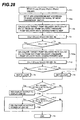
- Figure 28 shows a flow chart of a decision output processing program.
- the same steps as those in Figure 10 and Figure 20 are designated with the same reference numerals.
- the corresponding mode is selected and set from the conversion map shown in Figure 27 according to the mode information signal of the mode changeover switch 70 (T2a). That is, the normal mode conversion map A1 is selected when the mode changeover switch 70 is at the normal mode position, the fine operating mode conversion map B1 is selected when the mode changeover switch 70 is at the fine operating mode position and the heavy excavating mode conversion map C1 is selected when the mode changeover switch 70 is at the heavy excavating mode position, and the respective maps are set as the conversion maps to be used for the decision output processing program.
- a target pump delivery rate theoretical value Q1a at the pressure value D1 1 (n) is calculated according to the set conversion map (T2b). Then, in step T3, an E1a value is calculated and it is decided in step T4 whether the calculated E1a value is greater than -10% or not (whether the actual pump delivery rate D1 2 (n) is different from the target pump delivery rate theoretical value Q1a by -10% or more) and then if the E1a value is greater than -10%, the target pump delivery rate value Q1c at the pressure value D1 5 (n) is calculated using the conversion map set in step T2a (T12a).
- step T13 an E1c value is calculated and it is decided in step T14 whether the calculated E1c value is greater than -10% or not (whether the actual pump delivery rate D1 5 (n) is different from the target pump delivery rate theoretical value Q1a by -10% or more) and then if the E1c value is greater than -10%, the D1 7 (n) value is set to 0 (T5). Furthermore, if at least one of the E1a value or E1c value is smaller than -10%, the D1 7 (n) value is set to 1 (T6).
- the 10 decision results from the past data collection processing count (n-9) to n as shown in Figure 21 are read, and it is decided whether all the values D1 7 (n-9) to D1 7 (n) decided in steps T4 and T14 are 1 or not (T7)and if all the values are 1, the hydraulic pump 1 is decided to be completely faulty and a red display signal is output to the display unit 60 through the signal line 161 (T18).
- the display unit 60 turns on the corresponding lamp in red.
- the horsepower limiting control characteristic can be changed by the mode changeover switch, it is possible to detect a fault by automatically determining which of the hydraulic pumps 1 to 6 has a problem during an actual operation of the working machine and further to detect a fault when there is any problem with horsepower limiting control of the hydraulic pumps 1 to 6.
- lamps of the display unit 60 are turned on in different colors depending on a case where a hydraulic pump is completely faulty and a case where the hydraulic pump is possibly faulty, it is possible to warn the operator of a machine about details of the current fault conditions of the hydraulic pumps.
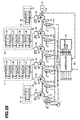
- FIG. 29 A sixth embodiment of the present invention will be explained by using Figure 4 to Figure 8 and Figure 29 to Figure 31. This embodiment applies to a case where the horsepower limiting control characteristic is changed depending on the engine speed.
- Figure 29 the same components as those in Figure 1 are designated with the same reference numerals.
- the hydraulic drive system to which this embodiment relates comprises an engine speed sensor 100 additionally to the first embodiment shown in Figure 1 and a signal of this engine speed sensor 100 is led to a controller 50B.
- Figure 30 shows a pump delivery pressure P - pump delivery rate theoretical value Qth conversion map used in this embodiment.
- the area 53a (see Figure 3) of the ROM 53 of the controller 50B stores the conversion map shown in Figure 30 instead of the conversion map shown in Figure 8.
- This map is made in such a way that the limiting value (maximum value) of horsepower consumption of the hydraulic pump gradually decreases in order of A2, B2 and C2 as the engine speed N decreases, wherein the corresponding one according to a detection signal of the engine speed sensor 100 is selected and made effective.
- the data collection processing program stored in the area 53b (see Figure 3) of the ROM 53 of the controller 50B is the same as that of the third embodiment shown in Figure 19.
- the area 53c (see Figure 3) of the ROM 53 of the controller 50B stores a decision output processing program according to this embodiment. This processing is the same in content for each unit and the data collection processing of measured values from the measuring unit 21 and the decision output processing will be explained in detail by way of an example.
- Figure 31 shows a flow chart of a decision output processing program.
- the same steps as those in Figure 10, Figure 20 and Figure 28 are designated with the same reference numerals.
- step T2c this decision output processing program is different in the processing in step T2c from that in step T2a shown in Figure 28 and other portions are the same as those in Figure 28.
- step T2c the corresponding engine speed is selected and set from the conversion map in Figure 30 according to the detection signal of the engine speed sensor 100.
- the conversion map A2 corresponding to a maximum rated engine speed is selected when the engine speed indicated by the detection signal of the engine speed sensor 100 is a value in the vicinity of the maximum engine speed
- the conversion map B2 corresponding to an intermediate engine speed is selected when the engine speed is a value in the vicinity of the intermediate engine speed
- the conversion map C2 corresponding to a low engine speed is selected when the engine speed is a value in the vicinity of the low engine speed
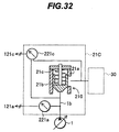
- FIG. 32 shows another example of a structure of the measuring unit.
- the equivalent components as those in Figure 2 are designated with the same reference numerals.
- the measuring unit 21 shown in Figure 2 includes the displacement sensor 21b for measuring a poppet displacement of the check valve 210 and measures a delivery rate of the hydraulic pump 1 according to the output result of this displacement sensor 21b, but in this embodiment, the measuring unit is configured to include a differential pressure sensor as shown in Figure 32.
- a differential pressure sensor 221c is arranged for detecting a differential pressure between the pressure on the upstream side of the poppet 21b of the check valve 210 and that on the downstream side thereof, and the differential pressure across the poppet 21b that changes depending on the flow rate of the hydraulic fluid supplied from the delivery line 1b of the hydraulic pump 1 to the valve block 30 is detected by the differential pressure sensor 221c and the detected signal is output through the signal line 121c.
- the signal line 121a and signal line 121c constitute the signal line 121 (see Figure 1).
- the controller 50 calculates the delivery rate of the hydraulic pump 1 from the above expression using the detection signal of the differential pressure sensor 221c input from the signal line 121.
- the horsepower limiting control of the hydraulic pump is performed electronically using a conversion map stored in the controller, but a hydraulic regulator having a horsepower control port to introduce a delivery pressure of the hydraulic pump and directly controls the tilting of the hydraulic pump using the delivery pressure to perform horsepower limiting control may be used, and in this case the present invention is likewise applicable and similar advantages can be obtained.
- the storage of the nth data in the data collection processing program shown in Figure 9, etc. is started when the engine starts, but it is also possible to provide a dedicated start button and start the storage of the nth data using the button or provide a timer to start the nth data storage every time the date is changed or every defined time of hours.
Landscapes
- Engineering & Computer Science (AREA)
- Mechanical Engineering (AREA)
- General Engineering & Computer Science (AREA)
- Computer Hardware Design (AREA)
- Control Of Positive-Displacement Pumps (AREA)
- Fluid-Pressure Circuits (AREA)
Abstract
Description
Claims (13)
- A pump fault diagnostic apparatus for a hydraulic drive system having at least one variable displacement hydraulic pump (1 to 6) and horsepower limiting control means (1a to 6a, 11 to 16, 50) for controlling said hydraulic pumps such that a maximum pump delivery rate is reduced as a delivery pressure of said hydraulic pump increases, wherein said apparatus comprises:first sensor means (21 to 26, 221b) for detecting the delivery rate of said hydraulic pump;second sensor means (21 to 26, 221a) for detecting the delivery pressure of said hydraulic pump;data collecting means (50, 53b) for measuring the pump delivery rate and pump delivery pressure during operation of said hydraulic drive system based on the detected values of said plurality of first sensor means and second sensor means and collecting the measured values as fault diagnostic data; andfault deciding means (50, 53c) for calculating a target pump delivery rate of horsepower limiting control corresponding to the pump delivery pressure collected by said data collecting means, comparing the pump delivery rate collected by said data collecting means and said calculated target pump delivery rate and making a fault decision of said hydraulic pump.
- A pump fault diagnostic apparatus for a hydraulic drive system having a plurality of variable displacement hydraulic pumps (1 to 6) and horsepower limiting control means (1a to 6a, 11 to 16, 50) for controlling the plurality of hydraulic pumps such that respective maximum pump delivery rates are reduced as respective delivery pressures of said hydraulic pumps increase, wherein said apparatus comprises:first sensor means (21 to 26, 221b) for detecting the respective delivery rates of said plurality of hydraulic pumps;second sensor means (21 to 26, 221a) for detecting the respective delivery pressures of said plurality of hydraulic pumps;data collecting means (50, 53b) for measuring, for each of said hydraulic pump, the pump delivery rate and pump delivery pressure while during operation of said hydraulic drive apparatus based on the detected values of said plurality of first sensor means and second sensor means and collecting the measured values as fault diagnostic data; andfault deciding means (50, 53c) for calculating, for each of said hydraulic pump, a target pump delivery rate of horsepower limiting control corresponding to the pump delivery pressure collected by said data collecting means, comparing the pump delivery rate collected by said data collecting means and said calculated target pump delivery rate and making a fault decision of each of said hydraulic pumps.
- The pump fault diagnostic apparatus for a hydraulic drive system according to claim 2, wherein said data collecting means (50, 53b) measures, for each of said hydraulic pump, the pump delivery pressure and pump delivery rate when the pump delivery rate reaches a maximum during operation of said hydraulic drive system based on the detected values of said plurality of first sensor means and second sensor means and collects the measured values as fault diagnostic data.
- The pump fault diagnostic apparatus for a hydraulic drive system according to claim 2, wherein said data collecting means (50, 53b) measures, for each of said hydraulic pump, the pump delivery rate and pump delivery pressure when the pump delivery pressure reaches a maximum during operation of said hydraulic drive system based on the detected values of said plurality of first sensor means and second sensor means and collects the measured values as fault diagnostic data.
- The pump fault diagnostic apparatus for a hydraulic drive system according to claim 2, wherein said data collecting means (50, 53b) measures, for each of said hydraulic pumps, the pump delivery pressure and pump delivery rate when the pump delivery rate reaches a maximum and the pump delivery rate and pump delivery pressure when the pump delivery pressure reaches a maximum during operation of said hydraulic drive system based on the detected values of said plurality of first sensor means and second sensor means and collects the measured values as fault diagnostic data.
- The pump fault diagnostic apparatus for a hydraulic drive system according to claim 2, wherein said data collecting means (50, 53b) measures, for each of said hydraulic pump, the pump delivery pressure and pump delivery rate when the pump delivery rate reaches a maximum, the pump delivery rate and pump delivery pressure when the pump delivery pressure reaches a maximum and the pump delivery rate and pump delivery pressure when the pump delivery pressure reaches a predetermined intermediate pressure during operation of said hydraulic drive system based on the detected values of said plurality of first sensor means and second sensor means and collects the measured values as fault diagnostic data.
- The pump fault diagnostic apparatus for a hydraulic drive system according to any one of claims 2 to 6, wherein each of said plurality of first sensor means (21 to 26) includes a displacement sensor (221b) for measuring a poppet displacement of a check valve (210) provided in the delivery line (1b to 6b) of each hydraulic pump (1 to 6) and calculates the delivery rate of each hydraulic pump from the output result of said displacement sensor.
- The pump fault diagnostic apparatus for a hydraulic drive system according to any one of claims 2 to 6, wherein each of said plurality of first sensor means (21C) includes a differential pressure sensor (221c) for measuring a differential pressure across a check valve (210) provided in the delivery line of each hydraulic pump (1) and calculates the delivery rate of each hydraulic pump from the output result of said differential pressure sensor.
- The pump fault diagnostic apparatus for a hydraulic drive system according to any one of claims 2 to 6, wherein said system further comprises:fault displaying means (60) having a plurality of alarm lamps (60a to 60f) provided correspondingly to said plurality of hydraulic pumps (1 to 6) for turning on the corresponding alarm lamp when said fault deciding means (50, 53c) decides that any of the plurality of hydraulic pumps is faulty.
- The pump fault diagnostic apparatus for a hydraulic drive system according to claim 9, wherein said fault displaying means (60) changes lamp colors between a case where there is a possibility of fault in the hydraulic pump and a case where the possibility is a higher.
- The pump fault diagnostic apparatus for a hydraulic drive system according to any one of claims 2 to 6, wherein said data collecting means (50, 53b) collects said fault diagnostic data for every operation of said hydraulic drive system and said fault deciding means (50, 53b) decides whether said hydraulic pumps (1 to 6) are faulty or not based on the decision result of said fault diagnostic data for a predetermined number of times of the operations.
- The pump fault diagnostic apparatus for a hydraulic drive system according to any one of claims 2 to 6, wherein said fault deciding means (50B, 53C) includes a plurality of pump delivery pressure/pump delivery rate conversion maps, and selects one of them and calculates said target pump delivery rate using the selected conversion map.
- A display unit (60) of a pump fault diagnostic apparatus for a hydraulic drive system having a plurality of variable displacement hydraulic pumps (1 to 6) and horsepower limiting control means (1a to 6a, 11 to 16, 50) for controlling a plurality of hydraulic pumps such that a maximum pump delivery rate is reduced as delivery pressures of these hydraulic pumps increase, wherein:said display unit comprises a plurality of alarm lamps (60a to 60f) provided correspondingly to said plurality of hydraulic pumps (1 to 6), and turns on the corresponding alarm lamp when said pump fault diagnostic apparatus decides that there is a problem with said horsepower control means (1a to 6a, 11 to 16, 50) of any of the plurality of hydraulic pumps.
Applications Claiming Priority (3)
| Application Number | Priority Date | Filing Date | Title |
|---|---|---|---|
| JP2001039112 | 2001-02-15 | ||
| JP2001039112A JP2002242849A (en) | 2001-02-15 | 2001-02-15 | Pump failure diagnosis device for hydraulic drive device and display device thereof |
| PCT/JP2002/001211 WO2002064980A1 (en) | 2001-02-15 | 2002-02-14 | Pump trouble diagnosing device for hydraulic drive device and display device of the diagnosing device |
Publications (2)
| Publication Number | Publication Date |
|---|---|
| EP1361362A1 true EP1361362A1 (en) | 2003-11-12 |
| EP1361362A4 EP1361362A4 (en) | 2009-11-11 |
Family
ID=18901971
Family Applications (1)
| Application Number | Title | Priority Date | Filing Date |
|---|---|---|---|
| EP02701544A Withdrawn EP1361362A4 (en) | 2001-02-15 | 2002-02-14 | Pump trouble diagnosing device for hydraulic drive device and display device of the diagnosing device |
Country Status (6)
| Country | Link |
|---|---|
| US (1) | US6823289B2 (en) |
| EP (1) | EP1361362A4 (en) |
| JP (1) | JP2002242849A (en) |
| KR (1) | KR100481935B1 (en) |
| AU (1) | AU2002234874B2 (en) |
| WO (1) | WO2002064980A1 (en) |
Cited By (2)
| Publication number | Priority date | Publication date | Assignee | Title |
|---|---|---|---|---|
| RU2450253C1 (en) * | 2010-12-30 | 2012-05-10 | Государственное образовательное учреждение высшего профессионального образования "Тюменский государственный университет" | Method of diagnosing pump operating performances |
| EP3399190A4 (en) * | 2015-12-28 | 2019-08-14 | Hitachi Construction Machinery Co., Ltd. | WORKING MACHINE |
Families Citing this family (35)
| Publication number | Priority date | Publication date | Assignee | Title |
|---|---|---|---|---|
| US7883534B1 (en) | 2002-02-27 | 2011-02-08 | CAMS Medical Instruments, Inc. | Personal tuner |
| JP4289909B2 (en) * | 2003-03-07 | 2009-07-01 | 三輪精機株式会社 | Control system of hydraulic pump and lifting platform lifting device |
| KR101023741B1 (en) * | 2003-12-26 | 2011-03-25 | 두산인프라코어 주식회사 | Hydraulic pump drive motor controller of electric forklift |
| US20070055187A1 (en) * | 2005-02-28 | 2007-03-08 | Magnone David R | Adjustable massaging system |
| CA2527563C (en) * | 2005-12-23 | 2007-07-03 | Westport Research Inc. | Apparatus and method for pumping a cryogenic fluid from a storage vessel and diagnosing cryogenic pump performance |
| DE102006032648B4 (en) * | 2006-01-30 | 2014-06-26 | Abb Research Ltd. | Diagnostic system and method for condition monitoring and detection of malfunctions and failures to compressing and rotating machines |
| KR100863651B1 (en) | 2007-07-11 | 2008-10-15 | 현대중공업 주식회사 | Pump motor protector for water ballast |
| US8406945B2 (en) * | 2007-10-26 | 2013-03-26 | GM Global Technology Operations LLC | Method and apparatus to control logic valves for hydraulic flow control in an electro-mechanical transmission |
| KR101431847B1 (en) * | 2009-12-07 | 2014-08-25 | 현대중공업 주식회사 | Hydraulic system of crawler excavator |
| JP5346407B2 (en) | 2010-02-23 | 2013-11-20 | アルテミス インテリジェント パワー リミティド | Fluid actuator and method of operating fluid actuator |
| GB2477997B (en) | 2010-02-23 | 2015-01-14 | Artemis Intelligent Power Ltd | Fluid working machine and method for operating fluid working machine |
| DE102011115244A1 (en) * | 2011-09-28 | 2013-03-28 | Airbus Operations Gmbh | Method and system for monitoring the operating state of a pump |
| US9051945B2 (en) * | 2012-04-30 | 2015-06-09 | Caterpillar Inc. | System and method for identifying impending hydraulic pump failure |
| CN103075331A (en) * | 2012-12-29 | 2013-05-01 | 苏州市职业大学 | Sewage lifting control alarm |
| CN103362666B (en) * | 2013-07-29 | 2015-12-02 | 中联重科股份有限公司 | Power matching control device, method, system and construction machinery |
| KR101480860B1 (en) * | 2013-12-02 | 2015-01-09 | 주식회사 포스코 | Apparatus and method for determining flow rate of hydraulic pump |
| US10000911B2 (en) * | 2013-12-05 | 2018-06-19 | Doosan Infracore Co., Ltd. | Abnormality diagnostic system for work system of construction machinery and method using the same |
| KR101593972B1 (en) * | 2014-04-07 | 2016-02-15 | 대우조선해양 주식회사 | Method for controlling pump system |
| US10161822B1 (en) * | 2016-03-10 | 2018-12-25 | The United States Of America, As Represented By The Secretary Of The Navy | Differential pressure measurement system with solenoid coupled reference reservoir |
| CN107031596B (en) * | 2016-12-15 | 2019-04-12 | 上海拓为汽车技术有限公司 | A kind of electric booster braking displacement sensor diagnostic method |
| CN106678013B (en) * | 2017-03-13 | 2019-07-19 | 中石化四机石油机械有限公司 | High-power modular hydraulic drive reciprocating pump system |
| JP6273396B1 (en) * | 2017-07-28 | 2018-01-31 | 川崎重工業株式会社 | Failure diagnosis apparatus, pump unit including the same, and failure diagnosis method |
| WO2019022252A1 (en) * | 2017-07-28 | 2019-01-31 | 川崎重工業株式会社 | Fault diagnosis device, pump unit provided with same, and fault diagnosis method |
| JP6712578B2 (en) * | 2017-09-07 | 2020-06-24 | 日立建機株式会社 | Hydraulic drive |
| JP6903564B2 (en) * | 2017-12-22 | 2021-07-14 | ヤンマーパワーテクノロジー株式会社 | Work vehicle |
| JP6903567B2 (en) * | 2017-12-26 | 2021-07-14 | ヤンマーパワーテクノロジー株式会社 | Work vehicle |
| WO2021021665A1 (en) | 2019-07-26 | 2021-02-04 | Fluid Power AI Inc. | System and method for evaluating hydraulic system events and executing responses |
| JP7372198B2 (en) | 2020-05-08 | 2023-10-31 | 株式会社荏原製作所 | Display system, display device and display method |
| CN113030612A (en) * | 2021-02-26 | 2021-06-25 | 兖矿东华重工有限公司 | Safety detection method, system, device and medium for development machine |
| US11725647B2 (en) * | 2021-05-18 | 2023-08-15 | Hamilton Sundstrand Corporation | On-demand dual variable displacement positive displacement pumping system |
| CN114233617B (en) * | 2021-12-27 | 2023-09-22 | 三一汽车制造有限公司 | Pumping system, fault diagnosis method and device thereof, storage medium and engineering machinery |
| CN115095579B (en) * | 2022-07-15 | 2023-04-28 | 烟台杰瑞石油装备技术有限公司 | Fault early warning method of hydraulic system |
| CN115929600B (en) * | 2022-12-29 | 2026-07-28 | 浙江金仪盛世生物工程有限公司 | Method and device for controlling peristaltic pump switching and electronic equipment |
| US12700754B2 (en) | 2023-02-07 | 2026-08-04 | Fluid Power Ai, Llc | Systems and methods for monitoring equipment |
| JP7490903B1 (en) | 2024-01-26 | 2024-05-27 | 株式会社福島製作所 | Grab bucket diagnostic device |
Family Cites Families (10)
| Publication number | Priority date | Publication date | Assignee | Title |
|---|---|---|---|---|
| US3034446A (en) * | 1957-09-06 | 1962-05-15 | Robert W Brundage | Hydraulic pump or motor |
| JPS5498188A (en) * | 1978-01-19 | 1979-08-02 | Nec Corp | Photocuopler |
| JPS6114315A (en) * | 1984-06-30 | 1986-01-22 | Chiyoda Tech & Ind Co Ltd | Revetment block and constructing method thereof |
| JPH0732278Y2 (en) * | 1989-12-07 | 1995-07-26 | 本田技研工業株式会社 | Failure diagnosis device for fluid pressure source |
| US5628229A (en) * | 1994-03-31 | 1997-05-13 | Caterpillar Inc. | Method and apparatus for indicating pump efficiency |
| JPH1054370A (en) * | 1996-08-12 | 1998-02-24 | Hitachi Constr Mach Co Ltd | Diagnosis device for hydraulic pump of work machine |
| JP3857361B2 (en) * | 1996-08-12 | 2006-12-13 | 日立建機株式会社 | Hydraulic pump fault diagnosis device for work machines |
| US6055851A (en) | 1996-08-12 | 2000-05-02 | Hitachi Construction Machinery Co., Ltd. | Apparatus for diagnosing failure of hydraulic pump for work machine |
| US5919267A (en) * | 1997-04-09 | 1999-07-06 | Mcdonnell Douglas Corporation | Neural network fault diagnostics systems and related method |
| JP4348769B2 (en) * | 1999-03-31 | 2009-10-21 | Jfeスチール株式会社 | Control method of slant axis variable displacement piston pump |
-
2001
- 2001-02-15 JP JP2001039112A patent/JP2002242849A/en active Pending
-
2002
- 2002-02-14 US US10/257,013 patent/US6823289B2/en not_active Expired - Fee Related
- 2002-02-14 WO PCT/JP2002/001211 patent/WO2002064980A1/en not_active Ceased
- 2002-02-14 AU AU2002234874A patent/AU2002234874B2/en not_active Ceased
- 2002-02-14 KR KR10-2002-7013783A patent/KR100481935B1/en not_active Expired - Fee Related
- 2002-02-14 EP EP02701544A patent/EP1361362A4/en not_active Withdrawn
Cited By (2)
| Publication number | Priority date | Publication date | Assignee | Title |
|---|---|---|---|---|
| RU2450253C1 (en) * | 2010-12-30 | 2012-05-10 | Государственное образовательное учреждение высшего профессионального образования "Тюменский государственный университет" | Method of diagnosing pump operating performances |
| EP3399190A4 (en) * | 2015-12-28 | 2019-08-14 | Hitachi Construction Machinery Co., Ltd. | WORKING MACHINE |
Also Published As
| Publication number | Publication date |
|---|---|
| WO2002064980A1 (en) | 2002-08-22 |
| JP2002242849A (en) | 2002-08-28 |
| KR100481935B1 (en) | 2005-04-13 |
| EP1361362A4 (en) | 2009-11-11 |
| US6823289B2 (en) | 2004-11-23 |
| US20030144818A1 (en) | 2003-07-31 |
| AU2002234874B2 (en) | 2004-04-22 |
| KR20020093914A (en) | 2002-12-16 |
Similar Documents
| Publication | Publication Date | Title |
|---|---|---|
| AU2002234874B2 (en) | Pump trouble diagnosing device for hydraulic drive device and display device of the diagnosing device | |
| US6055851A (en) | Apparatus for diagnosing failure of hydraulic pump for work machine | |
| US6463949B2 (en) | Method and apparatus for determining a valve status | |
| JP6966830B2 (en) | Calibration system for variable displacement hydraulic pumps | |
| US20030146845A1 (en) | Failure diagnostic apparatus for hydraulic equipment | |
| US12077944B2 (en) | Construction machine | |
| EP3521522B1 (en) | Shovel | |
| US20120185141A1 (en) | Work vehicle and work vehicle control method | |
| CN112368452B (en) | Construction machine | |
| EP1020648A1 (en) | Method and device for controlling work machine | |
| KR20150035718A (en) | Management device and management method for shovel | |
| CN112682373A (en) | Hydraulic system, control method and engineering vehicle | |
| EP2937572A1 (en) | Integrated control apparatus and method for engine and hydraulic pump in construction machine | |
| JP2020143591A (en) | Hydraulic pump failure diagnosis device, construction machinery equipped with failure diagnosis device, failure diagnosis method and failure diagnosis program | |
| US9133837B2 (en) | Method of controlling a hydraulic system | |
| US6334085B1 (en) | Data processing unit for construction machine | |
| JP2001241384A (en) | Pump monitoring device for hydraulic working machine | |
| KR20140069904A (en) | Diagnostic apparatus for static characteristics of servo valve | |
| US12320372B2 (en) | Calibration system and calibration method in hydraulic system | |
| US20250020120A1 (en) | System for determining service life of hydraulic pump | |
| JP2020149413A (en) | Trouble diagnosing apparatus for hydraulic pump, construction machine comprising trouble diagnosing apparatus, trouble diagnosing method and trouble diagnosing program | |
| KR100240089B1 (en) | Diagnostic device of electrohydraulic construction machine | |
| CN117916432A (en) | Hydraulic control system and method for setting and calibrating target engine torque during release in the hydraulic control system | |
| KR100249772B1 (en) | Device for diagnosing a construction machine | |
| US20250320883A1 (en) | Method and System for Controlling a Total Movement of a Distribution Boom, and Method for Distributing Construction Material and/or Thick Matter by Means of a Construction Material and/or Thick Matter Pump Device Having a Distribution Boom |
Legal Events
| Date | Code | Title | Description |
|---|---|---|---|
| PUAI | Public reference made under article 153(3) epc to a published international application that has entered the european phase |
Free format text: ORIGINAL CODE: 0009012 |
|
| 17P | Request for examination filed |
Effective date: 20030117 |
|
| AK | Designated contracting states |
Kind code of ref document: A1 Designated state(s): AT BE CH CY DE DK ES FI FR GB GR IE IT LI LU MC NL PT SE TR |
|
| RIN1 | Information on inventor provided before grant (corrected) |
Inventor name: KASUYA, HIROTSUGU,SUNVILLAGE-HIGASHIDAI A201 Inventor name: KATOU, HIDEYO DI Inventor name: WATANABE, YUTAKA Inventor name: OCHIAI, MASAMI |
|
| A4 | Supplementary search report drawn up and despatched |
Effective date: 20090911 |
|
| 17Q | First examination report despatched |
Effective date: 20091123 |
|
| STAA | Information on the status of an ep patent application or granted ep patent |
Free format text: STATUS: THE APPLICATION IS DEEMED TO BE WITHDRAWN |
|
| 18D | Application deemed to be withdrawn |
Effective date: 20110301 |