EP1361349A2 - Mikrostromgenerator - Google Patents
Mikrostromgenerator Download PDFInfo
- Publication number
- EP1361349A2 EP1361349A2 EP03009128A EP03009128A EP1361349A2 EP 1361349 A2 EP1361349 A2 EP 1361349A2 EP 03009128 A EP03009128 A EP 03009128A EP 03009128 A EP03009128 A EP 03009128A EP 1361349 A2 EP1361349 A2 EP 1361349A2
- Authority
- EP
- European Patent Office
- Prior art keywords
- piston
- microgenerator
- fuel
- combustion
- microgenerator according
- Prior art date
- Legal status (The legal status is an assumption and is not a legal conclusion. Google has not performed a legal analysis and makes no representation as to the accuracy of the status listed.)
- Withdrawn
Links
Images

Classifications
-
- H—ELECTRICITY
- H02—GENERATION; CONVERSION OR DISTRIBUTION OF ELECTRIC POWER
- H02K—DYNAMO-ELECTRIC MACHINES
- H02K7/00—Arrangements for handling mechanical energy structurally associated with dynamo-electric machines, e.g. structural association with mechanical driving motors or auxiliary dynamo-electric machines
- H02K7/18—Structural association of electric generators with mechanical driving motors, e.g. with turbines
- H02K7/1869—Linear generators; sectional generators
- H02K7/1876—Linear generators; sectional generators with reciprocating, linearly oscillating or vibrating parts
- H02K7/1884—Linear generators; sectional generators with reciprocating, linearly oscillating or vibrating parts structurally associated with free piston engines
-
- F—MECHANICAL ENGINEERING; LIGHTING; HEATING; WEAPONS; BLASTING
- F02—COMBUSTION ENGINES; HOT-GAS OR COMBUSTION-PRODUCT ENGINE PLANTS
- F02B—INTERNAL-COMBUSTION PISTON ENGINES; COMBUSTION ENGINES IN GENERAL
- F02B1/00—Engines characterised by fuel-air mixture compression
- F02B1/12—Engines characterised by fuel-air mixture compression with compression ignition
-
- F—MECHANICAL ENGINEERING; LIGHTING; HEATING; WEAPONS; BLASTING
- F02—COMBUSTION ENGINES; HOT-GAS OR COMBUSTION-PRODUCT ENGINE PLANTS
- F02B—INTERNAL-COMBUSTION PISTON ENGINES; COMBUSTION ENGINES IN GENERAL
- F02B63/00—Adaptations of engines for driving pumps, hand-held tools or electric generators; Portable combinations of engines with engine-driven devices
- F02B63/04—Adaptations of engines for driving pumps, hand-held tools or electric generators; Portable combinations of engines with engine-driven devices for electric generators
-
- F—MECHANICAL ENGINEERING; LIGHTING; HEATING; WEAPONS; BLASTING
- F02—COMBUSTION ENGINES; HOT-GAS OR COMBUSTION-PRODUCT ENGINE PLANTS
- F02B—INTERNAL-COMBUSTION PISTON ENGINES; COMBUSTION ENGINES IN GENERAL
- F02B71/00—Free-piston engines; Engines without rotary main shaft
- F02B71/04—Adaptations of such engines for special use; Combinations of such engines with apparatus driven thereby
-
- F—MECHANICAL ENGINEERING; LIGHTING; HEATING; WEAPONS; BLASTING
- F02—COMBUSTION ENGINES; HOT-GAS OR COMBUSTION-PRODUCT ENGINE PLANTS
- F02B—INTERNAL-COMBUSTION PISTON ENGINES; COMBUSTION ENGINES IN GENERAL
- F02B75/00—Other engines
- F02B75/34—Ultra-small engines, e.g. for driving models
-
- H—ELECTRICITY
- H02—GENERATION; CONVERSION OR DISTRIBUTION OF ELECTRIC POWER
- H02K—DYNAMO-ELECTRIC MACHINES
- H02K35/00—Generators with reciprocating, oscillating or vibrating coil system, magnet, armature or other part of the magnetic circuit
- H02K35/02—Generators with reciprocating, oscillating or vibrating coil system, magnet, armature or other part of the magnetic circuit with moving magnets and stationary coil systems
-
- F—MECHANICAL ENGINEERING; LIGHTING; HEATING; WEAPONS; BLASTING
- F02—COMBUSTION ENGINES; HOT-GAS OR COMBUSTION-PRODUCT ENGINE PLANTS
- F02B—INTERNAL-COMBUSTION PISTON ENGINES; COMBUSTION ENGINES IN GENERAL
- F02B63/00—Adaptations of engines for driving pumps, hand-held tools or electric generators; Portable combinations of engines with engine-driven devices
- F02B63/04—Adaptations of engines for driving pumps, hand-held tools or electric generators; Portable combinations of engines with engine-driven devices for electric generators
- F02B63/041—Linear electric generators
Definitions
- the present invention relates to the field of microgenerators of electrical energy.
- the invention regards a microgenerator designed for a wide range of different applications, and having a high degree of efficiency and in particular a high power density.
- a preferred example of application regards the use of the microgenerator according to the invention for the supply of portable electronic apparatuses.
- it is of primary importance to provide a power density (power/mass ratio [power]) that is as high as possible.
- power density power/mass ratio [power]
- Miniaturized solar cells and lithium microbatteries have been proposed as integrated power sources for MEMS applications.
- the estimated power density of said embodiments is in the region of 1 MW/m 3 .
- Solid-state lithium microbatteries of a rechargeable type have a power density in the region of 0.4 MW/m 3 .
- Electric micromotors have a power density in the region of 1.7 MW/m 3 .
- the magnetic micromotors manufactured by Ahn and Allen have a power density of 200 MW/m 3.
- the heart of a polymeric-electrolytic-membrane fuel cell is the membrane-electrode assembly (MEA) made up of catalysed anode and cathode electrodes joined or applied on a side of a membrane made of solid polymeric electrolyte.
- MEA membrane-electrode assembly
- DMFC direct methanol fuel cell
- the methanol can be oxidized directly into carbon dioxide and water on the catalytically active anode without any equipment for pre-treatment of the fuel.
- the main advantage of the DMFC is the elimination of the fuel processor: this gives rise to a simpler operation and to an operation presenting greater reliability, smaller volume and lower operating costs.
- a modern turbine engine for aircraft, with a fuel flow rate of 4 kg/s produces approximately 150 MW of power in a typical combustion chamber of 0.1 m 3 . This corresponds to a power density of 1500 MW/m 3 .
- the silicon microcombustor as proposed for the first time at the Massachusetts Institute of Technology, which is characterized by a power density of 2300 MW/m 3 , is obtained using micro-electronics technologies with a complex process, which involves 7 aligned-wafer connections, 20 lithography steps, and the deposition of 9 thin-film layers.
- the main engine of the Space Shuttle with a flow rate of hydrogen fuel of 75 kg/s, produces approximately 9000 MW of power.
- the resultant power density is 70000 MW/m 3 .
- the purpose of the present invention is to provide a microgenerator of electrical energy which is characterized by a high power density, for example in a band which ranges from 1000 to 10000 MW/m 3 .
- the microgenerator of the present invention is characterized in that it comprises an internal-combustion micromotor, which includes at least one combustion chamber, a piston facing said combustion chamber, means for feeding a fuel and an oxidant into the combustion chamber, means for causing cyclically an explosion in the combustion chamber and means for transforming the mechanical energy exerted on the piston into electrical energy, in which said means of supply are injector means substantially of the same type as those used in ink-jet printer heads.
- the microgenerator comprises a cylinder, within which is slidably mounted the piston and two combustion chambers facing the two opposite ends of the piston, within which the explosions are alternately caused, in such a way as to generate a reciprocating motion of the piston.
- the aforesaid means for transformation of mechanical energy of the piston into electrical energy comprise a coil englobed in the cylinder and wound around the piston, said piston being made up, at least in part, of a magnet, the reciprocating movement of which within the coil generates an electric current induced in the circuit of the coil.
- the microgenerator presents injectors of the ink-jet type, separate for the oxidant and for the fuel.
- the microgenerator presents injectors substantially of the same type as those used in ink-jet printer heads also for the supply of a catalyst of combustion within the combustion chamber.
- the means for generating the explosion preferably comprise nanoporous explosive particles embedded in the fuel.
- the fuel is, for example, chosen from among hydrogen or a mixture of air and a hydrocarbon compound.
- the oxidant is, for example, chosen between air and hydrogen dioxide.
- the operation of the injectors is controlled by an electronic control system, which synchronizes the injectors and the corresponding microvalves.
- the body of the cylinder is preferably made of ceramic material, for example consisting of a carbon and silicon nitride (SiCN). Obviously, there is moreover provided an electronic circuit for conditioning the electrical output across the circuits of the coil within which the piston moves.
- SiCN silicon nitride
- the microgenerator according to the invention is characterized by a series of advantages. Above all, it enables a high level of portability. It is able to produce high powers with a very small volume, this thanks to the fact that each stroke of the piston is effective for the production of energy, unlike what occurs in internal-combustion motors of a traditional type.
- the piston is preferably made up of a pack of disks made of magnetic material resistant to high temperatures, which terminates at each end with at least one disk made of non-magnetic material. The end disks are thus able to resist better the high temperatures in the combustion chambers.
- the dimensions may be very small.
- a piston having a diameter of approximately 2 mm and a length of 35 mm.
- the magnetized central part of the piston may be approximately 25 mm long.
- the coil incorporated in the wall of the cylinder may have a total length of approximately 35 mm.
- the entire module may have a dimension of approximately 60-70 mm and a maximum diameter of approximately 8 mm (very similar to the dimension of a typical 1.5-V NiCd battery). With dimensions of this sort it is possible to envisage a generation of power of up to 20 W and over, with energy-density values consequently of between 2000 and 10000 MW/m 3 .
- the internal walls of the combustor are isolated preferably with coatings of nano-granular doped zirconia functioning as a thermal barrier.
- coatings present a low conductivity and a high chemical stability at high temperatures.
- drops of fuel and nanoparticles of catalyst are injected into the combustion chamber by means of a technology of the ink-jet type.
- the choice of the injection system in a pulsed mode emerges from the experimental evidence, which demonstrates that in this way the power density increases considerably.
- the reference number 1 designates, as a whole, the body of a cylinder, within which there is slidably mounted in a reciprocating way a piston 2.
- a piston 2 Inside the cylinder 1 there are obtained two combustion chambers 3, 4, one facing one end of the piston 2 and the other facing the opposite end of the piston 2.
- the piston 2 as already mentioned more than once, is made up of a pack of disks 2a made of magnetic material, except for the two end disks, which are made of non-magnetic material, so as to be made of a material that is more resistant to the high temperature of the combustion chambers 3, 4.
- a coil 5 which is wound around the piston 2 and at the ends of which 10 there may be collected the electric current generated by induction from the reciprocating movement of the magnetic piston 2.
- Injected into the two combustion chambers are fuel, oxidant and catalyst.
- the reference numbers 6, 7, 8 designate, respectively, the injectors for fuel, oxidant and catalyst which, as already mentioned more than once, are built according to the technology used for ink-jet printer heads.
- the reference number 9 designates a control unit which controls synchronization of the heads 6, 7, 8 for bringing about the explosion alternately in the combustion chambers 3 and 4 for the purpose of obtaining the reciprocating movement of the piston 1.
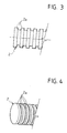
- Figures 3 and 4 illustrate a variant embodiment of the piston, in which the disks 2a alternatively have a different diameter in order to give rise to a segmented conformation of the piston, which may lead to an improvement in the efficiency of the device.
Landscapes
- Engineering & Computer Science (AREA)
- Chemical & Material Sciences (AREA)
- Combustion & Propulsion (AREA)
- Mechanical Engineering (AREA)
- General Engineering & Computer Science (AREA)
- Power Engineering (AREA)
- Reciprocating Pumps (AREA)
- Particle Formation And Scattering Control In Inkjet Printers (AREA)
Applications Claiming Priority (2)
| Application Number | Priority Date | Filing Date | Title |
|---|---|---|---|
| IT2002TO000375A ITTO20020375A1 (it) | 2002-05-07 | 2002-05-07 | ,,microgeneratore di energia elettrica,, |
| ITTO20020375 | 2002-05-07 |
Publications (2)
| Publication Number | Publication Date |
|---|---|
| EP1361349A2 true EP1361349A2 (de) | 2003-11-12 |
| EP1361349A3 EP1361349A3 (de) | 2003-11-26 |
Family
ID=27639048
Family Applications (1)
| Application Number | Title | Priority Date | Filing Date |
|---|---|---|---|
| EP03009128A Withdrawn EP1361349A3 (de) | 2002-05-07 | 2003-04-22 | Mikrostromgenerator |
Country Status (3)
| Country | Link |
|---|---|
| US (1) | US6932030B2 (de) |
| EP (1) | EP1361349A3 (de) |
| IT (1) | ITTO20020375A1 (de) |
Cited By (6)
| Publication number | Priority date | Publication date | Assignee | Title |
|---|---|---|---|---|
| WO2006127500A3 (en) * | 2005-05-23 | 2007-03-08 | Rockwell Scient Co | Multiple magnet moving coil reciprocating generator |
| US7385309B2 (en) | 2004-02-04 | 2008-06-10 | Crf Societa Consortile Per Azioni | Innovative architectures for systems for generation and distribution of energy on board motor vehicles |
| WO2008156897A3 (en) * | 2007-04-05 | 2009-04-09 | Raytheon Sarcos Llc | Rapid-fire rapid-response power conversion system |
| GB2472604A (en) * | 2009-08-12 | 2011-02-16 | Alastair Gordon Laurence Hunter | Free piston thermo electrical power generator |
| CN108494216A (zh) * | 2018-04-17 | 2018-09-04 | 南京理工大学 | 一种后坐-爆炸驱动的双行程直线运动发电机及其发电方法 |
| DE102007052959B4 (de) * | 2007-03-15 | 2018-11-08 | Korea Institute Of Energy Research | Tragbare Stromerzeugungsvorrichtung, Vorrichtung zur Versorgung mit Kraftstoff und Luft für die tragbare Stromerzeugungsvorrichtung, Mikromotor mit Gleichstromspülung für die tragbare Stromerzeugungsvorrichtung |
Families Citing this family (17)
| Publication number | Priority date | Publication date | Assignee | Title |
|---|---|---|---|---|
| WO2004086600A1 (en) * | 2003-03-20 | 2004-10-07 | University Of South Florida | Mems microgenerator cell and microgenerator cell array |
| US8020490B1 (en) | 2003-07-24 | 2011-09-20 | University Of South Florida | Method of fabricating MEMS-based micro detonators |
| GB2412501B (en) * | 2004-03-26 | 2007-10-31 | Univ Southampton | An electromagnetic device for converting mechanical vibrational energy into electrical energy |
| US20060130782A1 (en) * | 2004-12-17 | 2006-06-22 | Boland David V | Engine |
| US20060156719A1 (en) * | 2005-01-19 | 2006-07-20 | Wheeler Roland T | Electrical power generating system |
| US8546680B2 (en) * | 2005-07-08 | 2013-10-01 | Ying Wen Hsu | Energy efficient micro combustion system for power generation and fuel processing |
| US7640910B2 (en) * | 2006-03-16 | 2010-01-05 | Achates Power, Inc | Opposed piston internal-combustion engine with hypocycloidal drive and generator apparatus |
| US7318506B1 (en) * | 2006-09-19 | 2008-01-15 | Vladimir Meic | Free piston engine with linear power generator system |
| DE102006056349A1 (de) * | 2006-11-29 | 2008-06-05 | Gerhard Schilling | Vorrichtung zur Umwandlung thermodynamischer Energie in elektrische Energie |
| US7834777B2 (en) | 2006-12-01 | 2010-11-16 | Baker Hughes Incorporated | Downhole power source |
| US7950356B2 (en) * | 2007-10-09 | 2011-05-31 | The Invention Science Fund I, Llc | Opposed piston electromagnetic engine |
| US7856714B2 (en) * | 2007-10-10 | 2010-12-28 | The Invention Science Fund I, Llc | Method of retrofitting an engine |
| US7622814B2 (en) * | 2007-10-04 | 2009-11-24 | Searete Llc | Electromagnetic engine |
| US7777357B2 (en) * | 2007-10-05 | 2010-08-17 | The Invention Fund I, LLC | Free piston electromagnetic engine |
| WO2009129547A1 (en) * | 2008-04-18 | 2009-10-22 | The Board Of Trustees Of The University Of Alabama | Meso-scaled combustion system |
| US8201523B2 (en) * | 2008-06-27 | 2012-06-19 | Cohen Kenneth J | Integrated combustion and electric hybrid engines and methods of making and use thereof |
| CN103670823B (zh) * | 2013-05-27 | 2016-01-20 | 江苏大学 | 一种进气预加热式微自由活塞发电机 |
Family Cites Families (7)
| Publication number | Priority date | Publication date | Assignee | Title |
|---|---|---|---|---|
| US3105153A (en) * | 1960-08-05 | 1963-09-24 | Exxon Research Engineering Co | Free-piston generator of electric current |
| DE3224723A1 (de) * | 1982-07-02 | 1984-01-05 | Wolfgang 8501 Oberasbach Täuber | Freikolbenbrennkraftmaschine mit generator |
| US5437255A (en) * | 1994-03-15 | 1995-08-01 | Sadley; Mark L. | Fuel injection sytem employing solid-state injectors for liquid fueled combustion engines |
| US6109222A (en) * | 1997-11-24 | 2000-08-29 | Georgia Tech Research Corporation | Miniature reciprocating combustion-driven machinery |
| RU2143343C1 (ru) * | 1998-11-03 | 1999-12-27 | Самсунг Электроникс Ко., Лтд. | Микроинжектор и способ изготовления микроинжектора |
| US6276313B1 (en) * | 1999-12-30 | 2001-08-21 | Honeywell International Inc. | Microcombustion engine/generator |
| IT1320381B1 (it) * | 2000-05-29 | 2003-11-26 | Olivetti Lexikon Spa | Metodo per la fabbricazione di una testina di eiezione di gocce diliquido particolarmente adatta per operare con liquidi chimicamente |
-
2002
- 2002-05-07 IT IT2002TO000375A patent/ITTO20020375A1/it unknown
-
2003
- 2003-04-22 EP EP03009128A patent/EP1361349A3/de not_active Withdrawn
- 2003-05-06 US US10/429,716 patent/US6932030B2/en not_active Expired - Fee Related
Cited By (7)
| Publication number | Priority date | Publication date | Assignee | Title |
|---|---|---|---|---|
| US7385309B2 (en) | 2004-02-04 | 2008-06-10 | Crf Societa Consortile Per Azioni | Innovative architectures for systems for generation and distribution of energy on board motor vehicles |
| WO2006127500A3 (en) * | 2005-05-23 | 2007-03-08 | Rockwell Scient Co | Multiple magnet moving coil reciprocating generator |
| DE102007052959B4 (de) * | 2007-03-15 | 2018-11-08 | Korea Institute Of Energy Research | Tragbare Stromerzeugungsvorrichtung, Vorrichtung zur Versorgung mit Kraftstoff und Luft für die tragbare Stromerzeugungsvorrichtung, Mikromotor mit Gleichstromspülung für die tragbare Stromerzeugungsvorrichtung |
| WO2008156897A3 (en) * | 2007-04-05 | 2009-04-09 | Raytheon Sarcos Llc | Rapid-fire rapid-response power conversion system |
| GB2472604A (en) * | 2009-08-12 | 2011-02-16 | Alastair Gordon Laurence Hunter | Free piston thermo electrical power generator |
| CN108494216A (zh) * | 2018-04-17 | 2018-09-04 | 南京理工大学 | 一种后坐-爆炸驱动的双行程直线运动发电机及其发电方法 |
| CN108494216B (zh) * | 2018-04-17 | 2019-11-15 | 南京理工大学 | 一种后坐-爆炸驱动的双行程直线运动发电机及其发电方法 |
Also Published As
| Publication number | Publication date |
|---|---|
| ITTO20020375A1 (it) | 2003-11-07 |
| ITTO20020375A0 (it) | 2002-05-07 |
| US20040079301A1 (en) | 2004-04-29 |
| EP1361349A3 (de) | 2003-11-26 |
| US6932030B2 (en) | 2005-08-23 |
Similar Documents
| Publication | Publication Date | Title |
|---|---|---|
| US6932030B2 (en) | Microgenerator of electrical energy | |
| US12374696B2 (en) | Integrated fuel cell and combustion system | |
| Yoshida et al. | High-energy density miniature thermoelectric generator using catalytic combustion | |
| JP5161572B2 (ja) | 固体酸化物型燃料電池システム | |
| JP2005043046A (ja) | ハイブリッド燃料電池−パルスデトネーションパワーシステム | |
| KR101332996B1 (ko) | 발전장치 | |
| EP1241339B1 (de) | Verbund-Energieerzeugungssystem | |
| US6127055A (en) | Multi-source electrical drive system | |
| BR9911168B1 (pt) | célula de combustìvel para produção de energia elétrica. | |
| JP2004152645A (ja) | ハニカム構造で構成された固体酸化物燃料電池、および固体酸化物燃料電池における流体供給方法。 | |
| US20070082310A1 (en) | Catalytic microcombustors for compact power or heat generation | |
| JP2004146343A (ja) | 燃料電池および燃料電池スタック | |
| KR100602561B1 (ko) | 연료전지 | |
| KR20100045447A (ko) | 발전장치 | |
| JP2007200710A (ja) | 固体酸化物形燃料電池スタック | |
| JP2009152069A (ja) | 燃料電池スタック | |
| Guo et al. | Heat and mass transfer and two phase flow in hydrogen proton exchange membrane fuel cells and direct methanol fuel cells | |
| CN108049969A (zh) | 一种带有余热利用的微型自由活塞动力装置 | |
| KR102887002B1 (ko) | 열-전기화학 컨버터 | |
| JP2012089508A (ja) | 固体酸化物形燃料電池スタック | |
| AJIE APRILIANTO et al. | THE UTILIZATION OF WASTE HEAT FROM POLYMERIC ELECTROLYTE MEMBRANE FUEL CELLS (PEMFC) USING THERMOELECTRIC GENERATOR (TEG): A REVIEW. | |
| KR20050101350A (ko) | 전기화학 에너지 소스 및 상기 에너지 소스를 포함하는전자 디바이스 | |
| Yingche et al. | Micro-power development and application prospects in fuze | |
| CN117638134A (zh) | 一种航空燃料电池系统以及航空器 | |
| KR20130073370A (ko) | 고체 산화물 연료전지 스택의 성능 최적화를 위한 지지체 구조의 설계 및 이에 의해서 설계된 새로운 구조의 고체 산화물 연료전지 스택 |
Legal Events
| Date | Code | Title | Description |
|---|---|---|---|
| PUAI | Public reference made under article 153(3) epc to a published international application that has entered the european phase |
Free format text: ORIGINAL CODE: 0009012 |
|
| PUAL | Search report despatched |
Free format text: ORIGINAL CODE: 0009013 |
|
| AK | Designated contracting states |
Kind code of ref document: A2 Designated state(s): AT BE BG CH CY CZ DE DK EE ES FI FR GB GR HU IE IT LI LU MC NL PT RO SE SI SK TR |
|
| AX | Request for extension of the european patent |
Extension state: AL LT LV MK |
|
| AK | Designated contracting states |
Kind code of ref document: A3 Designated state(s): AT BE BG CH CY CZ DE DK EE ES FI FR GB GR HU IE IT LI LU MC NL PT RO SE SI SK TR |
|
| AX | Request for extension of the european patent |
Extension state: AL LT LV MK |
|
| RIC1 | Information provided on ipc code assigned before grant |
Ipc: 7F 02B 1/12 B Ipc: 7H 02K 7/18 B Ipc: 7F 02B 75/34 B Ipc: 7F 02B 63/04 B Ipc: 7F 02B 71/04 A |
|
| 17P | Request for examination filed |
Effective date: 20031111 |
|
| 17Q | First examination report despatched |
Effective date: 20040115 |
|
| AKX | Designation fees paid |
Designated state(s): AT BE BG CH CY CZ DE DK EE ES FI FR GB GR HU IE IT LI LU MC NL PT RO SE SI SK TR |
|
| STAA | Information on the status of an ep patent application or granted ep patent |
Free format text: STATUS: THE APPLICATION IS DEEMED TO BE WITHDRAWN |
|
| 18D | Application deemed to be withdrawn |
Effective date: 20051001 |