EP1361337A1 - Kühlkonfiguration für ein Turbomaschinenschaufelblatt - Google Patents
Kühlkonfiguration für ein Turbomaschinenschaufelblatt Download PDFInfo
- Publication number
- EP1361337A1 EP1361337A1 EP02253252A EP02253252A EP1361337A1 EP 1361337 A1 EP1361337 A1 EP 1361337A1 EP 02253252 A EP02253252 A EP 02253252A EP 02253252 A EP02253252 A EP 02253252A EP 1361337 A1 EP1361337 A1 EP 1361337A1
- Authority
- EP
- European Patent Office
- Prior art keywords
- airfoil
- cooling
- root
- radially
- extending
- Prior art date
- Legal status (The legal status is an assumption and is not a legal conclusion. Google has not performed a legal analysis and makes no representation as to the accuracy of the status listed.)
- Granted
Links
Images


Classifications
-
- F—MECHANICAL ENGINEERING; LIGHTING; HEATING; WEAPONS; BLASTING
- F01—MACHINES OR ENGINES IN GENERAL; ENGINE PLANTS IN GENERAL; STEAM ENGINES
- F01D—NON-POSITIVE DISPLACEMENT MACHINES OR ENGINES, e.g. STEAM TURBINES
- F01D5/00—Blades; Blade-carrying members; Heating, heat-insulating, cooling or antivibration means on the blades or the members
- F01D5/12—Blades
- F01D5/14—Form or construction
- F01D5/18—Hollow blades, i.e. blades with cooling or heating channels or cavities; Heating, heat-insulating or cooling means on blades
- F01D5/187—Convection cooling
-
- F—MECHANICAL ENGINEERING; LIGHTING; HEATING; WEAPONS; BLASTING
- F05—INDEXING SCHEMES RELATING TO ENGINES OR PUMPS IN VARIOUS SUBCLASSES OF CLASSES F01-F04
- F05D—INDEXING SCHEME FOR ASPECTS RELATING TO NON-POSITIVE-DISPLACEMENT MACHINES OR ENGINES, GAS-TURBINES OR JET-PROPULSION PLANTS
- F05D2260/00—Function
- F05D2260/20—Heat transfer, e.g. cooling
- F05D2260/201—Heat transfer, e.g. cooling by impingement of a fluid
-
- Y—GENERAL TAGGING OF NEW TECHNOLOGICAL DEVELOPMENTS; GENERAL TAGGING OF CROSS-SECTIONAL TECHNOLOGIES SPANNING OVER SEVERAL SECTIONS OF THE IPC; TECHNICAL SUBJECTS COVERED BY FORMER USPC CROSS-REFERENCE ART COLLECTIONS [XRACs] AND DIGESTS
- Y02—TECHNOLOGIES OR APPLICATIONS FOR MITIGATION OR ADAPTATION AGAINST CLIMATE CHANGE
- Y02T—CLIMATE CHANGE MITIGATION TECHNOLOGIES RELATED TO TRANSPORTATION
- Y02T50/00—Aeronautics or air transport
- Y02T50/60—Efficient propulsion technologies, e.g. for aircraft
Definitions
- the present invention relates generally to cooling air circuits of turbine rotor blades and stator vanes in gas turbine engines and, more specifically, to metering plates at the base of roots used to meter flow to the cooling circuits within airfoils of the blades and vanes.
- a gas turbine engine includes a compressor that compresses air which is channeled to a combustor wherein it is mixed with fuel and ignited for generating combustion gases.
- the combustion gases flow downstream through one or more stages of turbines which extract energy therefrom for powering the compressor and producing additional output power for driving a fan for powering an aircraft in flight for example.
- a turbine stage includes a row of turbine rotor blades secured to the outer perimeter of a rotor disk with a stationary turbine nozzle having a plurality of stator vanes disposed upstream therefrom.
- the combustion gases flow between the stator vanes and between the turbine blades for extracting energy to rotate the rotor disk.
- the temperatures within gas turbines may exceed 2500 degrees Fahrenheit and cooling of turbine blades is very important in terms of blade longevity.
- Typical turbine vanes and blades include an airfoil over which the combustion gases flow.
- the airfoil typically, includes one or more serpentine cooling passages therein through which cooling air from compressor bleed air is channeled for cooling the airfoil.
- the airfoil may include various turbulators therein for enhancing cooling effectiveness and the cooling air is discharged from the passages through various film cooling holes disposed around the outer surface of the airfoil.
- backflow margin As air flow travels through the internal passages of the blade, pressure losses due to turns and turbulence promoters cause the cooling flow pressure to drop to a level, such that under certain operating conditions, hot gas ingestion into the blade leading edge may occur. This undesired condition is referred to as backflow.
- One approach for providing more backflow margin is to increase the inlet pressure of the cooling air which is supplied to the blade. This approach is not always feasible because the increase in supply pressure can increase cooling flow leakages to an undesired level.
- leading edge flow passages supplying cooling air for impingement were supplied with refresher passageways. The refresher passageway is connected to a portion of a first channel of the cooling circuit in the root of the blade.
- This circuit supplies impingement cooling air to the leading edge cavity from its last channel referred to herein as a leading edge supply channel.
- the refresher passageway refreshes the airflow in this last channel after the airflow has flowed through the rest of the circuit and has become warmed. See United States Patent Nos. 5,387,086 and 5,813,826.
- the refresher passageway to the leading edge supply channel is connected to the serpentine cooling circuit inlet channel which passes through the root of the blade and, thus, is coupled to the flow rate through the serpentine cooling circuit. It is desirable to be able to tune the cooling flow through the refresher passageway independent of the flow through the serpentine cooling circuit in order to adjust the flow and pressure to the leading edge supply channel. This would be particularly useful if a blade casting is produced which has higher than desired pressure drops through the serpentine passages or impingement holes. This is also desirable for adjustments to the blade cooling circuit that are useful or necessary due to blade hole and serpentine circuit deterioration such as may be caused by blockages and wear.
- Known turbine airfoil cooling techniques include the use of internal cavities forming a serpentine cooling circuit. Particularly, serpentine passages, leading edge impingement bridges, turbulence promoters and turbulators, film holes, pin fins, and trailing edge holes or pressure side bleed slots are utilized for blade cooling. It is desirable to provide improved blade cooling. In providing even better blade cooling, it is also desirable to avoid significantly increasing the blade fabrication costs.
- a gas turbine engine hollow airfoil has an airfoil outer wall with widthwise spaced apart pressure and suction side walls joined together at chordally spaced apart leading and trailing edges of the airfoil and extending radially from a radially inner base to a radially outer airfoil tip.
- a cooling circuit within the airfoil has radially extending first, middle, and last channels arranged respectively in series with the first channel in fluid communication with a source of cooling air from outside the airfoil. The last channel is in fluid communication with one of the edges.
- a refresher passageway extends through a radially inner wall bounding a radially inner portion of the last channel and is in fluid communication with the source of cooling air. The refresher passageway is separate, spaced apart, and independent from the first channel.
- One exemplary embodiment of the invention further includes an edge cooling plenum located between the last channel and one of the edges and cooling air discharge apertures disposed through a radially extending rib between the last channel and the edge cooling plenum.
- the edge cooling plenum may be a leading edge cooling plenum and the cooling air discharge apertures may be impingement cooling holes and may also include leading edge cooling holes leading out of the edge cooling plenum through the outer wall around the leading edge.
- the last channel is bounded by the trailing edge and cooling air discharge apertures are disposed through the trailing edge and may be trailing edge cooling slots.
- Exemplary embodiments of the invention may further include a metering plate covering an inlet to the refresher passageway and the metering plate has a metering hole over the inlet and the metering hole is adjustable.
- Another exemplary embodiment of the invention is a gas turbine engine blade with the hollow airfoil extending radially outwardly from a root.
- the first channel extends through the root and has an entrance at a bottom surface of the root.
- the refresher passageway extends through a radially inner wall bounding a radially inner portion of the last channel and through the root.
- the inlet to the refresher passageway is located at the bottom surface of the root and is separate and spaced apart from the entrance of the first channel.
- the metering plate is disposed on the bottom surface of the root.
- a forward flowing serpentine cooling circuit and an aft flowing serpentine cooling circuit are located within the airfoil.
- Each of the cooling circuits has the radially extending first, middle, and last channels arranged respectively in series and each of the first channels extend through the root and have an entrance at a bottom surface of the root.
- the last channel of the forward flowing serpentine cooling circuit is in fluid communication with the leading edge and the last channel of the aft flowing serpentine cooling circuit is in fluid communication with the trailing edge.
- Forward and aft refresher passageways extend through forward and aft radially inner walls bounding radially inner portions of the forward and aft last channels, respectively, and through the root.
- the refresher passageways have inlets at the bottom surface of the root and the inlets are separate and spaced apart from the entrances.
- the cooling circuit configuration of the present invention allows the use of a lower coolant supply pressure.
- the three pass serpentine is also less vulnerable to variations in pressure drops from cast features than the circuits having more channels and passes.
- Dedicated circuits or channels for leading edge and trailing edge cooling provide better internal cooling at the edges where the external heat load is highest.
- the refresher passageways mix in cooler air for the benefit of the edges and, thus, reduce the amount of cooling that has to go through the serpentine cooling circuits and incur flow losses due to friction and turning.
- the refresher passageways allow a lighter design with less cavities for cooling to be practical at higher turbine temperatures than before.
- the present invention allows weight reduction of the airfoil and blade and more cooling flow to be used at the leading and trailing edges.
- the invention can also help protect against airfoil and blade failure due to foreign object damage, a hard rub, or other cause which results in a hole in a serpentine at a tip turn.
- Other circuits will lose the coolant out the hole and starve the rest of the serpentine cooling circuit.
- the refresher passageways will provide flow at the root of each cavity to reduce the thermal distress due to loss of coolant from the serpentine circuit.
- the airfoil and blade design of the present invention increases producibility and production yield because the refresher holes can be tuned to provide more flow and pressure to the edges if a casting comes which has higher than desired pressure drops in the serpentine circuit or impingement holes. Prior art designs the situation would require scrapping parts and waiting for a casting core die rework.
- the present invention provides metering plates that are adjustable and, therefore, can be used to adjust amount of cooling flow to the edges.
- the metering plate with a metering hole, which may be brazed over the inlet to the refresher passageway allows for a sturdy core during casting, a light weight shank, and adjustable metering of the refresher flow.
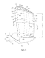
- FIG. 1 Illustrated in FIG. 1 is an exemplary turbine blade 10 for a gas turbine engine designed to be operated in a hot gas stream that flows in an axial flow downstream direction F.
- the blade 10 includes a hollow airfoil 12 extending radially outwardly from a root 14.
- the root 14 is used to secure the blade 10 to a rotor disk (not shown) of the engine which is circumscribed about an engine centerline 11.
- the airfoil 12 includes an outer wall 15 widthwise or transversely spaced apart pressure and suction side walls 16 and 18, respectively, joined together along an upstream leading edge 20 and a downstream trailing edge 22 which is spaced chordally apart from the leading edge.
- the airfoil 12 extends radially in a radial direction 24 away from the engine centerline 11 in a spanwise direction of the airfoil 12 from a radially inner base 26 to a radially outer airfoil tip 28 along a span S of the airfoil.
- the airfoil tip 28 is illustrated as a squealer tip having an outward extension from the outer wall 15 or a squealer wall 29 extending radially outward from and peripherally around an outer tip wall 31 forming a squealer tip cavity 33 therein.
- Tip cooling holes 59 extending through the outer tip wall 31 from within the hollow airfoil 12 to the squealer tip cavity 33 are used to cool the tip cavity.
- the radially inner base 26 is defined at a conventional platform 30 which forms the inner flow boundary of the blade 10 and below which extends the root 14.
- combustion gases 32 are generated by a combustor (not shown) and flow downstream over both airfoil pressure and suction side walls 16 and 18, respectively, of the outer wall 15.
- the exemplary embodiment of the present invention illustrated herein is designed to effect efficient cooling of the airfoil 12 to better match the distribution of the heat load thereto from the combustion gases 32.
- the gas turbine blade 10 illustrated in FIGS. 1-3 is exemplary and the invention applies equally as well to turbine stator vanes having similar airfoils which may be similarly cooled.
- the hollow airfoil 12 is illustrated in cross-section with the outer wall 15 and the pressure and suction side walls 16 and 18, respectively, spaced circumferentially or laterally apart from each other between the leading and trailing edges 20 and 22.
- the pressure and suction side walls 16 and 18 are integrally joined together by a plurality of internal transverse ribs indicated generally at 34 which extend between the pressure and suction side walls 16 and 18, respectively.
- First, second, third, and fourth ribs 1-4, respectively, of the transverse ribs 34 define a single forward flowing three pass serpentine cooling circuit 36 as illustrated in FIG. 3.
- the fourth rib 4, fifth and sixth ribs 5 and 6, and the trailing edge 22 define a single aft flowing three pass serpentine cooling circuit 38.
- FIG. 3 illustrates the airfoil 12 laid out flat along a cooling circuit split-line 46 in FIG. 2 that passes through the forward and aft flowing serpentine cooling circuits 36 and 38.
- the forward flowing serpentine cooling circuit 36 is constructed so as to cause a serpentine cooling flow 35 within the cooling circuit 36 to flow in a forward chordal flow direction 45, forwards from the trailing edge 22 to the leading edge 20 within the forward flowing serpentine cooling circuit 36.
- the forward flowing cooling circuit 36 includes an entrance 37 at a bottom surface 49 of the root 14 and is positioned aft of a terminal end 39 of the forward flowing cooling circuit to cause the serpentine cooling flow 35 to flow in the forward chordal flow direction 45 forwards from the trailing edge 22 to the leading edge 20.
- the aft flowing serpentine cooling circuit 38 is constructed so as to cause the serpentine cooling flow 35 within the aft flowing serpentine cooling circuit 38 to flow in an aft chordal flow direction 43 afterwards from the leading edge 20 to the trailing edge 22 within the aft flowing serpentine cooling circuit 38.
- the aft flowing serpentine cooling circuit 38 includes an entrance 37 in the bottom surface 49 of root 14 and is positioned forward of a terminal end 39 of the aft flowing serpentine cooling circuit to cause the serpentine cooling flow 35 to flow in the aft chordal flow direction 43 afterwards from the leading edge 20 to the trailing edge 22. This is to better match the applied heat loads from the combustion gases 32 and to more effectively tailor the serpentine cooling flows 35 to the heat loading of the airfoil 12 and more effectively cool the airfoil.
- the forward and aft flowing serpentine cooling circuits 36 and 38 are referred to as a three pass circuit because they each have three radially extending channels denoted as first, middle, and last cooling channels 40, 41, and 42.
- the invention may have more than the one middle channel as illustrated in the exemplary embodiment herein.
- the first, middle, and last cooling channels 40, 41, and 42 of the forward flowing serpentine cooling circuit 36 are defined by and disposed between the chordally spaced apart internal ribs 34 denoted as the first through fourth ribs 1-4, respectively, in FIG. 3 and bounded on their transverse sides 47 (illustrated in FIG. 2) by the pressure side and suction side walls 16 and 18.
- the first channels 40 of the forward and aft flowing serpentine cooling circuits 36 and 38 extend radially through the base 26 of the airfoil 12 and through the root 14 of the blade 10 and radially upwardly to radially outer first turning channels 50.
- the first channels 40 of the forward and aft flowing serpentine cooling circuits 36 and 38 begin at the entrances 37 in the bottom surface 49 of the root 14 of the airfoil 12.
- the first turning channels 50 turn the cooling air radially inwardly into the middle cooling channel 41 (or if more than one then middle cooling channels) which direct the cooling air radially inwardly to radially inner second turning channels 52, which in turn, direct the cooling air radially upwardly into the last cooling channels 42.
- the last cooling channels 42 and the forward and aft flowing serpentine cooling circuits 36 and 38 terminate at the outer tip wall 31 where one or more of the tip cooling holes 59 may be used to vent the serpentine cooling circuits.
- the airfoil squealer tip is cooled by the tip cooling hole 59 in the outer tip wall 31.
- the placement of the tip cooling holes 59 in radially outer ends of one or more of the first, middle, and/or last cooling channels 40, 41, and 42 permits better control and metering of cooling air to the squealer type airfoil tip 28.
- a leading edge cooling plenum 72 is located between the leading edge 20 of the outer wall 15 and the first rib 1.
- Discharge apertures which in the exemplary embodiment function, are impingement cooling holes 74, are disposed and extend through the first rib 1 from the last channel 42 of the forward flowing serpentine cooling circuit 36 to the leading edge cooling plenum 72.
- the impingement cooling holes 74 feed cooling air from the last channel 42 of the forward flowing serpentine cooling circuit 36 to the leading edge cooling plenum 72 from where it is flowed through film cooling holes.
- the film cooling holes include one or more of the following: shower head, pressure side wall, and suction side wall film cooling holes 60, 62, and 64, respectively.
- the trailing edge 22 is cooled by cooling air passed through discharge apertures in the form of trailing edge cooling slots 76 designed to provide convective cooling of the trailing edge 22. These two arrangements are used to cool the leading and trailing edges 20 and 22, respectively.
- Refresher passageways 66 extend through radially inner walls bounding radially inner portions 70 of said last channels 42 of the forward and aft flowing serpentine cooling circuits 36 and 38.
- the refresher passageways 66 extend all the way through the root 14 and are in fluid communication with a source of cooling air outside the airfoil 12 and the refresher passageways 66 operate independent and separate from the forward and aft flowing serpentine cooling circuits 36 and 38.
- the refresher passageways 66 have inlets 68 in the bottom surface 49 of the root 14 and the inlets are spaced apart from the entrances 37 of the forward and aft flowing serpentine cooling circuits 36 and 38.
- Two metering plates 80 are disposed on the bottom surface 49 of the root 14 and each one covers one of the inlets 68 to the refresher passageways 66.
- Each of the metering plates has a metering hole 82 centered over the inlet.
- the metering plates are adjustable and therefore can be used to adjust amount of cooling flow to the edges. The adjustability is provided by opening up the hole by increasing its diameter or area or by using plates with different hole sizes.
- the metering plate 80 may be brazed over the inlet 68 to the refresher passageway 66 after the casting is completed and blade or airfoil has been tested for flow.
- the independent refresher passageways and metering plate allows for a sturdy core during casting, a light weight shank, and adjustable metering of the refresher flow.
- FIG. 2 Illustrated in FIG. 2 is a cross-section of the exemplary airfoil illustrated herein.
- the forward flowing serpentine cooling circuit 36 is illustrated as having no film cooling holes while the aft flowing serpentine cooling circuit 38 is illustrated as having pressure side wall film cooling holes 62 in the first, middle, and last cooling channels 40, 41, and 42.
- the pressure side wall film cooling holes 62 are disposed through the outer wall 15 along the pressure side wall 16 of the outer wall 15 along the aft flowing serpentine cooling circuit 38.
- the film cooling holes are compound angled downstream and radially outward with respect to the engine centerline 11 and leading out from channels and the leading edge cooling plenum 72 through the outer wall 15. Film cooling holes may be placed along both the pressure and suction side walls 16 and 18, respectively, of the outer wall 15.
- the airfoil 12 may have any other conventional features for enhancing the cooling thereof such as turbulators or pins (not shown) which are well known in the art.
- Thermal barrier coatings TBC well known in the technology, may also be used to improve thermal characteristics of the airfoil 12.
- the invention has been described with respect to the exemplary turbine blade 10 illustrated in the FIGS., it may also be used for turbine nozzle vanes which have similar airfoils which can benefit from preferential spanwise cooling thereof for better matching the radial applied temperature distribution from the combustion gases 32.
- the forward and aft flowing serpentine cooling circuit airfoils and blades may be readily manufactured using conventional casting techniques as are used for conventional multi-pass serpentine passages.
Priority Applications (2)
| Application Number | Priority Date | Filing Date | Title |
|---|---|---|---|
| EP02253252A EP1361337B1 (de) | 2002-05-09 | 2002-05-09 | Kühlkonfiguration für ein Turbomaschinenschaufelblatt |
| DE60217071T DE60217071T2 (de) | 2002-05-09 | 2002-05-09 | Kühlkonfiguration für ein Turbomaschinenschaufelblatt |
Applications Claiming Priority (1)
| Application Number | Priority Date | Filing Date | Title |
|---|---|---|---|
| EP02253252A EP1361337B1 (de) | 2002-05-09 | 2002-05-09 | Kühlkonfiguration für ein Turbomaschinenschaufelblatt |
Publications (2)
| Publication Number | Publication Date |
|---|---|
| EP1361337A1 true EP1361337A1 (de) | 2003-11-12 |
| EP1361337B1 EP1361337B1 (de) | 2006-12-27 |
Family
ID=29225731
Family Applications (1)
| Application Number | Title | Priority Date | Filing Date |
|---|---|---|---|
| EP02253252A Revoked EP1361337B1 (de) | 2002-05-09 | 2002-05-09 | Kühlkonfiguration für ein Turbomaschinenschaufelblatt |
Country Status (2)
| Country | Link |
|---|---|
| EP (1) | EP1361337B1 (de) |
| DE (1) | DE60217071T2 (de) |
Cited By (9)
| Publication number | Priority date | Publication date | Assignee | Title |
|---|---|---|---|---|
| US7153096B2 (en) | 2004-12-02 | 2006-12-26 | Siemens Power Generation, Inc. | Stacked laminate CMC turbine vane |
| US7198458B2 (en) | 2004-12-02 | 2007-04-03 | Siemens Power Generation, Inc. | Fail safe cooling system for turbine vanes |
| US7255535B2 (en) | 2004-12-02 | 2007-08-14 | Albrecht Harry A | Cooling systems for stacked laminate CMC vane |
| EP1923537A2 (de) * | 2006-11-20 | 2008-05-21 | General Electric Company | Doppelte Kühlluftversorgung der Serpentine einer gekühlten Schaufel |
| EP2025872A2 (de) * | 2007-08-08 | 2009-02-18 | Snecma | Verteilersektor einer Turbine |
| WO2017005781A1 (en) * | 2015-07-06 | 2017-01-12 | Siemens Aktiengesellschaft | Turbine stator vane and/or turbine rotor vane with a cooling flow adjustment feature and corresponding method of adapting a vane |
| CN107989658A (zh) * | 2016-10-26 | 2018-05-04 | 通用电气公司 | 用于多壁叶片的冷却回路 |
| US11814965B2 (en) | 2021-11-10 | 2023-11-14 | General Electric Company | Turbomachine blade trailing edge cooling circuit with turn passage having set of obstructions |
| WO2023223741A1 (ja) * | 2022-05-20 | 2023-11-23 | 三菱重工業株式会社 | タービン翼及びガスタービン |
Citations (6)
| Publication number | Priority date | Publication date | Assignee | Title |
|---|---|---|---|---|
| US3533711A (en) * | 1966-02-26 | 1970-10-13 | Gen Electric | Cooled vane structure for high temperature turbines |
| US4278400A (en) * | 1978-09-05 | 1981-07-14 | United Technologies Corporation | Coolable rotor blade |
| JPS60198305A (ja) * | 1984-03-23 | 1985-10-07 | Agency Of Ind Science & Technol | ガスタ−ビン動翼の冷却構造 |
| GB2250548A (en) * | 1990-12-06 | 1992-06-10 | Rolls Royce Plc | Cooled turbine aerofoil blade |
| US5975850A (en) * | 1996-12-23 | 1999-11-02 | General Electric Company | Turbulated cooling passages for turbine blades |
| US20020119045A1 (en) * | 2001-02-23 | 2002-08-29 | Starkweather John Howard | Turbine airfoil with metering plates for refresher holes |
-
2002
- 2002-05-09 EP EP02253252A patent/EP1361337B1/de not_active Revoked
- 2002-05-09 DE DE60217071T patent/DE60217071T2/de not_active Expired - Lifetime
Patent Citations (6)
| Publication number | Priority date | Publication date | Assignee | Title |
|---|---|---|---|---|
| US3533711A (en) * | 1966-02-26 | 1970-10-13 | Gen Electric | Cooled vane structure for high temperature turbines |
| US4278400A (en) * | 1978-09-05 | 1981-07-14 | United Technologies Corporation | Coolable rotor blade |
| JPS60198305A (ja) * | 1984-03-23 | 1985-10-07 | Agency Of Ind Science & Technol | ガスタ−ビン動翼の冷却構造 |
| GB2250548A (en) * | 1990-12-06 | 1992-06-10 | Rolls Royce Plc | Cooled turbine aerofoil blade |
| US5975850A (en) * | 1996-12-23 | 1999-11-02 | General Electric Company | Turbulated cooling passages for turbine blades |
| US20020119045A1 (en) * | 2001-02-23 | 2002-08-29 | Starkweather John Howard | Turbine airfoil with metering plates for refresher holes |
Non-Patent Citations (1)
| Title |
|---|
| PATENT ABSTRACTS OF JAPAN vol. 010, no. 047 (M - 456) 25 February 1986 (1986-02-25) * |
Cited By (16)
| Publication number | Priority date | Publication date | Assignee | Title |
|---|---|---|---|---|
| US7198458B2 (en) | 2004-12-02 | 2007-04-03 | Siemens Power Generation, Inc. | Fail safe cooling system for turbine vanes |
| US7255535B2 (en) | 2004-12-02 | 2007-08-14 | Albrecht Harry A | Cooling systems for stacked laminate CMC vane |
| US7153096B2 (en) | 2004-12-02 | 2006-12-26 | Siemens Power Generation, Inc. | Stacked laminate CMC turbine vane |
| US8591189B2 (en) | 2006-11-20 | 2013-11-26 | General Electric Company | Bifeed serpentine cooled blade |
| EP1923537A2 (de) * | 2006-11-20 | 2008-05-21 | General Electric Company | Doppelte Kühlluftversorgung der Serpentine einer gekühlten Schaufel |
| EP1923537B1 (de) | 2006-11-20 | 2016-07-13 | General Electric Company | Doppelte Kühlluftversorgung der Serpentine einer gekühlten Schaufel |
| EP1923537A3 (de) * | 2006-11-20 | 2012-11-28 | General Electric Company | Doppelte Kühlluftversorgung der Serpentine einer gekühlten Schaufel |
| EP2025872A2 (de) * | 2007-08-08 | 2009-02-18 | Snecma | Verteilersektor einer Turbine |
| EP2025872A3 (de) * | 2007-08-08 | 2011-04-20 | Snecma | Verteilersektor einer Turbine |
| WO2017005781A1 (en) * | 2015-07-06 | 2017-01-12 | Siemens Aktiengesellschaft | Turbine stator vane and/or turbine rotor vane with a cooling flow adjustment feature and corresponding method of adapting a vane |
| CN107849925A (zh) * | 2015-07-06 | 2018-03-27 | 西门子股份公司 | 具有冷却流量调节特征的涡轮机定子叶片和/或涡轮机转子叶片以及适应叶片的对应方法 |
| US10669859B2 (en) | 2015-07-06 | 2020-06-02 | Siemens Aktiengesellschaft | Turbine stator vane and/or turbine rotor vane with a cooling flow adjustment feature and corresponding method of adapting a vane |
| CN107989658A (zh) * | 2016-10-26 | 2018-05-04 | 通用电气公司 | 用于多壁叶片的冷却回路 |
| CN107989658B (zh) * | 2016-10-26 | 2022-08-23 | 通用电气公司 | 用于多壁叶片的冷却回路 |
| US11814965B2 (en) | 2021-11-10 | 2023-11-14 | General Electric Company | Turbomachine blade trailing edge cooling circuit with turn passage having set of obstructions |
| WO2023223741A1 (ja) * | 2022-05-20 | 2023-11-23 | 三菱重工業株式会社 | タービン翼及びガスタービン |
Also Published As
| Publication number | Publication date |
|---|---|
| EP1361337B1 (de) | 2006-12-27 |
| DE60217071D1 (de) | 2007-02-08 |
| DE60217071T2 (de) | 2007-07-12 |
Similar Documents
| Publication | Publication Date | Title |
|---|---|---|
| US6491496B2 (en) | Turbine airfoil with metering plates for refresher holes | |
| EP1008724B1 (de) | Schaufel eines Gasturbinentriebwerks | |
| US7008179B2 (en) | Turbine blade frequency tuned pin bank | |
| JP4486216B2 (ja) | 翼形部の隔離前縁冷却 | |
| US6471479B2 (en) | Turbine airfoil with single aft flowing three pass serpentine cooling circuit | |
| US6220817B1 (en) | AFT flowing multi-tier airfoil cooling circuit | |
| EP1001137B1 (de) | Gasturbinenschaufel mit serpentinenförmigen Kühlkanälen | |
| US7695247B1 (en) | Turbine blade platform with near-wall cooling | |
| US6290463B1 (en) | Slotted impingement cooling of airfoil leading edge | |
| US7527475B1 (en) | Turbine blade with a near-wall cooling circuit | |
| US7442008B2 (en) | Cooled gas turbine aerofoil | |
| US8172533B2 (en) | Turbine blade internal cooling configuration | |
| US7458778B1 (en) | Turbine airfoil with a bifurcated counter flow serpentine path | |
| US5690473A (en) | Turbine blade having transpiration strip cooling and method of manufacture | |
| US5591007A (en) | Multi-tier turbine airfoil | |
| JP4659206B2 (ja) | 勾配付きフイルム冷却を備えるタービンノズル | |
| US6746209B2 (en) | Methods and apparatus for cooling gas turbine engine nozzle assemblies | |
| CA2809000C (en) | Dual-use of cooling air for turbine vane and method | |
| US9388699B2 (en) | Crossover cooled airfoil trailing edge | |
| US5695322A (en) | Turbine blade having restart turbulators | |
| US10830057B2 (en) | Airfoil with tip rail cooling | |
| US7481622B1 (en) | Turbine airfoil with a serpentine flow path | |
| EP1361337B1 (de) | Kühlkonfiguration für ein Turbomaschinenschaufelblatt | |
| CN110494628B (zh) | 具有与冲击平台冷却相集成的翼型部冷却的涡轮机转子叶片 | |
| JP4137508B2 (ja) | リフレッシュ用孔のメータリング板を備えるタービン翼形部 |
Legal Events
| Date | Code | Title | Description |
|---|---|---|---|
| PUAI | Public reference made under article 153(3) epc to a published international application that has entered the european phase |
Free format text: ORIGINAL CODE: 0009012 |
|
| AK | Designated contracting states |
Kind code of ref document: A1 Designated state(s): AT BE CH CY DE DK ES FI FR GB GR IE IT LI LU MC NL PT SE TR |
|
| AX | Request for extension of the european patent |
Extension state: AL LT LV MK RO SI |
|
| 17P | Request for examination filed |
Effective date: 20040512 |
|
| AKX | Designation fees paid |
Designated state(s): DE FR GB IT |
|
| GRAP | Despatch of communication of intention to grant a patent |
Free format text: ORIGINAL CODE: EPIDOSNIGR1 |
|
| GRAS | Grant fee paid |
Free format text: ORIGINAL CODE: EPIDOSNIGR3 |
|
| GRAA | (expected) grant |
Free format text: ORIGINAL CODE: 0009210 |
|
| AK | Designated contracting states |
Kind code of ref document: B1 Designated state(s): DE FR GB IT |
|
| REG | Reference to a national code |
Ref country code: GB Ref legal event code: FG4D |
|
| REF | Corresponds to: |
Ref document number: 60217071 Country of ref document: DE Date of ref document: 20070208 Kind code of ref document: P |
|
| ET | Fr: translation filed | ||
| PLBI | Opposition filed |
Free format text: ORIGINAL CODE: 0009260 |
|
| PLAZ | Examination of admissibility of opposition: despatch of communication + time limit |
Free format text: ORIGINAL CODE: EPIDOSNOPE2 |
|
| 26 | Opposition filed |
Opponent name: ALSTOM TECHNOLOGY LTD. Effective date: 20070926 |
|
| PLAX | Notice of opposition and request to file observation + time limit sent |
Free format text: ORIGINAL CODE: EPIDOSNOBS2 |
|
| PLBA | Examination of admissibility of opposition: reply received |
Free format text: ORIGINAL CODE: EPIDOSNOPE4 |
|
| PLAB | Opposition data, opponent's data or that of the opponent's representative modified |
Free format text: ORIGINAL CODE: 0009299OPPO |
|
| R26 | Opposition filed (corrected) |
Opponent name: ALSTOM TECHNOLOGY LTD Effective date: 20070926 |
|
| PLAF | Information modified related to communication of a notice of opposition and request to file observations + time limit |
Free format text: ORIGINAL CODE: EPIDOSCOBS2 |
|
| PLBB | Reply of patent proprietor to notice(s) of opposition received |
Free format text: ORIGINAL CODE: EPIDOSNOBS3 |
|
| RDAF | Communication despatched that patent is revoked |
Free format text: ORIGINAL CODE: EPIDOSNREV1 |
|
| RDAD | Information modified related to despatch of communication that patent is revoked |
Free format text: ORIGINAL CODE: EPIDOSCREV1 |
|
| APAH | Appeal reference modified |
Free format text: ORIGINAL CODE: EPIDOSCREFNO |
|
| APBM | Appeal reference recorded |
Free format text: ORIGINAL CODE: EPIDOSNREFNO |
|
| APBP | Date of receipt of notice of appeal recorded |
Free format text: ORIGINAL CODE: EPIDOSNNOA2O |
|
| APBQ | Date of receipt of statement of grounds of appeal recorded |
Free format text: ORIGINAL CODE: EPIDOSNNOA3O |
|
| PGFP | Annual fee paid to national office [announced via postgrant information from national office to epo] |
Ref country code: DE Payment date: 20120529 Year of fee payment: 11 |
|
| PGFP | Annual fee paid to national office [announced via postgrant information from national office to epo] |
Ref country code: FR Payment date: 20120607 Year of fee payment: 11 Ref country code: GB Payment date: 20120525 Year of fee payment: 11 |
|
| REG | Reference to a national code |
Ref country code: DE Ref legal event code: R103 Ref document number: 60217071 Country of ref document: DE Ref country code: DE Ref legal event code: R064 Ref document number: 60217071 Country of ref document: DE |
|
| APBU | Appeal procedure closed |
Free format text: ORIGINAL CODE: EPIDOSNNOA9O |
|
| RDAG | Patent revoked |
Free format text: ORIGINAL CODE: 0009271 |
|
| STAA | Information on the status of an ep patent application or granted ep patent |
Free format text: STATUS: PATENT REVOKED |
|
| 27W | Patent revoked |
Effective date: 20130108 |
|
| GBPR | Gb: patent revoked under art. 102 of the ep convention designating the uk as contracting state |
Effective date: 20130108 |
|
| REG | Reference to a national code |
Ref country code: DE Ref legal event code: R107 Ref document number: 60217071 Country of ref document: DE Effective date: 20130404 |
|
| PGFP | Annual fee paid to national office [announced via postgrant information from national office to epo] |
Ref country code: IT Payment date: 20130523 Year of fee payment: 12 |