EP1361086A2 - Active toe angle adjustment mechanism - Google Patents
Active toe angle adjustment mechanism Download PDFInfo
- Publication number
- EP1361086A2 EP1361086A2 EP03004028A EP03004028A EP1361086A2 EP 1361086 A2 EP1361086 A2 EP 1361086A2 EP 03004028 A EP03004028 A EP 03004028A EP 03004028 A EP03004028 A EP 03004028A EP 1361086 A2 EP1361086 A2 EP 1361086A2
- Authority
- EP
- European Patent Office
- Prior art keywords
- linear actuator
- lead screw
- electrical
- electrical linear
- housing
- Prior art date
- Legal status (The legal status is an assumption and is not a legal conclusion. Google has not performed a legal analysis and makes no representation as to the accuracy of the status listed.)
- Granted
Links
Images


Classifications
-
- B—PERFORMING OPERATIONS; TRANSPORTING
- B62—LAND VEHICLES FOR TRAVELLING OTHERWISE THAN ON RAILS
- B62D—MOTOR VEHICLES; TRAILERS
- B62D17/00—Means on vehicles for adjusting camber, castor, or toe-in
-
- B—PERFORMING OPERATIONS; TRANSPORTING
- B60—VEHICLES IN GENERAL
- B60G—VEHICLE SUSPENSION ARRANGEMENTS
- B60G7/00—Pivoted suspension arms; Accessories thereof
- B60G7/001—Suspension arms, e.g. constructional features
- B60G7/003—Suspension arms, e.g. constructional features of adjustable length
-
- B—PERFORMING OPERATIONS; TRANSPORTING
- B60—VEHICLES IN GENERAL
- B60G—VEHICLE SUSPENSION ARRANGEMENTS
- B60G2200/00—Indexing codes relating to suspension types
- B60G2200/10—Independent suspensions
-
- B—PERFORMING OPERATIONS; TRANSPORTING
- B60—VEHICLES IN GENERAL
- B60G—VEHICLE SUSPENSION ARRANGEMENTS
- B60G2200/00—Indexing codes relating to suspension types
- B60G2200/10—Independent suspensions
- B60G2200/14—Independent suspensions with lateral arms
- B60G2200/144—Independent suspensions with lateral arms with two lateral arms forming a parallelogram
- B60G2200/1442—Independent suspensions with lateral arms with two lateral arms forming a parallelogram including longitudinal rods
-
- B—PERFORMING OPERATIONS; TRANSPORTING
- B60—VEHICLES IN GENERAL
- B60G—VEHICLE SUSPENSION ARRANGEMENTS
- B60G2200/00—Indexing codes relating to suspension types
- B60G2200/40—Indexing codes relating to the wheels in the suspensions
- B60G2200/462—Toe-in/out
-
- B—PERFORMING OPERATIONS; TRANSPORTING
- B60—VEHICLES IN GENERAL
- B60G—VEHICLE SUSPENSION ARRANGEMENTS
- B60G2202/00—Indexing codes relating to the type of spring, damper or actuator
- B60G2202/30—Spring/Damper and/or actuator Units
- B60G2202/31—Spring/Damper and/or actuator Units with the spring arranged around the damper, e.g. MacPherson strut
- B60G2202/312—The spring being a wound spring
-
- B—PERFORMING OPERATIONS; TRANSPORTING
- B60—VEHICLES IN GENERAL
- B60G—VEHICLE SUSPENSION ARRANGEMENTS
- B60G2202/00—Indexing codes relating to the type of spring, damper or actuator
- B60G2202/40—Type of actuator
-
- B—PERFORMING OPERATIONS; TRANSPORTING
- B60—VEHICLES IN GENERAL
- B60G—VEHICLE SUSPENSION ARRANGEMENTS
- B60G2202/00—Indexing codes relating to the type of spring, damper or actuator
- B60G2202/40—Type of actuator
- B60G2202/41—Fluid actuator
- B60G2202/413—Hydraulic actuator
-
- B—PERFORMING OPERATIONS; TRANSPORTING
- B60—VEHICLES IN GENERAL
- B60G—VEHICLE SUSPENSION ARRANGEMENTS
- B60G2202/00—Indexing codes relating to the type of spring, damper or actuator
- B60G2202/40—Type of actuator
- B60G2202/42—Electric actuator
- B60G2202/422—Linear motor
-
- B—PERFORMING OPERATIONS; TRANSPORTING
- B60—VEHICLES IN GENERAL
- B60G—VEHICLE SUSPENSION ARRANGEMENTS
- B60G2204/00—Indexing codes related to suspensions per se or to auxiliary parts
- B60G2204/10—Mounting of suspension elements
- B60G2204/14—Mounting of suspension arms
-
- B—PERFORMING OPERATIONS; TRANSPORTING
- B60—VEHICLES IN GENERAL
- B60G—VEHICLE SUSPENSION ARRANGEMENTS
- B60G2204/00—Indexing codes related to suspensions per se or to auxiliary parts
- B60G2204/62—Adjustable continuously, e.g. during driving
-
- B—PERFORMING OPERATIONS; TRANSPORTING
- B60—VEHICLES IN GENERAL
- B60G—VEHICLE SUSPENSION ARRANGEMENTS
- B60G2206/00—Indexing codes related to the manufacturing of suspensions: constructional features, the materials used, procedures or tools
- B60G2206/01—Constructional features of suspension elements, e.g. arms, dampers, springs
- B60G2206/10—Constructional features of arms
- B60G2206/11—Constructional features of arms the arm being a radius or track or torque or steering rod or stabiliser end link
- B60G2206/111—Constructional features of arms the arm being a radius or track or torque or steering rod or stabiliser end link of adjustable length
- B60G2206/1116—Actively adjustable during driving
Definitions
- the present invention relates to an active toe angle adjustment mechanism for a vehicle; and, more particularly, to an active toe angle adjustment mechanism employing an electrical linear actuator for actively adjusting a toe angle of rear wheels in a vehicle.
- a vehicle suspension system is to provide a comfortable ride to a vehicle passenger and improve a driving performance of the vehicle.
- the vehicle should be effectively shielded from the impact of the force generated due to an irregular road surface condition, whereby a vehicle operator keeps the vehicle under control comfortably, maintaining a good grip and getting a good feedback from the vehicle.
- Such a vehicle suspension system has been developed to better passenger's comfort and improve the driving performance by employing an active toe angle adjustment mechanism.
- a difference between a steer angle of an inside wheel and that of an outside wheel defines a toe angle.
- the active toe angle adjustment mechanism controls the toe angle therebetween.
- Such an active toe angle adjustment mechanism is recently adopted for rear wheels as well as front wheels of a vehicle.
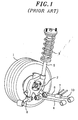
- Fig. 1 shows a suspension system employing a conventional toe angle adjustment mechanism for a rear wheel 1.
- a steering knuckle 2 which is pivotally connected with a first control arm 4, a second control arm 6, and a trailing arm 8.
- a first control arm 4 Arranged generally longitudinal to the vehicle is the trailing arm 8 and traverse to the longitudinal centerline thereof are the first control arm 4 and the second control arm 6.
- the second control arm 6, used for adjusting the steer angle of the rear wheel 1, is connected with a hydraulic linear actuator 7 having a fixing rod 10, which is pivotally connected with a rear cross member (not shown) of a vehicle body (not shown).
- the suspension system further includes a shock absorber 5 and a spring 3 assembled together to vertically support the steering knuckle 2.
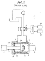
- Fig. 2 illustrates the hydraulic linear actuator 7, which includes a cylinder 11, a cap 12, a piston rod 13, a piston 14, and the fixing rod 10.
- the cylinder 11 has an open end hermetically covered by the cap 12 and a closed end integrally formed with the fixing rod 10.
- One end of the piston rod 13 hermetically passes through the cap 12 and coupled with the piston 14 disposed inside the cylinder 11, while the other end thereof is connected with the second control arm 6.
- the piston 14 partitions an inner space of the cylinder 11 into a first chamber 17 and a second chamber 18.
- Respectively disposed near the closed end and the sealed end of the cylinder 11 are a first port 15 and a second port 16. Hydraulic pressure is selectively applied to the piston 14 via the first and the second port 15 and 16. The piston 14 while being in equilibrium is sustained at the center of the cylinder 11 by a first and a second elastic member 19 and 20, which are disposed at the first chamber 17 and the second chamber 18, respectively.
- Hydraulic pressure applied via the first and the second port 15 and 16 is adjusted by using a hydraulic valve 21, which is electrically controlled by an electronic control unit (ECU).
- ECU electronice control unit
- the ECU controls the operation of the hydraulic valve 21. That is to say, the speed sensor 22 and the steering angle sensor 23 provide feedback information of the vehicle's driving condition to the ECU, which in turn controls the hydraulic valve 21 such that the hydraulic linear actuator 7 can actively adjust the toe angle of the rear wheel 1.
- the above-explained conventional toe angle adjustment mechanism employing the hydraulic linear actuator can be problematic in that the hydraulic units, i.e., the hydraulic linear actuator, occupy relatively large space and yield slow response time. Further, such a hydraulic control system can be fairly complex, involving relatively large number of complicated parts, and, therefore, limiting a production yield.
- a primary object of the present invention to provide a toe angle adjustment mechanism employing an electrical linear actuator that can reduce the response time as well as the occupation of space.
- a toe angle adjustment mechanism for a vehicle having a rear cross member, a pair of rear wheels, and a pair of steering knuckles, the mechanism including: an electrical linear actuator fixedly connected to the rear cross member; a control lever pivotally connected with one of the steering knuckles, each of the knuckles being rotationally coupled with a corresponding rear wheel; and an interconnection arm, rotationally attached to the rear cross member, for interconnecting the control lever and the electrical linear actuator, wherein the electrical linear actuator selectively projects or retracts the interconnection arm, which in turn is rotated about a rotary axis thereof so as to correspondingly retract or project the control lever for the purpose of an active adjustment of a toe angle of the rear wheels.
- the electrical linear actuator preferably includes a housing; an electrical motor attached to an end portion of the housing; a lead screw disposed inside the housing and rotated by the motor; and a nut rod operatively mounted on the lead screw for linear movement therealong in response to a rotation of the lead screw by the electrical motor.
- FIG. 3 to 9 a toe angle adjustment mechanism 100 employing an electrical linear actuator in accordance with a preferred embodiment of the present invention will be described in detail.
- Like numerals represent like parts in the drawings.
- the toe angle adjustment mechanism 100 of a suspension system for a vehicle includes a pair of rear wheels 30, a rear cross member 31, a pair of steering knuckles 32, a pair of control arms 33, a pair of electrical linear actuators 36, and a pair of linkages 37.
- Each of the rear wheels 30 is rotationally coupled with a corresponding steering knuckle 32, which is pivotally connected with the control arm 33 and a trailing arm (not shown).
- the trailing arm supports the steering knuckle 32 that is longitudinal to the vehicle and the control arm 33, traverse to the longitudinal centerline thereof.
- the suspension system further includes a spring 34 and a shock absorber 35 assembled together to vertically support the vehicle against each steering knuckle 32, whereby a vertical vibration of the vehicle is dampened.
- the linkage 37 serving to interconnect the steering knuckle 32 and the electrical linear actuator 36, has a control lever 38 and an interconnection arm 39 pivotally connected together.
- the steering knuckle 32 and the electrical linear actuator 36 are pivotally connected with the control lever 38 and the interconnection arm 39, respectively, wherein a middle point of the interconnection arm 39 is pivotally mounted on a low front portion of the rear cross member 31.
- the electrical linear actuator 36 selectively projects or retracts the interconnection arm 39, which in turn is rotated about a rotary axis thereof, so that the control lever 38 is correspondingly retracted or projected for the purpose of an active adjustment of the toe angle of the rear wheels 30.
- the electrical linear actuator 36 including a direct current (DC) motor 40, a nut rod 41, a lead screw 42, a couple of limit switches 43, a rotation detector 44, and a housing 45.
- the DC motor 40 is mounted on an end of the housing 45 and a drive shaft 51 thereof is connected with the lead screw 42 inside the housing 45.
- the couple of limit switches 43 with a predetermined interval therebetween are positioned above the lead screw 42.
- the rotation detector 44 has a disk 49 and a position sensor 48, which in the preferred embodiment is in the form of a photo-interrupter well known to those skilled in the art.
- the electrical linear actuator 36 is assembled on a bracket 60, wherein the bracket 60 serves to mount the electrical linear actuator 36 on the rear cross member 31 of Fig. 3.
- Each of the nut rod 41 and the lead screw 42 preferably has an Acme threaded profile, e.g., a square thread or a trapezoidal thread.
- the nut rod 41 is operatively mounted on the lead screw 42 for linear movement therealong in response to a rotation of the lead screw 42 by the DC motor 40. If a pitch of the lead screw 42 is about 3 mm, the nut rod 41 correspondingly moves about 3 mm per each rotation of the lead screw 42.
- the couple of limit switches 43 i.e., a first and a second limit switch 43a and 43b, serve to preset a stroke of the electrical linear actuator 36 by detecting a first protrusion 41a of the nut rod 41, so that an optimum operation thereof can be assured.
- the first protrusion 41a is positioned on an end portion of the nut rod 41.
- Each of the limit switches 43 is a photo-sensor or preferably a gap sensor and can be used to set a reference position of the nut rod 41 or compensate errors of the rotation detector 44.
- the electrical linear actuator 36 may be operated by applying a direct-current voltage ranging from about 10 to about 16 V. With a predetermined input voltage of about 13.5 V applied thereto, it is preferred that the electrical linear actuator 36 can be operated at a speed of about 105 mm/s with a load of about 20 Kgf or at about 65 mm/s with a load about 60 Kgf, wherein the load acts on the nut rod 41 along a longitudinal axis thereof. On the other hand, the electrical linear actuator 36 is preferably capable of withstanding an external axial force of about 260 Kgf acting on the nut rod 41. These specifications of the electrical linear actuator 36 are determined by the type of the vehicle employing the toe angle adjustment mechanism 100.
- the electrical linear actuator 36 further includes a bearing 46 fixed in the housing 45 by a bearing stopper 47.
- One end of the lead screw 42 is of a non-threaded shape to be forcibly inserted into an inner part of the bearing 46, which makes the rotation of the lead screw 42 smooth.
- the inner part of the bearing 46 rotates together with the lead screw 42, while an outer part thereof is fixed to the housing 45.
- a rod stopper 59 is installed near the bearing 46 inside the housing 45 to mechanically prevent the nut rod 41 from traveling beyond the second limit switch 43b.
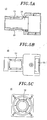
- Figs. 5A to 5C show various views of the housing 45. Referring to Figs. 4 and 5A to 5C, the configuration of the electrical linear actuator 36 will be explained in more detail.
- the housing 45 has therein a hollow portion 58 extending along a longitudinal center axis of the housing 45.
- the lead screw 42 assembled with the nut rod 41 and the bearing 46 is positioned in the hollow portion 58 and the DC motor 40 is mounted on the end of the housing 45.
- the non-threaded end portion of the lead screw 42 is forcibly inserted into the bearing 46 and is coupled with the drive shaft 51 of the DC motor 40 via a coupling element 52.
- first opening portion 53 and a second opening portion 54 Formed through an upper side of the housing 45 are a first opening portion 53 and a second opening portion 54, and formed through a lower side thereof is a third opening portion 63.
- the first opening portion 53 and the second opening portion 54 are positioned at an end region and a middle region of the upper side, respectively, and the third opening portion 63 is positioned at a middle region of the lower side to oppositely face the second opening portion 54.
- the first opening portion 53 is used to install the position sensor 48 against the disk 49.
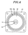
- Fig. 6 illustrates a front view of the disk 49 coupled with the drive shaft 51 of the DC motor 40 at a center hole 50 thereof.
- the disk 49 has a multiplicity of alternating teeth 49a and slits 49b equally spaced around a circumference thereof.
- the position sensor 48 includes a light source (not shown) and a photodetector (not shown) disposed near the circumference of the disk 49 where the teeth 49a and the slits 49b are provided. Therefore, while the DC motor 40 is rotating, the position sensor 48 continuously detects each interruption of light and correspondingly outputs a pulse signal such that rotating angle of the drive shaft 51, i.e., the lead screw 42 of Fig. 4, can be obtained.
- the output of the position sensor 48 serves to monitor the amount of rotation of the lead screw 42 to control the toe angle.
- Fig. 7 shows an exemplary graph obtained from a first and a second pulse signal respectively generated from a first and a second position sensor, which are preferably installed such that the first and the second pulse signal are out of phase by a quarter-cycle.
- the second opening portion 54 is used to install the first limit switch 43a and the second limit switch 43b that respectively set a first end point and a second end point of a stroke of the nut rod 41. Further, the third opening portion 63 is used to install a guide 55, which serves to prevent rotation of the nut rod 41 so as to secure linear movement thereof.
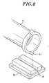
- Fig. 8 shows an assembly configuration of the guide 55 and the nut rod 41.
- the guide 55 has a groove 56 formed along a centerline thereof and the nut rod 41 has a second protrusion 57 positioned at an outer circumference thereof, wherein the second protrusion 57 can smoothly slide along the groove 56.
- the guide 55 and the second protrusion 57 serve to prevent any rotation of the nut rod 41 while the lead screw 42 of Fig. 4 is rotating, so that the nut rod 41 can provide an accurate linear motion between the first end point and the second end point.
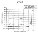
- Fig. 9 shows a graph of signals outputted from the first and the second limit switch 43a and 43b of Fig. 4, wherein a first and a second signal are respectively measured from the first and the second limit switch 43a and 43b while the nut rod 41 of Fig. 4 is moving from the first end point to the second end point.
Abstract
Description
- The present invention relates to an active toe angle adjustment mechanism for a vehicle; and, more particularly, to an active toe angle adjustment mechanism employing an electrical linear actuator for actively adjusting a toe angle of rear wheels in a vehicle.
- A vehicle suspension system is to provide a comfortable ride to a vehicle passenger and improve a driving performance of the vehicle. To the purpose, the vehicle should be effectively shielded from the impact of the force generated due to an irregular road surface condition, whereby a vehicle operator keeps the vehicle under control comfortably, maintaining a good grip and getting a good feedback from the vehicle.
- Such a vehicle suspension system has been developed to better passenger's comfort and improve the driving performance by employing an active toe angle adjustment mechanism. A difference between a steer angle of an inside wheel and that of an outside wheel defines a toe angle. The active toe angle adjustment mechanism controls the toe angle therebetween. Such an active toe angle adjustment mechanism is recently adopted for rear wheels as well as front wheels of a vehicle. Fig. 1 shows a suspension system employing a conventional toe angle adjustment mechanism for a
rear wheel 1. - Rotationally coupled to the
rear wheel 1 is asteering knuckle 2, which is pivotally connected with afirst control arm 4, asecond control arm 6, and atrailing arm 8. Arranged generally longitudinal to the vehicle is thetrailing arm 8 and traverse to the longitudinal centerline thereof are thefirst control arm 4 and thesecond control arm 6. Thesecond control arm 6, used for adjusting the steer angle of therear wheel 1, is connected with a hydrauliclinear actuator 7 having afixing rod 10, which is pivotally connected with a rear cross member (not shown) of a vehicle body (not shown). - The suspension system further includes a shock absorber 5 and a spring 3 assembled together to vertically support the
steering knuckle 2. The shock absorber 5, mounted between thesteering knuckle 2 and the vehicle body, serves to dampen vertical vibration of the vehicle body, together with the spring 3. - Fig. 2 illustrates the hydraulic
linear actuator 7, which includes acylinder 11, acap 12, apiston rod 13, apiston 14, and thefixing rod 10. Thecylinder 11 has an open end hermetically covered by thecap 12 and a closed end integrally formed with thefixing rod 10. One end of thepiston rod 13 hermetically passes through thecap 12 and coupled with thepiston 14 disposed inside thecylinder 11, while the other end thereof is connected with thesecond control arm 6. Thepiston 14 partitions an inner space of thecylinder 11 into afirst chamber 17 and asecond chamber 18. - Respectively disposed near the closed end and the sealed end of the
cylinder 11 are afirst port 15 and asecond port 16. Hydraulic pressure is selectively applied to thepiston 14 via the first and thesecond port piston 14 while being in equilibrium is sustained at the center of thecylinder 11 by a first and a secondelastic member first chamber 17 and thesecond chamber 18, respectively. - Hydraulic pressure applied via the first and the
second port hydraulic valve 21, which is electrically controlled by an electronic control unit (ECU). Based on a signal from asteering angle sensor 23 and/or avehicle speed sensor 22, e.g., a speedometer, the ECU controls the operation of thehydraulic valve 21. That is to say, thespeed sensor 22 and thesteering angle sensor 23 provide feedback information of the vehicle's driving condition to the ECU, which in turn controls thehydraulic valve 21 such that the hydrauliclinear actuator 7 can actively adjust the toe angle of therear wheel 1. - The above-explained conventional toe angle adjustment mechanism employing the hydraulic linear actuator can be problematic in that the hydraulic units, i.e., the hydraulic linear actuator, occupy relatively large space and yield slow response time. Further, such a hydraulic control system can be fairly complex, involving relatively large number of complicated parts, and, therefore, limiting a production yield.
- It is, therefore, a primary object of the present invention to provide a toe angle adjustment mechanism employing an electrical linear actuator that can reduce the response time as well as the occupation of space.
- In accordance with a preferred embodiment of the present invention, there is provided a toe angle adjustment mechanism for a vehicle having a rear cross member, a pair of rear wheels, and a pair of steering knuckles, the mechanism including: an electrical linear actuator fixedly connected to the rear cross member; a control lever pivotally connected with one of the steering knuckles, each of the knuckles being rotationally coupled with a corresponding rear wheel; and an interconnection arm, rotationally attached to the rear cross member, for interconnecting the control lever and the electrical linear actuator, wherein the electrical linear actuator selectively projects or retracts the interconnection arm, which in turn is rotated about a rotary axis thereof so as to correspondingly retract or project the control lever for the purpose of an active adjustment of a toe angle of the rear wheels.
- The electrical linear actuator preferably includes a housing; an electrical motor attached to an end portion of the housing; a lead screw disposed inside the housing and rotated by the motor; and a nut rod operatively mounted on the lead screw for linear movement therealong in response to a rotation of the lead screw by the electrical motor.
- The above and other objects and features of the present invention will become apparent from the following description of a preferred embodiment given in conjunction with the accompanying drawings, in which:
- Fig. 1 presents a perspective view of a conventional toe angle adjustment mechanism employing a hydraulic linear actuator;
- Fig. 2 provides a sectional view of the hydraulic linear actuator shown in Fig. 1 and a control system therefor;
- Fig. 3 represents a front view of a toe angle adjustment mechanism in accordance with a preferred embodiment of the present invention;
- Fig. 4 is a partial cross-sectional view of an electrical linear actuator of the toe angle adjustment mechanism in accordance with the preferred embodiment of the present invention;
- Fig. 5A shows a cross-sectional front view of a housing of the electrical linear actuator shown in Fig. 4;
- Fig. 5B describes a plan view of the housing shown in Fig. 4;
- Fig. 5C illustrates a side view of the housing shown in Fig. 4;
- Fig. 6 sets forth a rotation detector of the toe angle adjustment mechanism in accordance with the preferred embodiment of the present invention;
- Fig. 7 is a graph showing exemplary output signals detected from the rotation detector of Fig. 6;
- Fig. 8 depicts a perspective view of a nut rod and a guide of the electrical linear actuator in accordance with the preferred embodiment of the present invention; and
- Fig. 9 is a graph illustrating exemplary output signals detected from a pair of limit switches.
-
- Referring now to Figs. 3 to 9, a toe
angle adjustment mechanism 100 employing an electrical linear actuator in accordance with a preferred embodiment of the present invention will be described in detail. Like numerals represent like parts in the drawings. - In Fig. 3, the toe
angle adjustment mechanism 100 of a suspension system for a vehicle includes a pair ofrear wheels 30, arear cross member 31, a pair ofsteering knuckles 32, a pair ofcontrol arms 33, a pair of electricallinear actuators 36, and a pair oflinkages 37. Each of therear wheels 30 is rotationally coupled with acorresponding steering knuckle 32, which is pivotally connected with thecontrol arm 33 and a trailing arm (not shown). The trailing arm supports thesteering knuckle 32 that is longitudinal to the vehicle and thecontrol arm 33, traverse to the longitudinal centerline thereof. The suspension system further includes aspring 34 and a shock absorber 35 assembled together to vertically support the vehicle against eachsteering knuckle 32, whereby a vertical vibration of the vehicle is dampened. - The
linkage 37, serving to interconnect thesteering knuckle 32 and the electricallinear actuator 36, has acontrol lever 38 and aninterconnection arm 39 pivotally connected together. Thesteering knuckle 32 and the electricallinear actuator 36 are pivotally connected with thecontrol lever 38 and theinterconnection arm 39, respectively, wherein a middle point of theinterconnection arm 39 is pivotally mounted on a low front portion of therear cross member 31. The electricallinear actuator 36 selectively projects or retracts theinterconnection arm 39, which in turn is rotated about a rotary axis thereof, so that thecontrol lever 38 is correspondingly retracted or projected for the purpose of an active adjustment of the toe angle of therear wheels 30. - Referring to Fig. 4, there is illustrated the electrical
linear actuator 36 including a direct current (DC)motor 40, anut rod 41, alead screw 42, a couple oflimit switches 43, arotation detector 44, and ahousing 45. TheDC motor 40 is mounted on an end of thehousing 45 and adrive shaft 51 thereof is connected with thelead screw 42 inside thehousing 45. The couple oflimit switches 43 with a predetermined interval therebetween are positioned above thelead screw 42. Therotation detector 44 has adisk 49 and aposition sensor 48, which in the preferred embodiment is in the form of a photo-interrupter well known to those skilled in the art. Further, the electricallinear actuator 36 is assembled on abracket 60, wherein thebracket 60 serves to mount the electricallinear actuator 36 on therear cross member 31 of Fig. 3. - Each of the
nut rod 41 and thelead screw 42 preferably has an Acme threaded profile, e.g., a square thread or a trapezoidal thread. Thenut rod 41 is operatively mounted on thelead screw 42 for linear movement therealong in response to a rotation of thelead screw 42 by theDC motor 40. If a pitch of thelead screw 42 is about 3 mm, thenut rod 41 correspondingly moves about 3 mm per each rotation of thelead screw 42. - The couple of
limit switches 43, i.e., a first and asecond limit switch linear actuator 36 by detecting afirst protrusion 41a of thenut rod 41, so that an optimum operation thereof can be assured. Thefirst protrusion 41a is positioned on an end portion of thenut rod 41. Each of thelimit switches 43 is a photo-sensor or preferably a gap sensor and can be used to set a reference position of thenut rod 41 or compensate errors of therotation detector 44. - The electrical
linear actuator 36 may be operated by applying a direct-current voltage ranging from about 10 to about 16 V. With a predetermined input voltage of about 13.5 V applied thereto, it is preferred that the electricallinear actuator 36 can be operated at a speed of about 105 mm/s with a load of about 20 Kgf or at about 65 mm/s with a load about 60 Kgf, wherein the load acts on thenut rod 41 along a longitudinal axis thereof. On the other hand, the electricallinear actuator 36 is preferably capable of withstanding an external axial force of about 260 Kgf acting on thenut rod 41. These specifications of the electricallinear actuator 36 are determined by the type of the vehicle employing the toeangle adjustment mechanism 100. - The electrical
linear actuator 36 further includes abearing 46 fixed in thehousing 45 by a bearingstopper 47. One end of thelead screw 42 is of a non-threaded shape to be forcibly inserted into an inner part of thebearing 46, which makes the rotation of thelead screw 42 smooth. The inner part of thebearing 46 rotates together with thelead screw 42, while an outer part thereof is fixed to thehousing 45. Furthermore, arod stopper 59 is installed near the bearing 46 inside thehousing 45 to mechanically prevent thenut rod 41 from traveling beyond thesecond limit switch 43b. - Figs. 5A to 5C show various views of the
housing 45. Referring to Figs. 4 and 5A to 5C, the configuration of the electricallinear actuator 36 will be explained in more detail. - The
housing 45 has therein ahollow portion 58 extending along a longitudinal center axis of thehousing 45. Thelead screw 42 assembled with thenut rod 41 and thebearing 46 is positioned in thehollow portion 58 and theDC motor 40 is mounted on the end of thehousing 45. The non-threaded end portion of thelead screw 42 is forcibly inserted into thebearing 46 and is coupled with thedrive shaft 51 of theDC motor 40 via acoupling element 52. - Formed through an upper side of the
housing 45 are afirst opening portion 53 and asecond opening portion 54, and formed through a lower side thereof is athird opening portion 63. Thefirst opening portion 53 and thesecond opening portion 54 are positioned at an end region and a middle region of the upper side, respectively, and thethird opening portion 63 is positioned at a middle region of the lower side to oppositely face thesecond opening portion 54. - The
first opening portion 53 is used to install theposition sensor 48 against thedisk 49. Fig. 6 illustrates a front view of thedisk 49 coupled with thedrive shaft 51 of theDC motor 40 at acenter hole 50 thereof. Thedisk 49 has a multiplicity of alternatingteeth 49a and slits 49b equally spaced around a circumference thereof. Theposition sensor 48 includes a light source (not shown) and a photodetector (not shown) disposed near the circumference of thedisk 49 where theteeth 49a and theslits 49b are provided. Therefore, while theDC motor 40 is rotating, theposition sensor 48 continuously detects each interruption of light and correspondingly outputs a pulse signal such that rotating angle of thedrive shaft 51, i.e., thelead screw 42 of Fig. 4, can be obtained. The output of theposition sensor 48 serves to monitor the amount of rotation of thelead screw 42 to control the toe angle. - Employing two position sensors can improve a resolving power of the
rotation detector 44. Fig. 7 shows an exemplary graph obtained from a first and a second pulse signal respectively generated from a first and a second position sensor, which are preferably installed such that the first and the second pulse signal are out of phase by a quarter-cycle. - Under the above-explained condition, uniformly distributed 32 slits at one revolution of the disk can provide a resolving power of about 2.8125° [=360°/(32*2*2)] for the DC motor. With this resolving power, a controllable unit displacement of the
nut rod 41 can be set to about 0.0234 mm (= 3 mm*2.8125°/360°) when thelead screw 42 has a pitch of about 3 mm. - Returning to Figs. 4 and 5A to 5C, the
second opening portion 54 is used to install thefirst limit switch 43a and thesecond limit switch 43b that respectively set a first end point and a second end point of a stroke of thenut rod 41. Further, thethird opening portion 63 is used to install aguide 55, which serves to prevent rotation of thenut rod 41 so as to secure linear movement thereof. - Fig. 8 shows an assembly configuration of the
guide 55 and thenut rod 41. Theguide 55 has agroove 56 formed along a centerline thereof and thenut rod 41 has asecond protrusion 57 positioned at an outer circumference thereof, wherein thesecond protrusion 57 can smoothly slide along thegroove 56. Theguide 55 and thesecond protrusion 57 serve to prevent any rotation of thenut rod 41 while thelead screw 42 of Fig. 4 is rotating, so that thenut rod 41 can provide an accurate linear motion between the first end point and the second end point. - Fig. 9 shows a graph of signals outputted from the first and the
second limit switch second limit switch nut rod 41 of Fig. 4 is moving from the first end point to the second end point. - When the
first protrusion 41a of thenut rod 41 is positioned just below thefirst limit switch 43a or thesecond limit switch 43b, an "ON" state of the corresponding signal, i.e., the first or the second signal is provided. On the contrary, an "OFF" state thereof is provided when thefirst protrusion 41a of thenut rod 41 is positioned far from thefirst limit switch 43a or thesecond limit switch 43b. If the first and the second signal simultaneously show the "ON" state, it indicates, e.g., a failure of the first and/or thesecond limit switch - While the invention has been shown and described with respect to the preferred embodiment, it will be understood to those skilled in the art that various changes and modifications may be made without departing from the scope of the invention as defined in the following claims.
Claims (13)
- A toe angle adjustment mechanism for a vehicle having a rear cross member, a pair of rear wheels, and a pair of steering knuckles, the mechanism comprising:wherein the electrical linear actuator selectively projects or retracts the interconnection arm, which in turn is rotated about a rotary axis thereof so as to correspondingly retract or project the control lever for the purpose of an active adjustment of a toe angle of the rear wheels.an electrical linear actuator fixedly connected to the rear cross member;a control lever pivotally connected with one of the steering knuckles, each of the knuckles being rotationally coupled with a corresponding rear wheel; andan interconnection arm, rotationally attached to the rear cross member, for interconnecting the control lever and the electrical linear actuator,
- The mechanism of claim 1, wherein the electrical linear actuator includes:a housing;an electrical motor attached to an end portion of the housing;a lead screw disposed inside the housing and rotated by the motor; anda nut rod operatively mounted on the lead screw for linear movement therealong in response to a rotation of the lead screw by the electrical motor.
- The mechanism of claim 2, wherein the electrical linear actuator further includes a guide, attached to a lower portion of the housing, and a protrusion positioned at the nut rod, the guide having a groove along which the protrusion slides.
- The mechanism of claim 2, wherein the electrical linear actuator further includes a rotation detector for obtaining an angle of rotation of the lead screw.
- The mechanism of claim 4, wherein the rotation detector has a disk and at least one position sensor.
- The mechanism of claim 2, wherein the electrical linear actuator further includes a pair of limit switches for electronically defining a stroke thereof.
- The mechanism of claim 2, wherein the lead screw has an Acme threaded profile.
- The mechanism of claim 2, wherein the lead screw has a square thread formation.
- The mechanism of claim 2, wherein the lead screw has a trapezoidal thread formation.
- The mechanism of claim 2, wherein the electrical linear actuator further includes a rod stopper, disposed inside the housing, for mechanically preventing an adverse overstroke of the electrical linear actuator.
- The mechanism of claim 2, wherein the nut rod is pivotally connected with an end portion of the interconnection arm.
- The mechanism of claim 2, wherein the electrical motor is a direct current (DC) motor.
- A toe angle adjustment apparatus for a vehicle having a rear cross member, a pair of rear wheels, and a pair of steering knuckles, the apparatus comprising:wherein the electrical linear actuator selectively projects or retracts the interconnection arm, which in turn is rotated about a rotary axis thereof so as to correspondingly retract or project the control lever for the purpose of an active adjustment of a toe angle of the rear wheels.an electrical linear actuator fixedly connected to the rear cross member, the electrical linear actuator includinga) a housing,b) an electrical motor attached to an end portion of the housing,c) a lead screw disposed inside the housing and rotated by the electrical motor, andd) a nut rod operatively mounted on the lead screw for linear movement therealong in response to rotation of the lead screw by the motor;a control lever pivotally connected with one of the steering knuckles, each of the knuckles being rotationally coupled with a corresponding rear wheel; andan interconnection arm, rotationally attached to the rear cross member, for interconnecting the control lever and the electrical linear actuator,
Applications Claiming Priority (6)
| Application Number | Priority Date | Filing Date | Title |
|---|---|---|---|
| KR10-2002-0025194A KR100511738B1 (en) | 2002-05-08 | 2002-05-08 | Rear wheel toe angle control systems of the vehicles |
| KR2002025190 | 2002-05-08 | ||
| KR10-2002-0025190A KR100511737B1 (en) | 2002-05-08 | 2002-05-08 | Rear wheel toe angle control systems of the vehicles |
| KR2002025194 | 2002-05-08 | ||
| KR2002025193 | 2002-05-08 | ||
| KR10-2002-0025193A KR100511740B1 (en) | 2002-05-08 | 2002-05-08 | Rear wheel toe angle control systems of the vehicles |
Publications (3)
| Publication Number | Publication Date |
|---|---|
| EP1361086A2 true EP1361086A2 (en) | 2003-11-12 |
| EP1361086A3 EP1361086A3 (en) | 2005-03-09 |
| EP1361086B1 EP1361086B1 (en) | 2010-08-25 |
Family
ID=29255124
Family Applications (1)
| Application Number | Title | Priority Date | Filing Date |
|---|---|---|---|
| EP03004028A Expired - Lifetime EP1361086B1 (en) | 2002-05-08 | 2003-02-24 | Active toe angle adjustment mechanism |
Country Status (5)
| Country | Link |
|---|---|
| US (1) | US6962356B2 (en) |
| EP (1) | EP1361086B1 (en) |
| JP (1) | JP2003320956A (en) |
| CN (1) | CN1272193C (en) |
| DE (1) | DE60333887D1 (en) |
Cited By (2)
| Publication number | Priority date | Publication date | Assignee | Title |
|---|---|---|---|---|
| EP1655155A1 (en) * | 2004-11-08 | 2006-05-10 | Ford Global Technologies, LLC, A subsidary of Ford Motor Company | Vehicle suspension with an artifical muscle |
| EP1754649A1 (en) * | 2005-08-11 | 2007-02-21 | Schaeffler KG | Device for modifying wheel camber or toe-in |
Families Citing this family (23)
| Publication number | Priority date | Publication date | Assignee | Title |
|---|---|---|---|---|
| US20050051988A1 (en) * | 2003-09-09 | 2005-03-10 | Mircea Gradu | Active toe control system and method for an automotive vehicle |
| KR100599699B1 (en) * | 2004-10-06 | 2006-07-12 | 현대모비스 주식회사 | Control lever for active geometry control suspension |
| JP4305429B2 (en) * | 2005-08-18 | 2009-07-29 | トヨタ自動車株式会社 | In-wheel suspension |
| JP4258506B2 (en) * | 2005-08-30 | 2009-04-30 | トヨタ自動車株式会社 | In-wheel suspension |
| JP4448838B2 (en) * | 2006-08-25 | 2010-04-14 | 本田技研工業株式会社 | Vehicle toe angle variable control device |
| KR100748350B1 (en) * | 2006-09-12 | 2007-08-09 | 주식회사 만도 | Rear wheel toe angle control systems of the vehicles |
| JP2008168743A (en) * | 2007-01-10 | 2008-07-24 | Fuji Heavy Ind Ltd | Vehicle body behavior control device |
| ATE535403T1 (en) * | 2007-05-30 | 2011-12-15 | Honda Motor Co Ltd | VEHICLE CONTROL SYSTEM AND METHOD FOR ERROR ASSESSMENT IN A VEHICLE CONTROL SYSTEM |
| JP5144304B2 (en) * | 2008-02-22 | 2013-02-13 | 本田技研工業株式会社 | Vehicle rear wheel steering device |
| US8306701B2 (en) * | 2008-03-12 | 2012-11-06 | Honda Motor Co., Ltd. | Vehicle toe angle controller |
| JP5090992B2 (en) * | 2008-03-31 | 2012-12-05 | 本田技研工業株式会社 | Telescopic actuator |
| JP5313757B2 (en) * | 2009-04-23 | 2013-10-09 | 本田技研工業株式会社 | Rear wheel toe angle controller |
| JP5432990B2 (en) * | 2009-05-08 | 2014-03-05 | 本田技研工業株式会社 | Rear wheel toe angle control device and electric actuator reference position calibration method in rear wheel toe angle control device |
| CN102049986B (en) * | 2009-10-29 | 2014-10-29 | 汪国胜 | Vehicle hanger |
| CN101788390B (en) * | 2010-01-29 | 2011-06-29 | 浙江大学 | Online measuring and adjusting system for toe-in turn angle of front axle of automobile |
| CN101979268B (en) * | 2010-09-25 | 2012-09-05 | 合肥工业大学 | Automobile steering wheel shimmy control method |
| US8480099B2 (en) * | 2011-06-13 | 2013-07-09 | Scott S. Porta | Apparatus and method for adjusting toe angle in the wheels of a solid axle |
| US9464892B2 (en) * | 2012-01-21 | 2016-10-11 | Harrill Mitchell C | Vehicle integrated wheel alignment monitoring system |
| CN107963122B (en) * | 2017-11-24 | 2020-10-30 | 瑞安市联众汽车零部件有限公司 | Automobile wheel steering mechanism |
| KR102463210B1 (en) * | 2018-06-05 | 2022-11-03 | 현대자동차 주식회사 | Active geometry control suspension |
| CN110075627A (en) * | 2019-04-25 | 2019-08-02 | 武汉正源输送工程有限公司 | A kind of small-sized flat bag filter of dust suppression guide tank systems |
| CN111660744B (en) * | 2020-06-22 | 2021-10-19 | 浙江吉利新能源商用车集团有限公司 | Wheel adjusting method and system |
| CN114354225B (en) * | 2021-12-14 | 2023-08-01 | 桂林航天工业学院 | Automobile rear suspension trailing arm dynamic test equipment |
Citations (3)
| Publication number | Priority date | Publication date | Assignee | Title |
|---|---|---|---|---|
| GB752459A (en) * | 1954-01-14 | 1956-07-11 | Metropolitan Vickers Elelctric | Improved means for the elimination of backlash in screw-thread assemblies |
| FR2561193A1 (en) * | 1984-03-15 | 1985-09-20 | Honda Motor Co Ltd | WHEEL ALIGNMENT CONTROL SYSTEM FOR VEHICLES |
| WO1996037375A1 (en) * | 1995-05-22 | 1996-11-28 | Hyundai Motor Company | A vehicle suspension system for a steerable wheel |
Family Cites Families (5)
| Publication number | Priority date | Publication date | Assignee | Title |
|---|---|---|---|---|
| DD123801A1 (en) * | 1975-07-15 | 1977-01-19 | ||
| JPH0431113A (en) * | 1990-05-28 | 1992-02-03 | Mazda Motor Corp | Suspension device for vehicle |
| DE4020547A1 (en) * | 1990-06-28 | 1992-01-02 | Porsche Ag | DEVICE FOR ACTIVE ADJUSTMENT OF A MOTOR VEHICLE WHEEL |
| US5117700A (en) * | 1991-02-25 | 1992-06-02 | Ross-Hime Designs, Incorporated | Miniature linear actuator |
| JPH10218008A (en) * | 1997-02-12 | 1998-08-18 | Honda Motor Co Ltd | Toe angle control device for vehicle |
-
2003
- 2003-02-24 DE DE60333887T patent/DE60333887D1/en not_active Expired - Lifetime
- 2003-02-24 EP EP03004028A patent/EP1361086B1/en not_active Expired - Lifetime
- 2003-02-24 US US10/373,562 patent/US6962356B2/en not_active Expired - Lifetime
- 2003-03-03 JP JP2003055776A patent/JP2003320956A/en active Pending
- 2003-03-11 CN CNB031201393A patent/CN1272193C/en not_active Expired - Fee Related
Patent Citations (3)
| Publication number | Priority date | Publication date | Assignee | Title |
|---|---|---|---|---|
| GB752459A (en) * | 1954-01-14 | 1956-07-11 | Metropolitan Vickers Elelctric | Improved means for the elimination of backlash in screw-thread assemblies |
| FR2561193A1 (en) * | 1984-03-15 | 1985-09-20 | Honda Motor Co Ltd | WHEEL ALIGNMENT CONTROL SYSTEM FOR VEHICLES |
| WO1996037375A1 (en) * | 1995-05-22 | 1996-11-28 | Hyundai Motor Company | A vehicle suspension system for a steerable wheel |
Cited By (2)
| Publication number | Priority date | Publication date | Assignee | Title |
|---|---|---|---|---|
| EP1655155A1 (en) * | 2004-11-08 | 2006-05-10 | Ford Global Technologies, LLC, A subsidary of Ford Motor Company | Vehicle suspension with an artifical muscle |
| EP1754649A1 (en) * | 2005-08-11 | 2007-02-21 | Schaeffler KG | Device for modifying wheel camber or toe-in |
Also Published As
| Publication number | Publication date |
|---|---|
| US20030209869A1 (en) | 2003-11-13 |
| EP1361086B1 (en) | 2010-08-25 |
| US6962356B2 (en) | 2005-11-08 |
| EP1361086A3 (en) | 2005-03-09 |
| CN1456454A (en) | 2003-11-19 |
| DE60333887D1 (en) | 2010-10-07 |
| CN1272193C (en) | 2006-08-30 |
| JP2003320956A (en) | 2003-11-11 |
Similar Documents
| Publication | Publication Date | Title |
|---|---|---|
| US6962356B2 (en) | Active toe angle adjustment mechanism | |
| US6962355B2 (en) | Active toe angle adjustment mechanism | |
| KR101259206B1 (en) | Steering mechanism, especially for a rear wheel steering mechanism | |
| EP0246116B1 (en) | Camber control system for a motor vehicle | |
| EP1219476A1 (en) | Motor controlled suspension system for adjusting the height of a vehicle body and a damping force | |
| JPH04212673A (en) | Car steering system | |
| JP5738234B2 (en) | Rear wheel toe angle variable vehicle | |
| CN105835945B (en) | A kind of steering mechanism and the wheeled robot including the mechanism | |
| JPH08337106A (en) | Wheel steering device | |
| CN107757704B (en) | Vehicle steering control system and vehicle | |
| JP2009029360A (en) | Vehicular electric damper device | |
| JP4254273B2 (en) | Steering device | |
| KR100511737B1 (en) | Rear wheel toe angle control systems of the vehicles | |
| KR20220068549A (en) | Independent Suspension System | |
| KR100511738B1 (en) | Rear wheel toe angle control systems of the vehicles | |
| KR100511741B1 (en) | Rear wheel toe angle control systems of the vehicles | |
| KR100511742B1 (en) | Rear wheel toe angle control systems of the vehicles | |
| KR100511740B1 (en) | Rear wheel toe angle control systems of the vehicles | |
| KR100646476B1 (en) | A electrical actuator for rear wheel toe angle adjusting in vehicle | |
| KR100535308B1 (en) | Electro-motive actuator for controling rear wheel toe angle of the vehicles | |
| KR100559552B1 (en) | An adjusting apparatus for wheel caster angle in vehicle | |
| KR100599570B1 (en) | Toe angle ajusting apparatus for a torsion beam axle | |
| JPH0435205Y2 (en) | ||
| JP2534940Y2 (en) | Rear wheel steering device | |
| KR101446945B1 (en) | Actuator for active geometry control suspension system |
Legal Events
| Date | Code | Title | Description |
|---|---|---|---|
| PUAI | Public reference made under article 153(3) epc to a published international application that has entered the european phase |
Free format text: ORIGINAL CODE: 0009012 |
|
| AK | Designated contracting states |
Kind code of ref document: A2 Designated state(s): AT BE BG CH CY CZ DE DK EE ES FI FR GB GR HU IE IT LI LU MC NL PT SE SI SK TR |
|
| AX | Request for extension of the european patent |
Extension state: AL LT LV MK RO |
|
| PUAL | Search report despatched |
Free format text: ORIGINAL CODE: 0009013 |
|
| AK | Designated contracting states |
Kind code of ref document: A3 Designated state(s): AT BE BG CH CY CZ DE DK EE ES FI FR GB GR HU IE IT LI LU MC NL PT SE SI SK TR |
|
| AX | Request for extension of the european patent |
Extension state: AL LT LV MK RO |
|
| 17P | Request for examination filed |
Effective date: 20050714 |
|
| AKX | Designation fees paid |
Designated state(s): DE FR GB IT |
|
| 17Q | First examination report despatched |
Effective date: 20071008 |
|
| GRAP | Despatch of communication of intention to grant a patent |
Free format text: ORIGINAL CODE: EPIDOSNIGR1 |
|
| GRAS | Grant fee paid |
Free format text: ORIGINAL CODE: EPIDOSNIGR3 |
|
| RAP1 | Party data changed (applicant data changed or rights of an application transferred) |
Owner name: MANDO CORPORATION |
|
| GRAA | (expected) grant |
Free format text: ORIGINAL CODE: 0009210 |
|
| RAP1 | Party data changed (applicant data changed or rights of an application transferred) |
Owner name: MANDO CORPORATION |
|
| RAP1 | Party data changed (applicant data changed or rights of an application transferred) |
Owner name: MANDO CORPORATION |
|
| AK | Designated contracting states |
Kind code of ref document: B1 Designated state(s): DE FR GB IT |
|
| REG | Reference to a national code |
Ref country code: GB Ref legal event code: FG4D |
|
| REF | Corresponds to: |
Ref document number: 60333887 Country of ref document: DE Date of ref document: 20101007 Kind code of ref document: P |
|
| PG25 | Lapsed in a contracting state [announced via postgrant information from national office to epo] |
Ref country code: IT Free format text: LAPSE BECAUSE OF FAILURE TO SUBMIT A TRANSLATION OF THE DESCRIPTION OR TO PAY THE FEE WITHIN THE PRESCRIBED TIME-LIMIT Effective date: 20100825 |
|
| PLBE | No opposition filed within time limit |
Free format text: ORIGINAL CODE: 0009261 |
|
| STAA | Information on the status of an ep patent application or granted ep patent |
Free format text: STATUS: NO OPPOSITION FILED WITHIN TIME LIMIT |
|
| 26N | No opposition filed |
Effective date: 20110526 |
|
| REG | Reference to a national code |
Ref country code: DE Ref legal event code: R097 Ref document number: 60333887 Country of ref document: DE Effective date: 20110526 |
|
| GBPC | Gb: european patent ceased through non-payment of renewal fee |
Effective date: 20110224 |
|
| REG | Reference to a national code |
Ref country code: FR Ref legal event code: ST Effective date: 20111102 |
|
| PG25 | Lapsed in a contracting state [announced via postgrant information from national office to epo] |
Ref country code: FR Free format text: LAPSE BECAUSE OF NON-PAYMENT OF DUE FEES Effective date: 20110228 |
|
| PG25 | Lapsed in a contracting state [announced via postgrant information from national office to epo] |
Ref country code: GB Free format text: LAPSE BECAUSE OF NON-PAYMENT OF DUE FEES Effective date: 20110224 |
|
| PGFP | Annual fee paid to national office [announced via postgrant information from national office to epo] |
Ref country code: DE Payment date: 20181120 Year of fee payment: 17 |
|
| REG | Reference to a national code |
Ref country code: DE Ref legal event code: R119 Ref document number: 60333887 Country of ref document: DE |
|
| PG25 | Lapsed in a contracting state [announced via postgrant information from national office to epo] |
Ref country code: DE Free format text: LAPSE BECAUSE OF NON-PAYMENT OF DUE FEES Effective date: 20200901 |