EP1360672B1 - Road traffic monitoring system - Google Patents
Road traffic monitoring system Download PDFInfo
- Publication number
- EP1360672B1 EP1360672B1 EP02711047A EP02711047A EP1360672B1 EP 1360672 B1 EP1360672 B1 EP 1360672B1 EP 02711047 A EP02711047 A EP 02711047A EP 02711047 A EP02711047 A EP 02711047A EP 1360672 B1 EP1360672 B1 EP 1360672B1
- Authority
- EP
- European Patent Office
- Prior art keywords
- sensor
- fibre
- optical fibre
- highway
- optical
- Prior art date
- Legal status (The legal status is an assumption and is not a legal conclusion. Google has not performed a legal analysis and makes no representation as to the accuracy of the status listed.)
- Expired - Lifetime
Links
- 238000012544 monitoring process Methods 0.000 title claims description 20
- 239000013307 optical fiber Substances 0.000 claims description 89
- 239000000835 fiber Substances 0.000 claims description 77
- 230000003287 optical effect Effects 0.000 claims description 24
- 238000000034 method Methods 0.000 claims description 19
- 230000035945 sensitivity Effects 0.000 claims description 10
- 238000000926 separation method Methods 0.000 claims description 10
- 229910052751 metal Inorganic materials 0.000 claims description 8
- 239000002184 metal Substances 0.000 claims description 8
- 229910052755 nonmetal Inorganic materials 0.000 claims description 3
- 230000010363 phase shift Effects 0.000 claims description 2
- 239000000463 material Substances 0.000 description 12
- 230000001939 inductive effect Effects 0.000 description 9
- 230000004044 response Effects 0.000 description 7
- 229910000831 Steel Inorganic materials 0.000 description 6
- 238000013461 design Methods 0.000 description 6
- 239000010959 steel Substances 0.000 description 6
- 230000008859 change Effects 0.000 description 4
- 238000005259 measurement Methods 0.000 description 4
- 239000011347 resin Substances 0.000 description 4
- 229920005989 resin Polymers 0.000 description 4
- 238000004458 analytical method Methods 0.000 description 3
- 239000004033 plastic Substances 0.000 description 3
- 229920003023 plastic Polymers 0.000 description 3
- 238000004382 potting Methods 0.000 description 3
- 238000012545 processing Methods 0.000 description 3
- 238000003860 storage Methods 0.000 description 3
- 238000004891 communication Methods 0.000 description 2
- 239000002131 composite material Substances 0.000 description 2
- 238000010276 construction Methods 0.000 description 2
- 238000013480 data collection Methods 0.000 description 2
- 238000010586 diagram Methods 0.000 description 2
- 230000000694 effects Effects 0.000 description 2
- 239000004519 grease Substances 0.000 description 2
- 229920002635 polyurethane Polymers 0.000 description 2
- 239000004814 polyurethane Substances 0.000 description 2
- 230000008569 process Effects 0.000 description 2
- 230000008439 repair process Effects 0.000 description 2
- 238000012360 testing method Methods 0.000 description 2
- 229910000838 Al alloy Inorganic materials 0.000 description 1
- 239000004593 Epoxy Substances 0.000 description 1
- 229910052691 Erbium Inorganic materials 0.000 description 1
- 206010027146 Melanoderma Diseases 0.000 description 1
- 229920005439 Perspex® Polymers 0.000 description 1
- 229910001128 Sn alloy Inorganic materials 0.000 description 1
- 230000001133 acceleration Effects 0.000 description 1
- 239000004411 aluminium Substances 0.000 description 1
- 229910052782 aluminium Inorganic materials 0.000 description 1
- XAGFODPZIPBFFR-UHFFFAOYSA-N aluminium Chemical compound [Al] XAGFODPZIPBFFR-UHFFFAOYSA-N 0.000 description 1
- 238000013459 approach Methods 0.000 description 1
- 230000008901 benefit Effects 0.000 description 1
- 230000001010 compromised effect Effects 0.000 description 1
- 230000001419 dependent effect Effects 0.000 description 1
- 238000009795 derivation Methods 0.000 description 1
- 238000001514 detection method Methods 0.000 description 1
- 239000003822 epoxy resin Substances 0.000 description 1
- UYAHIZSMUZPPFV-UHFFFAOYSA-N erbium Chemical compound [Er] UYAHIZSMUZPPFV-UHFFFAOYSA-N 0.000 description 1
- 238000005562 fading Methods 0.000 description 1
- 229920001903 high density polyethylene Polymers 0.000 description 1
- 239000004700 high-density polyethylene Substances 0.000 description 1
- 238000007689 inspection Methods 0.000 description 1
- 238000005305 interferometry Methods 0.000 description 1
- 238000002955 isolation Methods 0.000 description 1
- 238000004519 manufacturing process Methods 0.000 description 1
- 150000002739 metals Chemical class 0.000 description 1
- 238000012986 modification Methods 0.000 description 1
- 230000004048 modification Effects 0.000 description 1
- 150000002843 nonmetals Chemical class 0.000 description 1
- 238000004806 packaging method and process Methods 0.000 description 1
- 229920000647 polyepoxide Polymers 0.000 description 1
- 239000004926 polymethyl methacrylate Substances 0.000 description 1
- 238000005070 sampling Methods 0.000 description 1
- 239000004065 semiconductor Substances 0.000 description 1
- 239000007779 soft material Substances 0.000 description 1
- 239000011800 void material Substances 0.000 description 1
Images



Classifications
-
- G—PHYSICS
- G08—SIGNALLING
- G08G—TRAFFIC CONTROL SYSTEMS
- G08G1/00—Traffic control systems for road vehicles
- G08G1/01—Detecting movement of traffic to be counted or controlled
-
- E—FIXED CONSTRUCTIONS
- E01—CONSTRUCTION OF ROADS, RAILWAYS, OR BRIDGES
- E01F—ADDITIONAL WORK, SUCH AS EQUIPPING ROADS OR THE CONSTRUCTION OF PLATFORMS, HELICOPTER LANDING STAGES, SIGNS, SNOW FENCES, OR THE LIKE
- E01F11/00—Road engineering aspects of Embedding pads or other sensitive devices in paving or other road surfaces, e.g. traffic detectors, vehicle-operated pressure-sensitive actuators, devices for monitoring atmospheric or road conditions
-
- G—PHYSICS
- G08—SIGNALLING
- G08G—TRAFFIC CONTROL SYSTEMS
- G08G1/00—Traffic control systems for road vehicles
- G08G1/01—Detecting movement of traffic to be counted or controlled
- G08G1/02—Detecting movement of traffic to be counted or controlled using treadles built into the road
Definitions
- inductive sensors Although cheap to produce, inductive sensors are large and as such their placement, particularly in existing roads, causes significant disruption. This has associated costs.
- a major drawback with the use of inductive loops for traffic management is that they are not amenable to multiplexing. Each sensor site requires its own data collection system, power supply and data communication unit. This increases the cost of the complete sensor significantly, which results in the majority of installed inductive loops not being connected, and therefore incapable of collecting data.
- inductive loops can be used to count vehicles and, if deployed in pairs, to determine vehicle speed, they cannot be used to measure dynamic vehicle weight. Vehicle classification is thus not possible.
- a non-Rayleigh backscattering reflectometric system relies upon discrete reflectors between sensors. These are comparatively expensive components, which may add to the cost of the overall system. In contrast, Rayleigh backscattering relies on reflection of light from inhomogeneities in the optical fibre. This removes the need for discrete reflectors, reducing the overall cost of the system. However, the data collected from such a system requires more complex analysis than a reflectometric interrogation system.
- the length of optical fibre connecting adjacent sensor-stations is between 100m and 5000m.
- Ensuring that each lane of the highway has at least one fibre optic sensor means that some traffic information can be collected irrespective of the part of the highway on which traffic is flowing.
- the simplest system for a single lane highway would have two sensors, one for each direction of traffic. Although this would give information regarding vehicle weight, traffic volume and axle count, it could not be used to give a measure of vehicle speed.
- Vehicle speed may however be determined by placing two sensors, separated by a known, short distance, per lane of the highway. It may be desirable to place more than two sensors per lane of the highway, for example three sensors placed in close proximity to each other may be used to give a measure of vehicle acceleration. Such a measurement may be of use at road junctions, roundabouts or traffic lights.
- the sensing fibre and the dummy fibre comprise sections of a single optical fibre. This simplifies the construction of the sensor.
- the sensing fibre and the dummy fibre may be spliced together or joined by any other suitable means.
- the semi-reflective element is either a fibre optic X-coupler with one port mirrored or a Bragg grating.
- the longest dimension of each sensor is substantially equal to the lane width of the highway.
- each sensor is deployed beneath the surface of the highway.
- a thin channel or groove can be cut in the road to accommodate each sensor.
- the groove may then be re-filled and the surface of the road made good again.
- the sensors can simply be incorporated into the structure of the road during construction.
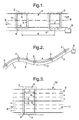
- FIG. 4 A first example of a sensor design is shown in Fig. 4.
- the sensor 12 comprises a sensing fibre 13 and a dummy fibre 14.
- the dummy fibre is shown coiled inside a casing 15.
- a semi-reflective element 16 is coupled to the dummy fibre.
- This arrangement allows a large length of dummy fibre to be contained in a small volume, thereby reducing the overall size of the sensor.
- the dummy fibre may be wound on a reel or former or, if the overall size of the sensor is unimportant, simply left extended.
- a sheath 17 is shown around the sensing fibre 13. This may be separate to, or integral with, the dummy fibre casing 15:
- the sheath 17 serves to protect the sensing fibre from damage. It may for example, comprise a metal or a plastic.
- the cross sectional shape of the sheath is preferably chosen such that it provides the sensor with lateral rigidity.
- the senor In use, the sensor is deployed in such a way that the sensing fibre 13 extends across the width of the highway lane to be interrogated.
- the force exerted by a vehicle passing over the sensing fibre produces a signal which can be detected by the interrogation system.
- the length of the sensing fibre typically around 2 to 4m, means that the sensitivity of the sensor is low. It is thus suitable for detecting the large forces associated with the passage of vehicles.
- the dummy fibre 14 is positioned such that it is not affected by the passage of vehicles. This may be achieved by arranging for the dummy fibre to be at the edge of the highway or between lanes of the highway.
- the packaging of the dummy fibre may be arranged to insulate the fibre from vibrations.
- FIG. 5 A second sensor design is shown in Fig. 5.
- This design of sensor is based around a thin strip 18 which is commonly a metal strip.
- the optical fibre 19 is attached to the strip to form the sensor.
- the optical fibre is wound around two spindles 20 attached to each end of the strip.
- Figs. 5b, 5c and 5d omit the spindles and have the fibre wound around the strip itself.
- the fibre may be wound longitudinally, Fig 5b or helically around the short axis of the strip, Figs. 5c and 5d.
- small indents 21 are made into the edges of the strip 18. These are useful in . locating the optical fibre as it is wound.
- the fibre may be protected by applying a thin overlayer of epoxy or polyurethane (not shown).
- a thin strip as a former provides sensors which are flexible. This enables them to adopt the camber of the highway into which they are deployed and also allows them to be wound onto a drum for ease of storage and deployment.
- modifications to the design of the sensors shown in Fig. 5 may be made without departing from the scope of the present invention.
- Semi-reflective elements have been omitted from Fig. 5 for clarity.
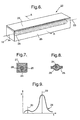
- a further example of a sensor 22 shown in Figs. 6 and 7, comprises an optical fibre 23 wound round a steel bar 24 and placed into a casing 25.
- the optical fibre 23 is a 50m length of double coated, high numerical aperture fibre with an outside diameter of 170 ⁇ m (FibreCore SM1500 - 6.4/80), although other lengths and specifications of optical fibre may equally be used.
- the steel bar 24 is a 3m length of M12 threaded bar and the optical fibre is wound in co-operation with the thread. This makes it simple to wind the optical fibre evenly along the length of the bar.
- a 10mm diameter unthreaded bar can be used in place of the M12 bar, although this makes it more difficult to ensure that the fibre is wound evenly.
- casing may comprise a cylindrical tube with an internal diameter slightly larger that the outer diameter of the bar 24.
- annular void formed between the bar and the casing would be filled with a compliant material.
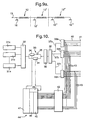
- Fig. 10 shows an example of an interferometric interrogation system.
- the architecture of Fig. 10 is based upon a reflectometric time division multiplexed architecture incorporating some additional wavelength and spatial division multiplexing.
- the light from n distributed feedback (DFB) semiconductor lasers 31 is combined using a dense wavelength division multiplexer (DWDM) 32 before passing through an interferometer 33.
- the interferometer 33 comprises two acousto-optic modulators (AOM) which are also known as Bragg cells 34 and a delay coil 35. Pulses of slightly different frequency drive the Bragg cells 34 so that the light pulses diffracted also have this frequency difference.
- the output from the interferometer is in the form of two separate interrogation pulses.
- each fibre 37 feeds into a 1 x N coupler 39.
- Each coupler 39 splits the input into N fibres 40.
- Each fibre 40 terminates in a sensor, a group of sensors or a number of groups of sensors 41. It is clear that the number of individual sensors which can be interrogated by the architecture of Fig. 8 may be large.
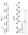
- the pulse train to the sensors consists of a series of pulse pairs, where the pulses are of slightly different frequencies.
- At each end of each sensor is a semi-reflector.
- the pulse separation between the pulses is such that it is equal to the two-way transit time of the light through the fibre between these semi-reflectors.
- the reflection of the second pulse overlaps in time with the reflection from the first pulse from the next semi-reflector along the fibre.
- the pulse train reflected from the sensor array consists of a series of pulses each containing a carrier signal being the difference frequency between the two optical frequencies.
- the detection process at the photodiode results in a series of time-division-multiplexed (TDM) heterodyne pulses, each of which corresponds to a particular sensor in the array.
- TDM time-division-multiplexed
- FIG. 15a shows the response of the sensor as a car is driven over it at three different speeds; 15 mph, 30 mph and 55 mph shown by data curves 58, 59 and 60 respectively.
- Each curve comprises two peaks which correspond to the two axles of the car.
- the distance between the peaks is representative of the axle separation and the axle weight can be derived as a function of the integrated area bounded by each peak and the vehicle speed.
- the vehicle weight can be derived as the speed of the vehicle is known.
- at least two sensors, separated by a known distance are required to measure the speed of a passing vehicle.
Landscapes
- Engineering & Computer Science (AREA)
- Physics & Mathematics (AREA)
- General Physics & Mathematics (AREA)
- General Engineering & Computer Science (AREA)
- Architecture (AREA)
- Civil Engineering (AREA)
- Structural Engineering (AREA)
- Traffic Control Systems (AREA)
- Arrangements For Transmission Of Measured Signals (AREA)
- Geophysics And Detection Of Objects (AREA)
Description
Claims (35)
- A traffic monitoring system, the system comprising at least one sensor station (2) and an interferometric interrogation system (9); wherein the at least one sensor station comprises at least one optical fibre sensor (5) deployed in a highway (10); and wherein the interferometric interrogation system is adapted to respond to an optical phase shift produced in the at least one optical fibre sensor due to a force applied by a vehicle passing the at least one sensor station characterised in that the interferometric interrogation system is a Rayleigh backscatter interferometric interrogation system.
- A system according to claim 1, wherein the interferometric interrogation system comprises a pulsed Rayleigh backscatter interferometric interrogation system.
- A system according to any preceding claim, comprising a plurality of sensor stations, wherein adjacent stations are connected together by a length (3) of optical fibre.
- A system according to claim 3, the length of optical fibre connecting adjacent sensor stations is between 100m and 5000m.
- A system according to any preceding claim, wherein each sensor station comprises a plurality of optical fibre sensors.
- A system according to claim 5, wherein each sensor station comprises at least one optical fibre sensor per lane of the highway.
- A system according to claim 5 or claim 6, wherein each sensor station comprises at least two optical fibre sensors, separated from each other by a known distance, per lane of the highway.
- A system according to claim 7, wherein the known distance is between 0.5 and 5m.
- A system according to any preceding claim, wherein each sensor is deployed so that its longest dimension is substantially in the plane of the highway and substantially perpendicular to the direction of traffic flow on the highway.
- A system according to any preceding claim, wherein the longest dimension of each sensor is substantially equal to the lane width of the highway.
- A system according to any preceding claim, wherein each sensor is deployed beneath the surface of the highway.
- A system according to any preceding claim, wherein the optical fibre sensor comprises a sensing fibre coupled to a dummy fibre; wherein the optical path length of the sensing fibre is such that the sensitivity of the sensor is low; and wherein the optical path length of the dummy fibre is greater than that of the sensing fibre such that the combined optical path length of the sensing fibre and the dummy fibre is sufficient to allow the sensor to be interrogated by an interferrometric interrogation system.
- A system according to claim 12, wherein the optical path length of the dummy fibre is at least 2 times greater than that of the sensing fibre.
- A system according to claim 12 or claim 13, wherein the sensing fibre is substantially straight.
- A system according to any of claims 12 to 14, wherein the sensing fibre and the dummy fibre comprise sections of a single optical fibre.
- A system according to any of claims 12 to 15, wherein the optical fibre sensor further comprises at least one semi-reflective element coupled to the optical fibre.
- A system according to claim 16, wherein the semi-reflective element is located on the dummy fibre of the optical fibre sensor.
- A system according to claim 16 or claim 17, wherein the semi-reflective element is either a fibre optic X-coupler with one port mirrored or a Bragg grating.
- A system according to any of claims 12 to 18, further comprising a casing substantially surrounding at least one of the sensing fibre and the dummy fibre.
- A system according to any of claims 1 to 11, wherein the optical fibre sensor comprises a former and an optical fibre wound on the former; wherein the former is substantially planar; and wherein the sensor is sufficiently flexible such that it is able to substantially adopt the shape of the camber of a highway.
- A system according to claim 20, wherein the former comprises an elongate strip provided with two spindles; wherein the spindles are fixedly attached to the same face of the strip and disposed at a distance from each other, wherein each spindle protrudes substantially perpendicularly from the surface of the strip; and wherein the optical fibre is wound longitudinally between the spindles.
- A system according to claim 20, wherein the former comprises an elongate strip and the optical fibre is wound longitudinally around the long axis of the strip.
- A system according to claim 20, wherein the former comprises an elongate strip and the optical fibre is wound helically around the short axis of the strip.
- A system according to any of claims 21 to 23, wherein the elongate strip comprises a metal strip.
- A system according to any of claims 21 to 23, wherein the elongate strip comprises a non-metal.
- A system according to any of claims 21 to 25, wherein the optical fibre sensor further comprises at least one semi-reflective element coupled to the optical fibre.
- A system according to claim 26, wherein the semi-reflective element is either a fibre optic X-coupler with one port mirrored or a Bragg grating.
- A method for monitoring traffic, the method comprising providing a plurality of sensor stations on a highway; deploying a plurality of optical fibre sensors at each sensor station; interfacing each optical fibre sensor to an interferometric interrogation system, employing time division multiplexing such that the interrogation system is adapted to monitor an output of each optical fibre sensor substantially simultaneously; and using the output of each optical fibre sensor to derive data relating to the traffic passing each sensor station, characterised in that the interferometric interrogation system is a Rayleigh backscatter interferometric interrogation system.
- A method according to claim 28, further employing wavelength division multiplexing such that the number of optical fibre sensors which the interrogation system is adapted to monitor is increased.
- A method according to claim 28 or claim 29, further employing spatial division multiplexing such that the number of optical fibre sensors which the interrogation system is adapted to monitor is increased.
- A method according to any of claims 28 to 30, wherein the data derived relates to vehicle speed.
- A method according to any of claims 28 to 30, wherein the data derived relates to vehicle weight.
- A method according to any of claims 28 to 30, wherein the data derived relates to traffic volume.
- A method according to any of claims 28 to 30, wherein the data derived relates to axle separation.
- A method according to any of claims 28 to 30, wherein the data derived relates to vehicle classification.
Priority Applications (1)
| Application Number | Priority Date | Filing Date | Title |
|---|---|---|---|
| EP04075994A EP1445748B1 (en) | 2001-02-15 | 2002-02-11 | Road traffic monitoring system |
Applications Claiming Priority (3)
| Application Number | Priority Date | Filing Date | Title |
|---|---|---|---|
| GBGB0103665.6A GB0103665D0 (en) | 2001-02-15 | 2001-02-15 | Road traffic monitoring system |
| GB0103665 | 2001-02-15 | ||
| PCT/GB2002/000573 WO2002065425A1 (en) | 2001-02-15 | 2002-02-11 | Road traffic monitoring system |
Related Child Applications (1)
| Application Number | Title | Priority Date | Filing Date |
|---|---|---|---|
| EP04075994A Division EP1445748B1 (en) | 2001-02-15 | 2002-02-11 | Road traffic monitoring system |
Publications (2)
| Publication Number | Publication Date |
|---|---|
| EP1360672A1 EP1360672A1 (en) | 2003-11-12 |
| EP1360672B1 true EP1360672B1 (en) | 2004-09-01 |
Family
ID=9908740
Family Applications (3)
| Application Number | Title | Priority Date | Filing Date |
|---|---|---|---|
| EP04075994A Expired - Lifetime EP1445748B1 (en) | 2001-02-15 | 2002-02-11 | Road traffic monitoring system |
| EP02711047A Expired - Lifetime EP1360672B1 (en) | 2001-02-15 | 2002-02-11 | Road traffic monitoring system |
| EP02711074A Expired - Lifetime EP1360673B1 (en) | 2001-02-15 | 2002-02-12 | Traffic monitoring |
Family Applications Before (1)
| Application Number | Title | Priority Date | Filing Date |
|---|---|---|---|
| EP04075994A Expired - Lifetime EP1445748B1 (en) | 2001-02-15 | 2002-02-11 | Road traffic monitoring system |
Family Applications After (1)
| Application Number | Title | Priority Date | Filing Date |
|---|---|---|---|
| EP02711074A Expired - Lifetime EP1360673B1 (en) | 2001-02-15 | 2002-02-12 | Traffic monitoring |
Country Status (6)
| Country | Link |
|---|---|
| US (2) | US7042369B2 (en) |
| EP (3) | EP1445748B1 (en) |
| JP (2) | JP2004523042A (en) |
| DE (3) | DE60201126T2 (en) |
| GB (1) | GB0103665D0 (en) |
| WO (2) | WO2002065425A1 (en) |
Cited By (1)
| Publication number | Priority date | Publication date | Assignee | Title |
|---|---|---|---|---|
| FR3135324A1 (en) | 2022-05-06 | 2023-11-10 | Osmos Group | Method, system and sensor for monitoring a structure by optical fiber |
Families Citing this family (75)
| Publication number | Priority date | Publication date | Assignee | Title |
|---|---|---|---|---|
| WO2003025524A1 (en) * | 2001-09-19 | 2003-03-27 | Gebert Ruediger Heinz | Weight sensor |
| GB2389947B (en) * | 2002-07-25 | 2004-06-02 | Golden River Traffic Ltd | Automatic validation of sensing devices |
| JP4138523B2 (en) * | 2003-02-18 | 2008-08-27 | いであ株式会社 | Road monitoring system |
| GB2406376A (en) * | 2003-09-24 | 2005-03-30 | Qinetiq Ltd | Surveillance system including serial array of fiber optic point sensors |
| GB0322859D0 (en) | 2003-09-30 | 2003-10-29 | British Telecomm | Communication |
| US7667849B2 (en) | 2003-09-30 | 2010-02-23 | British Telecommunications Public Limited Company | Optical sensor with interferometer for sensing external physical disturbance of optical communications link |
| US7245217B2 (en) * | 2004-03-06 | 2007-07-17 | Fibera, Inc. | Hazard mitigation for railway track intrusions at train station platforms |
| US7268699B2 (en) * | 2004-03-06 | 2007-09-11 | Fibera, Inc. | Highway-rail grade crossing hazard mitigation |
| JP3896465B2 (en) * | 2004-09-17 | 2007-03-22 | 国立大学法人東京工業大学 | Bridge characteristic change detection system |
| GB0421747D0 (en) | 2004-09-30 | 2004-11-03 | British Telecomm | Distributed backscattering |
| EP1794904A1 (en) | 2004-09-30 | 2007-06-13 | British Telecommunications Public Limited Company | Identifying or locating waveguides |
| JP2006144246A (en) * | 2004-11-16 | 2006-06-08 | Save Machine Co Ltd | Road-surface cutting method for forming groove section for embedding loop sensor, and traffic information control system using it |
| GB0427733D0 (en) | 2004-12-17 | 2005-01-19 | British Telecomm | Optical system |
| US7142737B1 (en) * | 2005-01-12 | 2006-11-28 | Network Integrity Systems Inc. | Intrusion detection system for use on single mode optical fiber using a storage register for data |
| US20060186276A1 (en) * | 2005-02-18 | 2006-08-24 | Fibera, Inc. | System for grade crossing accident mitigation |
| GB0504579D0 (en) | 2005-03-04 | 2005-04-13 | British Telecomm | Communications system |
| ATE434774T1 (en) | 2005-03-04 | 2009-07-15 | British Telecomm | ACOUSTOPTICAL MODULATOR ARRANGEMENT |
| EP1708388A1 (en) | 2005-03-31 | 2006-10-04 | British Telecommunications Public Limited Company | Communicating information |
| EP1713301A1 (en) | 2005-04-14 | 2006-10-18 | BRITISH TELECOMMUNICATIONS public limited company | Method and apparatus for communicating sound over an optical link |
| EP1729096A1 (en) | 2005-06-02 | 2006-12-06 | BRITISH TELECOMMUNICATIONS public limited company | Method and apparatus for determining the position of a disturbance in an optical fibre |
| US20070031084A1 (en) * | 2005-06-20 | 2007-02-08 | Fibera, Inc. | Trafic monitoring system |
| GB0521713D0 (en) | 2005-10-25 | 2005-11-30 | Qinetiq Ltd | Traffic sensing and monitoring apparatus |
| KR100797394B1 (en) * | 2005-12-08 | 2008-01-28 | 한국전자통신연구원 | Traffic congestion information providing device and method for road installation |
| WO2007096579A1 (en) | 2006-02-24 | 2007-08-30 | British Telecommunications Public Limited Company | Sensing a disturbance |
| ATE505861T1 (en) | 2006-02-24 | 2011-04-15 | British Telecomm | DETECTING A FAULT |
| EP1826924A1 (en) | 2006-02-24 | 2007-08-29 | BRITISH TELECOMMUNICATIONS public limited company | Sensing a disturbance |
| US8670662B2 (en) | 2006-04-03 | 2014-03-11 | British Telecommunications Public Limited Company | Evaluating the position of an optical fiber disturbance |
| GB2443661B (en) | 2006-11-08 | 2011-08-31 | Polarmetrix Ltd | Detecting a disturbance in the phase of light propogating in an optical waveguide |
| DE102007011232A1 (en) * | 2007-03-06 | 2008-09-11 | Siemens Ag | Method for interrogating a measured value |
| NL2000697C2 (en) * | 2007-06-11 | 2008-12-12 | Konink Bam Groep Nv | Slim object e.g. traffic sensor, mounting method for road, involves heating asphalt at spot of region in which traffic sensor is to be included, and applying force to asphalt to form floor in asphalt |
| FR2922352B1 (en) * | 2007-10-15 | 2009-11-20 | Ecole Superieure D Electroniqu | DEVICE FOR DETECTING THE POSITION OF AN OBJECT IN A ZONE AND SYSTEM FOR DETERMINING THE POSITION OF AN OBJECT IN A ZONE WHICH USES ONE OR MORE OF SUCH DETECTION DEVICES. |
| CN101468651B (en) * | 2007-12-27 | 2011-03-23 | 同方威视技术股份有限公司 | Train information automatic recognition method and system |
| WO2012012903A1 (en) * | 2010-07-30 | 2012-02-02 | Universite Laval | Pavement stress analysis sensor |
| US8866638B2 (en) * | 2011-05-23 | 2014-10-21 | GM Global Technology Operations LLC | Acquisition of travel- and vehicle-related data |
| US9429463B2 (en) | 2013-03-04 | 2016-08-30 | International Road Dynamics, Inc. | System and method for measuring moving vehicle information using electrical time domain reflectometry |
| GB2513399B (en) * | 2013-04-26 | 2017-07-26 | Optasense Holdings Ltd | Traffic Monitoring |
| EP2804166A1 (en) * | 2013-05-13 | 2014-11-19 | PSS Consultancy & Equipment B.V. | Sensor cable and system |
| FR3008789B1 (en) * | 2013-07-22 | 2023-05-12 | Commissariat Energie Atomique | METHOD FOR CHARACTERIZING MECHANICAL PARAMETERS OF A PAVEMENT |
| WO2015069623A1 (en) * | 2013-11-08 | 2015-05-14 | United Technologies Corporation | Fiber grating temperature sensor |
| FR3019291B1 (en) * | 2014-03-31 | 2017-12-01 | Institut Francais Des Sciences Et Technologies Des Transp De L'amenagement Et Des Reseaux | ACQUISITION DEVICE, METHOD FOR MANUFACTURING THE SAME, FORCE MEASURING METHOD |
| CN104318774B (en) * | 2014-11-09 | 2016-05-11 | 应国珍 | Highway mobile monitor facility |
| GB201503855D0 (en) * | 2015-03-06 | 2015-04-22 | Q Free Asa | Vehicle detection |
| CN105208328B (en) * | 2015-09-06 | 2018-07-06 | 浙江省公安厅高速公路交通警察总队宁波支队 | A kind of highway mobile monitoring system |
| CZ307510B6 (en) * | 2015-09-18 | 2018-10-31 | CROSS ZlĂn, a.s. | A device for weight measurement and a measurement method |
| GB201519202D0 (en) * | 2015-10-30 | 2015-12-16 | Optasense Holdings Ltd | Monitoring traffic flow |
| NL2016744B1 (en) * | 2016-05-09 | 2017-11-16 | Fugro Tech Bv | Fiber-optic based traffic and infrastructure monitoring system |
| US20180025317A1 (en) * | 2016-07-21 | 2018-01-25 | At&T Mobility Ii Llc | Facilitating use and management of smart vehicles and smart vehicle infrastructure |
| CN106441530B (en) * | 2016-08-31 | 2017-06-16 | 东南大学 | A kind of bridge dynamic weighing method and dynamic weighing system based on long gauge length optical fibre grating sensing technique |
| CN106448188B (en) * | 2016-10-29 | 2018-11-16 | 浙江大学 | The two-way flow speeds estimation method of road interval based on distributed acoustic sensing data |
| NL2017957B1 (en) * | 2016-12-08 | 2018-06-19 | Fugro Tech Bv | Airport monitoring system |
| JP6846208B2 (en) * | 2017-01-17 | 2021-03-24 | 東日本旅客鉄道株式会社 | Railway control system using optical cable |
| JP6846209B2 (en) * | 2017-01-17 | 2021-03-24 | 東日本旅客鉄道株式会社 | Railroad crossing control system and railway control system using optical cable |
| DE102017210907A1 (en) * | 2017-06-28 | 2019-01-03 | Robert Bosch Gmbh | Floor sensor device for detecting motor vehicles |
| BR102017017613B1 (en) * | 2017-08-16 | 2023-12-26 | Velsis Sistemas E Tecnologia Viaria S/A | DYNAMIC WEIGHING AND VEHICLE SPEED MONITORING SYSTEM ON TRACK |
| NL2020873B1 (en) * | 2018-05-03 | 2019-11-12 | Fugro Tech Bv | Load cell device, sensor system and use of a load cell device. |
| JP7234616B2 (en) * | 2018-12-13 | 2023-03-08 | セイコーエプソン株式会社 | Vehicle detection method |
| US11967229B1 (en) * | 2019-04-19 | 2024-04-23 | Board Of Trustees Of The University Of Alabama, For And On Behalf Of The University Of Alabama In Huntsville | Systems and methods for monitoring vehicular traffic |
| US11468667B2 (en) * | 2019-06-19 | 2022-10-11 | Nec Corporation | Distributed intelligent traffic informatics using fiber sensing |
| EP4006514B1 (en) * | 2019-07-30 | 2024-09-18 | Mitsubishi Electric Corporation | Temperature measuring system and method for manufacturing same |
| US12236776B2 (en) * | 2020-01-27 | 2025-02-25 | Nec Corporation | Traffic monitoring apparatus, system, traffic monitoring method and non-transitory computer readable medium |
| US11562646B2 (en) * | 2020-04-07 | 2023-01-24 | Nec Corporation | Multiple lane real-time traffic monitor and vehicle analysis using distributed fiber sensing |
| US11619541B2 (en) * | 2020-04-14 | 2023-04-04 | Nec Corporation | Vehicle speed, direction, and size measurement using temporal distributed fiber optic sensing |
| WO2022024208A1 (en) * | 2020-07-28 | 2022-02-03 | 日本電気株式会社 | Traffic monitoring device, traffic monitoring system, traffic monitoring method, and program |
| CN112796249A (en) * | 2020-12-30 | 2021-05-14 | 北京科技大学 | A packaged and buried structure and method for distributed optical fiber strain sensor |
| BR102021004560A2 (en) * | 2021-03-10 | 2022-09-20 | Velsis Sistemas E Tecnologia Viaria Ltda | WEIGHING IN MOTION SYSTEM FOR AUTOMOTIVE VEHICLES BASED ON FLEXIBLE SENSORS AND FIBER OPTICS |
| JP7525061B2 (en) * | 2021-04-23 | 2024-07-30 | 日本電気株式会社 | Traffic flow monitoring device, traffic flow monitoring method and program |
| CN113295248B (en) * | 2021-04-28 | 2022-11-29 | 广州铁路职业技术学院(广州铁路机械学校) | A Method of Monitoring Vehicle Overload Based on Distributed Optical Fiber |
| CN113838300A (en) * | 2021-09-26 | 2021-12-24 | 武汉理工大学 | Non-blind area real-time monitoring and alarming system for expressway emergency |
| JPWO2023053184A1 (en) * | 2021-09-28 | 2023-04-06 | ||
| US12106664B2 (en) * | 2021-10-22 | 2024-10-01 | Nec Corporation | Dynamic road traffic noise mapping using distributed fiber optic sensing (DFOS) over telecom network |
| CN115410403B (en) * | 2022-04-19 | 2023-11-10 | 北京见合八方科技发展有限公司 | Road vehicle positioning tracking method and device based on passive perception and readable medium |
| JPWO2024224569A1 (en) * | 2023-04-27 | 2024-10-31 | ||
| WO2026094175A1 (en) * | 2024-10-30 | 2026-05-07 | Ntt株式会社 | Vehicle speed measurement system |
| WO2026094174A1 (en) * | 2024-10-30 | 2026-05-07 | Ntt株式会社 | Vehicle counting system |
| WO2026094176A1 (en) * | 2024-10-30 | 2026-05-07 | Ntt株式会社 | Vehicle type inference system |
Family Cites Families (22)
| Publication number | Priority date | Publication date | Assignee | Title |
|---|---|---|---|---|
| FR2331802A1 (en) * | 1975-11-14 | 1977-06-10 | Thomson Csf | OPTICAL COUPLING DEVICE FOR INTERCONNECTION OF LIGHT GUIDES IN AN OPTICAL TRANSMISSION SYSTEM, AND CORRESPONDING TRANSMISSION SYSTEM |
| US5026141A (en) * | 1981-08-24 | 1991-06-25 | G2 Systems Corporation | Structural monitoring system using fiber optics |
| DE3311524C2 (en) * | 1983-03-30 | 1985-11-14 | Licentia Patent-Verwaltungs-Gmbh, 6000 Frankfurt | Fiber optic sensor for force and pressure measurements as well as for monitoring and protection purposes |
| JPH076862B2 (en) * | 1986-04-30 | 1995-01-30 | 日本電信電話株式会社 | Optical fiber pressure sensor |
| AU2770189A (en) | 1988-01-06 | 1989-07-06 | Unisearch Limited | Use of optical fibre in pressure sensitive transducers |
| JPH0210232A (en) * | 1988-06-29 | 1990-01-16 | Matsushita Electric Ind Co Ltd | Optical fiber sensor |
| JP2521344B2 (en) * | 1989-02-20 | 1996-08-07 | 三菱重工業株式会社 | Tread device |
| US5056884A (en) * | 1990-04-10 | 1991-10-15 | Automatic Toll Systems, Inc. | Fiber optic load sensing device |
| FR2673749B1 (en) | 1991-03-08 | 1995-06-23 | Electronique Controle Mesure | DEVICE FOR DETECTING PASSAGE ON A PAVEMENT, AND ITS METHOD OF LAYING. |
| US5194847A (en) * | 1991-07-29 | 1993-03-16 | Texas A & M University System | Apparatus and method for fiber optic intrusion sensing |
| US5260520A (en) * | 1992-04-02 | 1993-11-09 | Martin Marietta Energy Systems, Inc. | Apparatus for weighing and identifying characteristics of a moving vehicle |
| JP2573837Y2 (en) * | 1992-12-25 | 1998-06-04 | 三菱重工業株式会社 | Vehicle detection device |
| DE4304298A1 (en) * | 1993-02-15 | 1994-08-18 | Atlas Elektronik Gmbh | Method for classifying vehicles passing a given waypoint |
| FR2703451B1 (en) | 1993-04-02 | 1995-05-12 | Alcatel Cable | Interferometric measurement device in polarized light. |
| US5497233A (en) * | 1994-07-27 | 1996-03-05 | Litton Systems, Inc. | Optical waveguide vibration sensor and method |
| JPH0949776A (en) * | 1995-08-09 | 1997-02-18 | Sumitomo Electric Ind Ltd | Optical cable and pressure measurement system |
| JPH102809A (en) * | 1996-06-13 | 1998-01-06 | Ngk Spark Plug Co Ltd | Pressure detector |
| JP3528435B2 (en) * | 1996-06-27 | 2004-05-17 | トヨタ自動車株式会社 | Road object detection device |
| JPH10148586A (en) | 1996-11-19 | 1998-06-02 | Furukawa Electric Co Ltd:The | Embedded structure of optical fiber cable |
| US5913245A (en) * | 1997-07-07 | 1999-06-15 | Grossman; Barry G. | Flexible optical fiber sensor tapes, systems and methods |
| JPH11232586A (en) * | 1998-02-18 | 1999-08-27 | Omron Corp | Wheel spacing calculator |
| US6463187B1 (en) * | 1998-08-24 | 2002-10-08 | Empirical Technologies Corporation | Variable coupler fiberoptic sensor and sensing apparatus using the sensor |
-
2001
- 2001-02-15 GB GBGB0103665.6A patent/GB0103665D0/en not_active Ceased
-
2002
- 2002-02-11 EP EP04075994A patent/EP1445748B1/en not_active Expired - Lifetime
- 2002-02-11 DE DE60201126T patent/DE60201126T2/en not_active Expired - Lifetime
- 2002-02-11 WO PCT/GB2002/000573 patent/WO2002065425A1/en not_active Ceased
- 2002-02-11 US US10/467,075 patent/US7042369B2/en not_active Expired - Lifetime
- 2002-02-11 EP EP02711047A patent/EP1360672B1/en not_active Expired - Lifetime
- 2002-02-11 DE DE60223071T patent/DE60223071T2/en not_active Expired - Lifetime
- 2002-02-11 JP JP2002565273A patent/JP2004523042A/en active Pending
- 2002-02-12 EP EP02711074A patent/EP1360673B1/en not_active Expired - Lifetime
- 2002-02-12 US US10/468,064 patent/US7068186B2/en not_active Expired - Lifetime
- 2002-02-12 JP JP2002565274A patent/JP2004527030A/en active Pending
- 2002-02-12 WO PCT/GB2002/000618 patent/WO2002065426A1/en not_active Ceased
- 2002-02-12 DE DE60200789T patent/DE60200789T2/en not_active Expired - Lifetime
Cited By (1)
| Publication number | Priority date | Publication date | Assignee | Title |
|---|---|---|---|---|
| FR3135324A1 (en) | 2022-05-06 | 2023-11-10 | Osmos Group | Method, system and sensor for monitoring a structure by optical fiber |
Also Published As
| Publication number | Publication date |
|---|---|
| WO2002065426A1 (en) | 2002-08-22 |
| DE60223071D1 (en) | 2007-11-29 |
| US7068186B2 (en) | 2006-06-27 |
| EP1360673B1 (en) | 2004-07-21 |
| US20040080432A1 (en) | 2004-04-29 |
| DE60201126D1 (en) | 2004-10-07 |
| DE60201126T2 (en) | 2005-09-22 |
| DE60223071T2 (en) | 2008-07-24 |
| DE60200789D1 (en) | 2004-08-26 |
| US7042369B2 (en) | 2006-05-09 |
| EP1445748A3 (en) | 2004-09-01 |
| JP2004527030A (en) | 2004-09-02 |
| DE60200789T2 (en) | 2005-07-21 |
| WO2002065425A1 (en) | 2002-08-22 |
| GB0103665D0 (en) | 2001-03-28 |
| EP1360673A1 (en) | 2003-11-12 |
| US20040061628A1 (en) | 2004-04-01 |
| JP2004523042A (en) | 2004-07-29 |
| EP1445748B1 (en) | 2007-10-17 |
| EP1360672A1 (en) | 2003-11-12 |
| EP1445748A2 (en) | 2004-08-11 |
Similar Documents
| Publication | Publication Date | Title |
|---|---|---|
| EP1445748B1 (en) | Road traffic monitoring system | |
| EP1360671B1 (en) | Road traffic monitoring system | |
| US6917308B2 (en) | Surface-mount traffic sensors | |
| CA2106635C (en) | Railway coded track circuit apparatus and method utilizing fiber optic sensing | |
| Mimbela et al. | Summary of vehicle detection and surveillance technologies used in intelligent transportation systems | |
| US10198946B2 (en) | Traffic monitoring | |
| EP2372322B1 (en) | System and method for determining the axle load of a vehicle and a sensor device | |
| CN101397021A (en) | Vehicle running monitoring system based on optical fibre grating | |
| US5913245A (en) | Flexible optical fiber sensor tapes, systems and methods | |
| EP0564054B1 (en) | Traffic detection cable installation | |
| CN108109395A (en) | A kind of vehicle-state detecting system based on fiber grating | |
| WO2001027569A1 (en) | Vehicle weigh-in-motion method and system | |
| WO2023004484A1 (en) | System for weighing moving motor vehicles based on rigid sensors and fibre optics | |
| Kunzler et al. | Fiber grating traffic monitoring systems | |
| JP2001228264A (en) | Road-surface freezing predicting system | |
| EP0770978A1 (en) | Metallic mass detection system | |
| US20200122521A1 (en) | System for assessing the condition of a vehicle, installed near a road infrastructure | |
| Hill et al. | Vehicle weigh-in-motion using multiplexed interferometric sensors | |
| GB2413629A (en) | Combined optical and electrical cable for traffic control and monitoring | |
| RO135230A2 (en) | Sensor for weighing motor vehicles while running and for monitoring urban traffic | |
| Meller et al. | Optical fiber sensors for vehicle detection | |
| CN115331455A (en) | Method and system for road vehicle lane level positioning and vehicle situation monitoring | |
| JPH06265368A (en) | Automatic input system of road distance data | |
| Wierzba | Optical fibre sensors for weigh-in-motion of road vehicles: state-of-the-art and future |
Legal Events
| Date | Code | Title | Description |
|---|---|---|---|
| PUAI | Public reference made under article 153(3) epc to a published international application that has entered the european phase |
Free format text: ORIGINAL CODE: 0009012 |
|
| 17P | Request for examination filed |
Effective date: 20030730 |
|
| AK | Designated contracting states |
Kind code of ref document: A1 Designated state(s): AT BE CH CY DE DK ES FI FR GB GR IE IT LI LU MC NL PT SE TR |
|
| AX | Request for extension of the european patent |
Extension state: AL LT LV MK RO SI |
|
| GRAP | Despatch of communication of intention to grant a patent |
Free format text: ORIGINAL CODE: EPIDOSNIGR1 |
|
| GRAS | Grant fee paid |
Free format text: ORIGINAL CODE: EPIDOSNIGR3 |
|
| GRAA | (expected) grant |
Free format text: ORIGINAL CODE: 0009210 |
|
| AK | Designated contracting states |
Kind code of ref document: B1 Designated state(s): DE FR GB IT |
|
| REG | Reference to a national code |
Ref country code: GB Ref legal event code: FG4D |
|
| REF | Corresponds to: |
Ref document number: 60201126 Country of ref document: DE Date of ref document: 20041007 Kind code of ref document: P |
|
| ET | Fr: translation filed | ||
| PLBE | No opposition filed within time limit |
Free format text: ORIGINAL CODE: 0009261 |
|
| STAA | Information on the status of an ep patent application or granted ep patent |
Free format text: STATUS: NO OPPOSITION FILED WITHIN TIME LIMIT |
|
| 26N | No opposition filed |
Effective date: 20050602 |
|
| REG | Reference to a national code |
Ref country code: DE Ref legal event code: R082 Ref document number: 60201126 Country of ref document: DE Representative=s name: BEETZ & PARTNER PATENT- UND RECHTSANWAELTE, DE |
|
| REG | Reference to a national code |
Ref country code: GB Ref legal event code: 732E Free format text: REGISTERED BETWEEN 20140123 AND 20140129 |
|
| REG | Reference to a national code |
Ref country code: DE Ref legal event code: R081 Ref document number: 60201126 Country of ref document: DE Owner name: OPTASENSE HOLDINGS LTD., FARNBOROUGH, GB Free format text: FORMER OWNER: QINETIQ LTD., LONDON, GB Effective date: 20140127 Ref country code: DE Ref legal event code: R082 Ref document number: 60201126 Country of ref document: DE Representative=s name: BEETZ & PARTNER MBB, DE Effective date: 20140127 Ref country code: DE Ref legal event code: R082 Ref document number: 60201126 Country of ref document: DE Representative=s name: BEETZ & PARTNER MBB PATENTANWAELTE, DE Effective date: 20140127 Ref country code: DE Ref legal event code: R081 Ref document number: 60201126 Country of ref document: DE Owner name: OPTASENSE HOLDINGS LTD., GB Free format text: FORMER OWNER: QINETIQ LTD., LONDON, GB Effective date: 20140127 Ref country code: DE Ref legal event code: R082 Ref document number: 60201126 Country of ref document: DE Representative=s name: BEETZ & PARTNER PATENT- UND RECHTSANWAELTE, DE Effective date: 20140127 Ref country code: DE Ref legal event code: R082 Ref document number: 60201126 Country of ref document: DE Representative=s name: BEETZ & PARTNER MBB PATENT- UND RECHTSANWAELTE, DE Effective date: 20140127 |
|
| REG | Reference to a national code |
Ref country code: FR Ref legal event code: TP Owner name: OPTASENSE HOLDINGS LIMITED, GB Effective date: 20140219 |
|
| REG | Reference to a national code |
Ref country code: FR Ref legal event code: PLFP Year of fee payment: 14 |
|
| REG | Reference to a national code |
Ref country code: FR Ref legal event code: PLFP Year of fee payment: 15 |
|
| REG | Reference to a national code |
Ref country code: FR Ref legal event code: PLFP Year of fee payment: 16 |
|
| REG | Reference to a national code |
Ref country code: FR Ref legal event code: PLFP Year of fee payment: 17 |
|
| PGFP | Annual fee paid to national office [announced via postgrant information from national office to epo] |
Ref country code: FR Payment date: 20210203 Year of fee payment: 20 |
|
| PGFP | Annual fee paid to national office [announced via postgrant information from national office to epo] |
Ref country code: GB Payment date: 20210209 Year of fee payment: 20 Ref country code: DE Payment date: 20210212 Year of fee payment: 20 |
|
| PGFP | Annual fee paid to national office [announced via postgrant information from national office to epo] |
Ref country code: IT Payment date: 20210202 Year of fee payment: 20 |
|
| REG | Reference to a national code |
Ref country code: DE Ref legal event code: R071 Ref document number: 60201126 Country of ref document: DE |
|
| REG | Reference to a national code |
Ref country code: GB Ref legal event code: PE20 Expiry date: 20220210 |
|
| PG25 | Lapsed in a contracting state [announced via postgrant information from national office to epo] |
Ref country code: GB Free format text: LAPSE BECAUSE OF EXPIRATION OF PROTECTION Effective date: 20220210 |