EP1360144B1 - Gyroscope and fabrication method thereof - Google Patents
Gyroscope and fabrication method thereof Download PDFInfo
- Publication number
- EP1360144B1 EP1360144B1 EP02711501A EP02711501A EP1360144B1 EP 1360144 B1 EP1360144 B1 EP 1360144B1 EP 02711501 A EP02711501 A EP 02711501A EP 02711501 A EP02711501 A EP 02711501A EP 1360144 B1 EP1360144 B1 EP 1360144B1
- Authority
- EP
- European Patent Office
- Prior art keywords
- electrode
- sensing
- displacement
- driving
- gyroscope
- Prior art date
- Legal status (The legal status is an assumption and is not a legal conclusion. Google has not performed a legal analysis and makes no representation as to the accuracy of the status listed.)
- Expired - Lifetime
Links
Images


Classifications
-
- G—PHYSICS
- G01—MEASURING; TESTING
- G01C—MEASURING DISTANCES, LEVELS OR BEARINGS; SURVEYING; NAVIGATION; GYROSCOPIC INSTRUMENTS; PHOTOGRAMMETRY OR VIDEOGRAMMETRY
- G01C19/00—Gyroscopes; Turn-sensitive devices using vibrating masses; Turn-sensitive devices without moving masses; Measuring angular rate using gyroscopic effects
- G01C19/02—Rotary gyroscopes
-
- B—PERFORMING OPERATIONS; TRANSPORTING
- B81—MICROSTRUCTURAL TECHNOLOGY
- B81B—MICROSTRUCTURAL DEVICES OR SYSTEMS, e.g. MICROMECHANICAL DEVICES
- B81B3/00—Devices comprising flexible or deformable elements, e.g. comprising elastic tongues or membranes
- B81B3/0064—Constitution or structural means for improving or controlling the physical properties of a device
- B81B3/0067—Mechanical properties
- B81B3/0078—Constitution or structural means for improving mechanical properties not provided for in B81B3/007 - B81B3/0075
-
- B—PERFORMING OPERATIONS; TRANSPORTING
- B81—MICROSTRUCTURAL TECHNOLOGY
- B81B—MICROSTRUCTURAL DEVICES OR SYSTEMS, e.g. MICROMECHANICAL DEVICES
- B81B3/00—Devices comprising flexible or deformable elements, e.g. comprising elastic tongues or membranes
- B81B3/0062—Devices moving in two or more dimensions, i.e. having special features which allow movement in more than one dimension
-
- G—PHYSICS
- G01—MEASURING; TESTING
- G01C—MEASURING DISTANCES, LEVELS OR BEARINGS; SURVEYING; NAVIGATION; GYROSCOPIC INSTRUMENTS; PHOTOGRAMMETRY OR VIDEOGRAMMETRY
- G01C19/00—Gyroscopes; Turn-sensitive devices using vibrating masses; Turn-sensitive devices without moving masses; Measuring angular rate using gyroscopic effects
- G01C19/56—Turn-sensitive devices using vibrating masses, e.g. vibratory angular rate sensors based on Coriolis forces
- G01C19/5719—Turn-sensitive devices using vibrating masses, e.g. vibratory angular rate sensors based on Coriolis forces using planar vibrating masses driven in a translation vibration along an axis
- G01C19/5733—Structural details or topology
- G01C19/5755—Structural details or topology the devices having a single sensing mass
-
- B—PERFORMING OPERATIONS; TRANSPORTING
- B81—MICROSTRUCTURAL TECHNOLOGY
- B81B—MICROSTRUCTURAL DEVICES OR SYSTEMS, e.g. MICROMECHANICAL DEVICES
- B81B2201/00—Specific applications of microelectromechanical systems
- B81B2201/02—Sensors
- B81B2201/0228—Inertial sensors
- B81B2201/0242—Gyroscopes
-
- B—PERFORMING OPERATIONS; TRANSPORTING
- B81—MICROSTRUCTURAL TECHNOLOGY
- B81B—MICROSTRUCTURAL DEVICES OR SYSTEMS, e.g. MICROMECHANICAL DEVICES
- B81B2203/00—Basic microelectromechanical structures
- B81B2203/01—Suspended structures, i.e. structures allowing a movement
- B81B2203/0136—Comb structures
-
- B—PERFORMING OPERATIONS; TRANSPORTING
- B81—MICROSTRUCTURAL TECHNOLOGY
- B81B—MICROSTRUCTURAL DEVICES OR SYSTEMS, e.g. MICROMECHANICAL DEVICES
- B81B2203/00—Basic microelectromechanical structures
- B81B2203/04—Electrodes
Definitions
- the present invention relates to a micromachined gyroscope and a fabrication method thereof.
- Micro inertial sensors are one application among various application fields of micromachining techniques. Since micromachined inertial sensors made of silicon are inexpensive, mass-producible, and can be integrated, researches on commercial inertial sensors have been actively performed during the past decade. However, while actual commercial gyroscopes were fabricated and produced a few years ago, micromachined gyroscopes have not been commercialized yet. For their commercialization, it is required to discriminate low output values from noise, selectively sense the low output values and obtain high sensitivity together with wide operation ranges. It is further required to use a process that is perfectly compatible with that of conventional semiconductors or to use a simpler process to implement inexpensive elements. Also, the elements' reliabilities and high yield must be guaranteed.
- US 5,728,936 discloses a rotary speed sensor and in particular which oscillates in the X direction and is rotatable around said axis to create Coriolis forces in the Y direction so as to produce a measurable wide deflection indicative of rotational speed.
- ADI Analog Devices Inc.
- gyroscopes using piezo-electric elements cost $15 for autos and $5 for cameras
- ADI approached development of inexpensive gyroscopes through minimization of element size and packaging processes.
- a circuit portion that occupies the bulk of the element was reduced.
- the problems caused by reduction of the circuit portion were solved by enlarging the mechanical portion of the gyroscope, thereby reducing the overall size of the element.
- the element when the mechanical portion is enlarged, the element can operate at a low Q value, and thereby two objectives of commercialization are satisfied: a small-sized element and elimination of the vacuum sealing.
- the vacuum sealing process constitutes 80% of the cost, compared with general IC packaging processes at 50%. It should be required to eliminate the vacuum sealing process for cost down of the gyroscopes.
- a driving displacement electrode and a sensing displacement electrode are connected through an inertial mass and a folded spring so as to remove mechanical interference between the driving displacement electrode and the sensing displacement electrode.
- a gyroscope comprises a substrate; a driving fixed electrode being fixed to substrate; a driving displacement electrode being opposite to the driving fixed electrode, and being able to be displaced in a first direction; an inertial mass being connected to the driving displacement electrode, being displaced in the first direction according to the first directional displacement of the driving displacement electrode, and being displaced in a second direction when an angular rate is applied; a sensing displacement electrode being connected to the inertial mass, and being able to be displaced in the second direction according to the second directional displacement of the inertial mass; and a sensing fixed electrode being opposite to the sensing displacement electrode and being fixed to the substrate, and wherein the driving displacement electrode and the inertial mass can be displaced in the first direction and are connected by a folded spring having no fixture shaft, and the sensing displacement electrode and the inertial mass can be displaced in the second direction and are connected by a folded spring having no fixture shaft.
- the driving displacement electrode is supported by a folded spring movable in the first direction
- the sensing displacement electrode is supported by a folded spring movable in the second direction.
- Two sensing displacement electrodes are provided on two sides of the inertial mass, and the gyroscope further comprises an edge gimbal for connecting the two sensing displacement electrodes.
- a cavity is provided in the center of the inertial mass, and the gyroscope further comprises a displacement limit shaft provided to the center of the cavity and being fixed.
- the gyroscope further comprises tuning electrodes, each symmetrically formed on both sides of the sensing displacement electrode, functioning as electrical springs to vary the resonance frequency of the sensing displacement electrode and control sensing sensitivity.
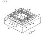
- FIG. 1 shows a perspective view of a gyroscope according to a preferred embodiment of the present invention
- FIG. 2 shows a floor plan of a gyroscope according to a preferred embodiment of the present invention
- FIG. 3 shows a magnified portion of FIG. 1
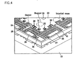
- FIG. 4 shows a partial SEM photograph of a gyroscope fabricated according to a preferred embodiment of the present invention.
- the gyroscope according to the preferred embodiment of the present invention comprises a glass substrate 10 and a silicon structure formed thereon. Supporting columns 11, 12, and 13 for supporting the silicon structure and fixing a fixture shaft of the silicon structure are formed on the glass substrate 10.
- the silicon structure comprises a driver, sensor, a plurality of springs, a tuning electrode 34, and a displacement limit shaft 33.
- the driver comprises a driving fixing electrode 26, a driving displacement electrode 24, and an inertial mass 23.
- the sensor comprises a sensing fixing electrode 25, a sensing displacement electrode 22, and an edge gimbal 21.
- the springs comprise driving springs 28 and 29 for supporting and allowing vibration of the driving displacement electrode 24, sensing springs 27 and 30 for supporting and allowing vibration of the sensing displacement electrode 22 and the edge gimbal 21, a driving connection spring 31 for connecting the driving displacement electrode 24 with the inertial mass 23, and a sensing connection spring 32 for connecting the sensing displacement electrode 22 with the inertial mass 23.
- the driving springs 28 and 29 are classified as an external driving spring 28 and an internal driving spring 29 respectively, and the sensing springs 27 and 30 are respectively an external sensing spring 27 and an internal sensing spring 30.
- the driving fixing electrode 26 of the driver is fixed by the supporting column 12 of the glass substrate 10 and has a spaced toothed portion.
- the driving displacement electrode 24 is supported by the external and internal driving springs 28 and 29, is movable only in the east to west direction (refer to the compass direction of FIGs. 1 and 2 ), and also has a spaced toothed portion.
- the teeth of the spaced toothed portion of the driving fixing electrode 26 and those of the driving displacement electrode 24 are interspersed with each other.
- the external and internal driving springs 28 and 29 are fixed by the supporting column 13 of the glass substrate 10, and since they are plate springs and are provided in the south to north direction, they are movable only in the east to west direction.
- the inertial mass 23 is connected to the driving displacement electrode 24 through the driving connection spring 31, when the driving displacement electrode 24 is vibrated in the east to west direction, the inertial mass 23 is vibrated together with the driving displacement electrode 24.
- the driving connection spring 31 since the driving connection spring 31 has no fixing shaft and can be movable only in the south to north direction, it delivers east to west vibration of the driving displacement electrode 24 to the inertial mass 23.
- the sensing fixing electrode 25 of the sensor fixed by the supporting column 12 of the glass substrate 10, has a spaced toothed portion.
- the sensing displacement electrode 22 is supported by the external and internal sensing springs 27 and 30, is movable only in the south to north direction (refer to the compass direction of FIGs. 1 and 2 ), and also has a spaced toothed portion.
- the teeth of the spaced toothed portion of the sensing fixing electrode 25 and those of the sensing displacement electrode 22 are interspersed with each other.
- the external and internal sensing springs 27 and 30 are fixed by the supporting column 13 of the glass substrate 10, and since they are plate springs and are provided in the east to west direction, they are movable only in the south to north direction.
- the sensing displacement electrode 22 is connected to the inertial mass 23 through the sensing connection spring 32, and accordingly, when the inertial mass 23 is vibrated in the south to north direction, the sensing displacement electrode 22 is vibrated together with the inertial mass 23.
- the sensing connection spring 32 since the sensing connection spring 32 has no fixing shaft and can be movable only in the east to west direction, the sensing connection spring 32 delivers the south to north directional vibration of the inertial mass 23 to the sensing displacement electrode 22 as it is.
- the edge gimbal 21 totally surrounds the driver and the sensor, and connects the sensing displacement electrodes 22 positioned on the south and north sides of the inertial mass 23. Therefore, the sensing displacement electrodes 22 on both sides are operated in the identical direction and with the identical displacement.
- Each tuning electrode 34 of a total of four, is formed on the east and west sides of the two south to north sensing displacement electrodes 22, and is fixed by a supporting column 11 of the glass substrate 10.
- a spaced toothed portion is formed on the tuning electrode's surface facing the sensing displacement electrodes 22, and a spaced tooth portion is also formed on the sensing displacement electrode's surface facing the tuning electrode 34.
- the teeth of the sensing displacement electrodes 22 face those of the tuning electrode 34, and the spaces of the sensing displacement electrodes 22 face those of the tuning electrode 34.
- the displacement limit shaft 33 formed in the center of a cavity formed in the center of the inertial mass 23, prevents the inertial mass 23 from being displaced over a predetermined level, and it is fixed by a supporting column (not illustrated) of the glass substrate 10. When the inertial mass 23 is stopped, the displacement limit shaft 33 is separated on one side from the inertial mass 23 by a predetermined gap.
- the driving displacement electrode 24 When power is supplied to the driving fixing electrode 26, the driving displacement electrode 24 is electrostatically driven according to the frequency of the power supplied to the driving fixing electrode 26, and it is vibrated in the east to west direction.
- the inertial mass 23 is also vibrated in the same manner of the driving displacement electrode 24.
- torque is applied to the gyroscope under this state, the inertial mass 23 receives the south to north directional force and is vibrated in the south to north direction.
- the south to north directional vibration of the inertial mass 23 is delivered to the sensing displacement electrode 22 as it is, and the sensing displacement electrodes 22 are vibrated in the same manner.
- the tuning electrode 34 functions as an electric spring, and it varies the resonance frequency of the sensing fixing electrode 25 to adjust sensing sensitivity.
- the displacement limit shaft 33 limits driving displacement of the inertial mass 23 within a uniform value so as to maintain a uniform displacement in a wide frequency range. This will be described subsequently.
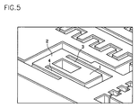
- FIG. 5 shows a magnified view of a driving or sensing spring of a gyroscope according to a preferred embodiment of the present invention
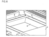
- FIG. 6 shows an SEM photograph of a driving or sensing spring of a gyroscope fabricated according to a preferred embodiment of the present invention.
- the driving or sensing spring comprises a fixture shaft 1, a connector 2, an internal plate 3 and an external plate 4.
- the fixture shaft 1 is fixed by the supporting column 13 of the glass substrate 10, and the connector 2 connects the internal plate 3 with the external plate 4.
- the internal plate 3 connects between the fixture shaft 1 and the connector 2, and the external plate 4 connects between the connector 2 and the driving or sensing displacement electrode (which is determined according to a driving spring or a sensing spring).
- the spring of this structure is referred to as a folded spring.
- the thin layer provided on the silicon structure is a metallic layer.
- This metallic layer is formed to perform flip chip bonding on the gyroscope.
- FIGs. 1 to 4 omit this illustration.
- the connector 2 and the cavity formed around the structure are used for injecting etchant when etching the glass substrate so as to raise the structure in the air in the fabrication process. Therefore, the cavities are formed on all portions of the structure except for the fixture shaft and the narrow spring plates 3 and 4.
- FIG. 7 shows a concept view of a driving or sensing connection spring of a gyroscope according to a preferred embodiment of the present invention.
- connection spring comprises a connector 2, an internal plate 3, and an external plate 4, and has no fixture shaft.
- the connector 2 connects the internal plate 3 with the external plate 4, and the internal plate 3 is connected to either a driving displacement electrode or a sensing displacement electrode (which is determined according to a driving connection spring or a sensing connection spring), and the external plate 4 is connected to the inertial mass 23.
- FIG. 8 shows a graph of resonance driving and sensing displacement according to a displacement limiter.
- the present gyroscope provides a mechanical displacement limiter for limiting driving displacement to the center portion of the inertial mass, so that the displacement of the inertial mass and the driver is maintained at a uniform value and uniform displacement is maintained in a wide frequency range. Also, as shown in FIG.
- the resonance frequency needs to be tuned in order to prevent lowering of sensitivity when the driving and sensing resonance frequencies are different because of process errors
- the driving displacement is uniformly maintained in the frequency range of wide driving displacement and the driving displacement is uniformly maintained in the sensing resonance frequency range, and hence, the gyroscope can be operated in the sensing resonance frequency without additional tuning.
- the driver and the sensor of the gyroscope structure adopt a combed structure, and are designed to minimize air damping by enlarging the gap from the ground surface and preserve a high Q value in atmospheric pressure so that a Q value equation that has not been considered in the design of conventional gyroscopes may be determined, and the Q value of the structure may be predicted based on the arrangement so as to maximize mechanical sensitivity. In this instance, Couette flow, Stokes flow, and squeeze damping are considered to predict the Q value.
- a maximal electrode structure is integrated in the given gyroscope region so as to have a large driving displacement of as much as 10 ⁇ m, and a corresponding mechanical structure is designed to minimize mechanical interference of the gyroscope and be insensitive to external noise.
- the driving and sensing frequencies of the structure are designed to be greater than 5kHz in order to remove influence of external noise, and the driving and sensing frequencies are designed not to be matched but to be separated by about 50Hz so as to enlarge the bandwidth.
- the driving and sensing frequencies are predicted to be 7,088Hz and 7,132Hz, respectively.
- a displacement limiter that artificially limits the displacement is attached to the gyroscope, which maintains the driving displacement in the wide frequency range to widen the bandwidth and reduces necessity of tuning.
- the gyroscope structure has a form basically identical with a two-dimensional stage, and a driving mode and a sensing mode exist in the identical plane. Since the sensitivity of the gyroscope increases as the inertial mass becomes greater, the whole mass of the gyroscope must be large. Also, the number of combed electrode structures in the structure is maximized in order to maximize the driving and sensing sensitivities, and edge gimbals are adopted in order to minimize mechanical interference.
- the size of the gyroscope structure is 8 x 8 mm 2 , and the whole size, considering an external frame for hermetic sealing, is 10 x 10 mm 2 . Single crystal silicon having excellent mechanical features is used as described above, and the thickness of the structure is designed to be 50 ⁇ m. Also, the gyroscope structure is floated above the glass substrate by 50 ⁇ m so as to reduce damping.
- damping value is to be calculated in order to calculate the Q value
- damping coefficients and equations for calculating them are as follows:
- the driver has 426 combed electrode structures and 6 folded spring structures for driving.
- the length of the spring is set to be 192 ⁇ m
- the spring coefficient is calculated to be 2,684 and the driving resonance frequency to be 8,299Hz.
- the Q factor in atmospheric pressure is calculated considering the size of the whole structure to be 3,565.
- the driving force and the driving displacement are calculated as follows.
- the detector has 692 combed electrode structures and 6 folded springs.
- the resonance frequency of the detector is 8,269Hz which is marginally less than the driving resonance frequency.
- the Q factor of the detector is calculated to be 3,765.
- the Coriolis force generated by an input angular rate and the corresponding displacement are calculated as follows.
- the mechanical sensitivity of the gyroscope is calculated to be 0.008[ ⁇ m(/deg/sec)], and the electrical sensitivity to be 1.939[fF/deg/sec].
- the gyroscope according to the present invention has 426 driving electrodes and 692 sensing electrodes, and the driving and sensing electrodes are mechanically separated from each other through the inertial mass. Also, the gyroscope has a displacement limiter provided in the center of the inertial mass for limiting displacement, and the maximum displacement is 15 ⁇ m. Further, a gimbal structure for reducing mechanical interference is provided on the outer portion of the element.
- the resonance frequencies range between 5,500 and 6,500Hz, and in particular, they are concentrated in the range between 5,500 and 6,000Hz.
- the difference between the two resonance frequencies is checked to be uniformly maintained to be about 50Hz.
- the spring is checked to have been broken or adhesion in a single direction to have been generated.
- the displacement at the time of resonance generates a value of less than the actual designed value as shown in Table 1, since the displacement is reduced because of the uni-directional driving, the air damping is increased and the value Q is reduced because the gap between the substrate and the structure is fabricated narrower than that of the designed one, and the gap between the combed electrodes is increased because of footing and undercut of the combed electrode structure.
- the driving voltage is artificially increased to check the efficiency of the displacement limiter.
- the driving displacement maximum of 15 ⁇ m is checked to be maintained in the range of several hundreds Hz, thereby allowing resistance to external noise and obtainment of wide bandwidths.
- the structure is designed so that it may have as many driving and sensing electrodes as possible and as large an inertial mass as possible so as to obtain great sensitivity in atmospheric pressure, and it may have a large driving operation displacement at high frequencies so as to remove influences caused by external noise.
- the gyroscope structure has the driving mode and the sensing mode on the same plane, it adopts an operation principle that can remove mechanical interference of the conventional gyroscope, and it has a perimeter gimbal structure so as to minimize mechanical interference.
- a displacement limiter for limiting driving displacement is mechanically added so as to provide a gyroscope that has quality sensitivity without additional frequency tuning and to design the operation bandwidth of the gyroscope to be increased.
- the fabricated gyroscope is operable in atmospheric pressure, and is very sensitive in atmospheric pressure.
Landscapes
- Engineering & Computer Science (AREA)
- Mechanical Engineering (AREA)
- Computer Hardware Design (AREA)
- Microelectronics & Electronic Packaging (AREA)
- Physics & Mathematics (AREA)
- General Physics & Mathematics (AREA)
- Radar, Positioning & Navigation (AREA)
- Remote Sensing (AREA)
- Gyroscopes (AREA)
Applications Claiming Priority (3)
| Application Number | Priority Date | Filing Date | Title |
|---|---|---|---|
| KR2001006695 | 2001-02-12 | ||
| KR10-2001-0006695A KR100418624B1 (ko) | 2001-02-12 | 2001-02-12 | 자이로스코프 및 그 제조 방법 |
| PCT/KR2002/000135 WO2002064497A1 (en) | 2001-02-12 | 2002-01-30 | Gyroscope and fabrication method thereof |
Publications (2)
| Publication Number | Publication Date |
|---|---|
| EP1360144A1 EP1360144A1 (en) | 2003-11-12 |
| EP1360144B1 true EP1360144B1 (en) | 2008-11-19 |
Family
ID=19705617
Family Applications (1)
| Application Number | Title | Priority Date | Filing Date |
|---|---|---|---|
| EP02711501A Expired - Lifetime EP1360144B1 (en) | 2001-02-12 | 2002-01-30 | Gyroscope and fabrication method thereof |
Country Status (8)
| Country | Link |
|---|---|
| US (1) | US6845668B2 (ko) |
| EP (1) | EP1360144B1 (ko) |
| JP (1) | JP3713019B2 (ko) |
| KR (1) | KR100418624B1 (ko) |
| CN (1) | CN1242913C (ko) |
| AT (1) | ATE414674T1 (ko) |
| DE (1) | DE60229919D1 (ko) |
| WO (1) | WO2002064497A1 (ko) |
Families Citing this family (26)
| Publication number | Priority date | Publication date | Assignee | Title |
|---|---|---|---|---|
| US6927098B2 (en) * | 2003-05-07 | 2005-08-09 | Honeywell International Inc. | Methods and apparatus for attaching MEMS devices to housing |
| US7037805B2 (en) | 2003-05-07 | 2006-05-02 | Honeywell International Inc. | Methods and apparatus for attaching a die to a substrate |
| SG112898A1 (en) * | 2003-12-11 | 2005-07-28 | Singapore Tech Dynamics Pte | Sensing apparatus, system and method |
| JP2005326620A (ja) * | 2004-05-14 | 2005-11-24 | Fujitsu Ltd | マイクロミラー素子 |
| CN100338470C (zh) * | 2005-03-25 | 2007-09-19 | 中北大学 | 单片双惯性参数加速度计陀螺仪 |
| JP5070778B2 (ja) * | 2006-09-20 | 2012-11-14 | 株式会社デンソー | 力学量センサ |
| US8061201B2 (en) * | 2007-07-13 | 2011-11-22 | Georgia Tech Research Corporation | Readout method and electronic bandwidth control for a silicon in-plane tuning fork gyroscope |
| US9171964B2 (en) | 2010-11-23 | 2015-10-27 | Honeywell International Inc. | Systems and methods for a three-layer chip-scale MEMS device |
| US9493344B2 (en) | 2010-11-23 | 2016-11-15 | Honeywell International Inc. | MEMS vertical comb structure with linear drive/pickoff |
| US8748206B2 (en) | 2010-11-23 | 2014-06-10 | Honeywell International Inc. | Systems and methods for a four-layer chip-scale MEMS device |
| US8776601B2 (en) | 2010-11-23 | 2014-07-15 | Honeywell International Inc. | MEMS sensor using multi-layer movable combs |
| CN102507981B (zh) * | 2011-11-02 | 2013-06-05 | 重庆理工大学 | 一种带耦合梁结构的单敏感质量元硅微二维加速度传感器 |
| CN102633227B (zh) * | 2012-03-16 | 2014-07-23 | 中北大学 | 一种mems惯性传感器结构压膜阻尼可调装置 |
| US9581447B2 (en) * | 2014-07-08 | 2017-02-28 | Honeywell International Inc. | MEMS gyro motor loop filter |
| US9903718B2 (en) * | 2015-05-28 | 2018-02-27 | Invensense, Inc. | MEMS device mechanical amplitude control |
| US10514259B2 (en) | 2016-08-31 | 2019-12-24 | Analog Devices, Inc. | Quad proof mass MEMS gyroscope with outer couplers and related methods |
| US10627235B2 (en) | 2016-12-19 | 2020-04-21 | Analog Devices, Inc. | Flexural couplers for microelectromechanical systems (MEMS) devices |
| US10697774B2 (en) | 2016-12-19 | 2020-06-30 | Analog Devices, Inc. | Balanced runners synchronizing motion of masses in micromachined devices |
| US10415968B2 (en) | 2016-12-19 | 2019-09-17 | Analog Devices, Inc. | Synchronized mass gyroscope |
| FR3065800B1 (fr) * | 2017-04-27 | 2019-08-02 | Safran | Resonateur configure pour etre integre a un capteur angulaire inertiel |
| US10948294B2 (en) | 2018-04-05 | 2021-03-16 | Analog Devices, Inc. | MEMS gyroscopes with in-line springs and related systems and methods |
| US11193771B1 (en) | 2020-06-05 | 2021-12-07 | Analog Devices, Inc. | 3-axis gyroscope with rotational vibration rejection |
| US11686581B2 (en) | 2020-06-08 | 2023-06-27 | Analog Devices, Inc. | Stress-relief MEMS gyroscope |
| WO2021252398A1 (en) | 2020-06-08 | 2021-12-16 | Analog Devices, Inc. | Drive and sense stress relief apparatus |
| US11698257B2 (en) | 2020-08-24 | 2023-07-11 | Analog Devices, Inc. | Isotropic attenuated motion gyroscope |
| CN113135548A (zh) * | 2021-04-20 | 2021-07-20 | 广州蜂鸟传感科技有限公司 | 一种压电微机械执行器 |
Citations (4)
| Publication number | Priority date | Publication date | Assignee | Title |
|---|---|---|---|---|
| US5728936A (en) * | 1995-08-16 | 1998-03-17 | Robert Bosch Gmbh | Rotary speed sensor |
| US5914521A (en) * | 1997-07-30 | 1999-06-22 | Motorola, Inc. | Sensor devices having a movable structure |
| US5945599A (en) * | 1996-12-13 | 1999-08-31 | Kabushiki Kaisha Toyota Chuo Kenkyusho | Resonance type angular velocity sensor |
| US6122961A (en) * | 1997-09-02 | 2000-09-26 | Analog Devices, Inc. | Micromachined gyros |
Family Cites Families (3)
| Publication number | Priority date | Publication date | Assignee | Title |
|---|---|---|---|---|
| KR100231715B1 (ko) | 1997-11-25 | 1999-11-15 | 정선종 | 평면 진동형 마이크로 자이로스코프 |
| KR100316774B1 (ko) | 1999-01-15 | 2001-12-12 | 이형도 | 마이크로 관성 센서의 제작 방법 |
| US6481285B1 (en) | 1999-04-21 | 2002-11-19 | Andrei M. Shkel | Micro-machined angle-measuring gyroscope |
-
2001
- 2001-02-12 KR KR10-2001-0006695A patent/KR100418624B1/ko active IP Right Grant
-
2002
- 2002-01-30 US US10/257,532 patent/US6845668B2/en not_active Expired - Fee Related
- 2002-01-30 JP JP2002564435A patent/JP3713019B2/ja not_active Expired - Fee Related
- 2002-01-30 AT AT02711501T patent/ATE414674T1/de not_active IP Right Cessation
- 2002-01-30 WO PCT/KR2002/000135 patent/WO2002064497A1/en active Application Filing
- 2002-01-30 DE DE60229919T patent/DE60229919D1/de not_active Expired - Fee Related
- 2002-01-30 EP EP02711501A patent/EP1360144B1/en not_active Expired - Lifetime
- 2002-01-30 CN CNB028002954A patent/CN1242913C/zh not_active Expired - Fee Related
Patent Citations (4)
| Publication number | Priority date | Publication date | Assignee | Title |
|---|---|---|---|---|
| US5728936A (en) * | 1995-08-16 | 1998-03-17 | Robert Bosch Gmbh | Rotary speed sensor |
| US5945599A (en) * | 1996-12-13 | 1999-08-31 | Kabushiki Kaisha Toyota Chuo Kenkyusho | Resonance type angular velocity sensor |
| US5914521A (en) * | 1997-07-30 | 1999-06-22 | Motorola, Inc. | Sensor devices having a movable structure |
| US6122961A (en) * | 1997-09-02 | 2000-09-26 | Analog Devices, Inc. | Micromachined gyros |
Also Published As
| Publication number | Publication date |
|---|---|
| US6845668B2 (en) | 2005-01-25 |
| KR20020066486A (ko) | 2002-08-19 |
| WO2002064497A1 (en) | 2002-08-22 |
| CN1457319A (zh) | 2003-11-19 |
| JP3713019B2 (ja) | 2005-11-02 |
| DE60229919D1 (ko) | 2009-01-02 |
| CN1242913C (zh) | 2006-02-22 |
| JP2004518964A (ja) | 2004-06-24 |
| ATE414674T1 (de) | 2008-12-15 |
| US20030159509A1 (en) | 2003-08-28 |
| EP1360144A1 (en) | 2003-11-12 |
| KR100418624B1 (ko) | 2004-02-11 |
Similar Documents
| Publication | Publication Date | Title |
|---|---|---|
| EP1360144B1 (en) | Gyroscope and fabrication method thereof | |
| US6257059B1 (en) | Microfabricated tuning fork gyroscope and associated three-axis inertial measurement system to sense out-of-plane rotation | |
| EP0604519B1 (en) | Micromechanical tuning fork angular rate sensor | |
| US7250112B2 (en) | Method of making an X-Y axis dual-mass tuning fork gyroscope with vertically integrated electronics and wafer-scale hermetic packaging | |
| US7621183B2 (en) | X-Y axis dual-mass tuning fork gyroscope with vertically integrated electronics and wafer-scale hermetic packaging | |
| US8739626B2 (en) | Micromachined inertial sensor devices | |
| US7484410B2 (en) | Gyro sensor and sensor apparatus using same | |
| JP3950925B2 (ja) | マイクロメカニック回転速度センサ | |
| JP5450451B2 (ja) | 垂直方向に集積した電子回路およびウェハスケール密封包装を含むx−y軸二重質量音叉ジャイロスコープ | |
| WO2009130554A2 (en) | X-y axis dual-mass tuning fork gyroscope with vertically integrated electronics and wafer-scale hermetic packaging | |
| US9273962B2 (en) | Physical quantity sensor and electronic device | |
| US20230314469A1 (en) | Mems tri-axial accelerometer with one or more decoupling elements | |
| JP4654667B2 (ja) | ジャイロセンサおよび角速度検出方法 | |
| JP3421340B2 (ja) | 強誘電薄膜進行波回転センサ | |
| JP3230331B2 (ja) | 角速度センサ | |
| JPH09325032A (ja) | 角速度センサ | |
| KR100880212B1 (ko) | 자이로 센서 및 이를 이용하는 센서 장치 |
Legal Events
| Date | Code | Title | Description |
|---|---|---|---|
| PUAI | Public reference made under article 153(3) epc to a published international application that has entered the european phase |
Free format text: ORIGINAL CODE: 0009012 |
|
| 17P | Request for examination filed |
Effective date: 20020920 |
|
| AK | Designated contracting states |
Kind code of ref document: A1 Designated state(s): AT BE CH CY DE DK ES FI FR GB GR IE IT LI LU MC NL PT SE TR |
|
| AX | Request for extension of the european patent |
Extension state: AL LT LV MK RO SI |
|
| 17Q | First examination report despatched |
Effective date: 20061006 |
|
| 17Q | First examination report despatched |
Effective date: 20061006 |
|
| GRAP | Despatch of communication of intention to grant a patent |
Free format text: ORIGINAL CODE: EPIDOSNIGR1 |
|
| GRAS | Grant fee paid |
Free format text: ORIGINAL CODE: EPIDOSNIGR3 |
|
| GRAA | (expected) grant |
Free format text: ORIGINAL CODE: 0009210 |
|
| AK | Designated contracting states |
Kind code of ref document: B1 Designated state(s): AT BE CH CY DE DK ES FI FR GB GR IE IT LI LU MC NL PT SE TR |
|
| REG | Reference to a national code |
Ref country code: GB Ref legal event code: FG4D |
|
| REG | Reference to a national code |
Ref country code: CH Ref legal event code: EP |
|
| REG | Reference to a national code |
Ref country code: IE Ref legal event code: FG4D |
|
| REF | Corresponds to: |
Ref document number: 60229919 Country of ref document: DE Date of ref document: 20090102 Kind code of ref document: P |
|
| PG25 | Lapsed in a contracting state [announced via postgrant information from national office to epo] |
Ref country code: AT Free format text: LAPSE BECAUSE OF FAILURE TO SUBMIT A TRANSLATION OF THE DESCRIPTION OR TO PAY THE FEE WITHIN THE PRESCRIBED TIME-LIMIT Effective date: 20081119 Ref country code: ES Free format text: LAPSE BECAUSE OF FAILURE TO SUBMIT A TRANSLATION OF THE DESCRIPTION OR TO PAY THE FEE WITHIN THE PRESCRIBED TIME-LIMIT Effective date: 20090301 |
|
| NLV1 | Nl: lapsed or annulled due to failure to fulfill the requirements of art. 29p and 29m of the patents act | ||
| PG25 | Lapsed in a contracting state [announced via postgrant information from national office to epo] |
Ref country code: NL Free format text: LAPSE BECAUSE OF FAILURE TO SUBMIT A TRANSLATION OF THE DESCRIPTION OR TO PAY THE FEE WITHIN THE PRESCRIBED TIME-LIMIT Effective date: 20081119 Ref country code: FI Free format text: LAPSE BECAUSE OF FAILURE TO SUBMIT A TRANSLATION OF THE DESCRIPTION OR TO PAY THE FEE WITHIN THE PRESCRIBED TIME-LIMIT Effective date: 20081119 |
|
| PG25 | Lapsed in a contracting state [announced via postgrant information from national office to epo] |
Ref country code: DK Free format text: LAPSE BECAUSE OF FAILURE TO SUBMIT A TRANSLATION OF THE DESCRIPTION OR TO PAY THE FEE WITHIN THE PRESCRIBED TIME-LIMIT Effective date: 20081119 Ref country code: BE Free format text: LAPSE BECAUSE OF FAILURE TO SUBMIT A TRANSLATION OF THE DESCRIPTION OR TO PAY THE FEE WITHIN THE PRESCRIBED TIME-LIMIT Effective date: 20081119 |
|
| PG25 | Lapsed in a contracting state [announced via postgrant information from national office to epo] |
Ref country code: PT Free format text: LAPSE BECAUSE OF FAILURE TO SUBMIT A TRANSLATION OF THE DESCRIPTION OR TO PAY THE FEE WITHIN THE PRESCRIBED TIME-LIMIT Effective date: 20090420 Ref country code: MC Free format text: LAPSE BECAUSE OF NON-PAYMENT OF DUE FEES Effective date: 20090131 Ref country code: SE Free format text: LAPSE BECAUSE OF FAILURE TO SUBMIT A TRANSLATION OF THE DESCRIPTION OR TO PAY THE FEE WITHIN THE PRESCRIBED TIME-LIMIT Effective date: 20090219 |
|
| REG | Reference to a national code |
Ref country code: CH Ref legal event code: PL |
|
| PLBE | No opposition filed within time limit |
Free format text: ORIGINAL CODE: 0009261 |
|
| STAA | Information on the status of an ep patent application or granted ep patent |
Free format text: STATUS: NO OPPOSITION FILED WITHIN TIME LIMIT |
|
| 26N | No opposition filed |
Effective date: 20090820 |
|
| GBPC | Gb: european patent ceased through non-payment of renewal fee |
Effective date: 20090219 |
|
| PG25 | Lapsed in a contracting state [announced via postgrant information from national office to epo] |
Ref country code: CH Free format text: LAPSE BECAUSE OF NON-PAYMENT OF DUE FEES Effective date: 20090131 Ref country code: DE Free format text: LAPSE BECAUSE OF NON-PAYMENT OF DUE FEES Effective date: 20090801 Ref country code: LI Free format text: LAPSE BECAUSE OF NON-PAYMENT OF DUE FEES Effective date: 20090131 |
|
| REG | Reference to a national code |
Ref country code: FR Ref legal event code: ST Effective date: 20091030 |
|
| PG25 | Lapsed in a contracting state [announced via postgrant information from national office to epo] |
Ref country code: IE Free format text: LAPSE BECAUSE OF NON-PAYMENT OF DUE FEES Effective date: 20090130 |
|
| PG25 | Lapsed in a contracting state [announced via postgrant information from national office to epo] |
Ref country code: FR Free format text: LAPSE BECAUSE OF NON-PAYMENT OF DUE FEES Effective date: 20090202 Ref country code: GB Free format text: LAPSE BECAUSE OF NON-PAYMENT OF DUE FEES Effective date: 20090219 |
|
| PG25 | Lapsed in a contracting state [announced via postgrant information from national office to epo] |
Ref country code: GR Free format text: LAPSE BECAUSE OF FAILURE TO SUBMIT A TRANSLATION OF THE DESCRIPTION OR TO PAY THE FEE WITHIN THE PRESCRIBED TIME-LIMIT Effective date: 20090220 |
|
| PG25 | Lapsed in a contracting state [announced via postgrant information from national office to epo] |
Ref country code: IT Free format text: LAPSE BECAUSE OF FAILURE TO SUBMIT A TRANSLATION OF THE DESCRIPTION OR TO PAY THE FEE WITHIN THE PRESCRIBED TIME-LIMIT Effective date: 20081119 |
|
| PG25 | Lapsed in a contracting state [announced via postgrant information from national office to epo] |
Ref country code: LU Free format text: LAPSE BECAUSE OF NON-PAYMENT OF DUE FEES Effective date: 20090130 |
|
| PG25 | Lapsed in a contracting state [announced via postgrant information from national office to epo] |
Ref country code: TR Free format text: LAPSE BECAUSE OF FAILURE TO SUBMIT A TRANSLATION OF THE DESCRIPTION OR TO PAY THE FEE WITHIN THE PRESCRIBED TIME-LIMIT Effective date: 20081119 |
|
| PG25 | Lapsed in a contracting state [announced via postgrant information from national office to epo] |
Ref country code: CY Free format text: LAPSE BECAUSE OF FAILURE TO SUBMIT A TRANSLATION OF THE DESCRIPTION OR TO PAY THE FEE WITHIN THE PRESCRIBED TIME-LIMIT Effective date: 20081119 |