EP1360053B1 - Positioning of a covering in a mould - Google Patents
Positioning of a covering in a mould Download PDFInfo
- Publication number
- EP1360053B1 EP1360053B1 EP02716163A EP02716163A EP1360053B1 EP 1360053 B1 EP1360053 B1 EP 1360053B1 EP 02716163 A EP02716163 A EP 02716163A EP 02716163 A EP02716163 A EP 02716163A EP 1360053 B1 EP1360053 B1 EP 1360053B1
- Authority
- EP
- European Patent Office
- Prior art keywords
- covering
- mould
- positioning tool
- stitch line
- tool
- Prior art date
- Legal status (The legal status is an assumption and is not a legal conclusion. Google has not performed a legal analysis and makes no representation as to the accuracy of the status listed.)
- Expired - Lifetime
Links
Images


Classifications
-
- B—PERFORMING OPERATIONS; TRANSPORTING
- B29—WORKING OF PLASTICS; WORKING OF SUBSTANCES IN A PLASTIC STATE IN GENERAL
- B29C—SHAPING OR JOINING OF PLASTICS; SHAPING OF MATERIAL IN A PLASTIC STATE, NOT OTHERWISE PROVIDED FOR; AFTER-TREATMENT OF THE SHAPED PRODUCTS, e.g. REPAIRING
- B29C44/00—Shaping by internal pressure generated in the material, e.g. swelling or foaming ; Producing porous or cellular expanded plastics articles
- B29C44/02—Shaping by internal pressure generated in the material, e.g. swelling or foaming ; Producing porous or cellular expanded plastics articles for articles of definite length, i.e. discrete articles
- B29C44/12—Incorporating or moulding on preformed parts, e.g. inserts or reinforcements
- B29C44/14—Incorporating or moulding on preformed parts, e.g. inserts or reinforcements the preformed part being a lining
- B29C44/143—Means for positioning the lining in the mould
Definitions
- This invention relates to a method according to the preamble of claim 1 for making a foamed component comprising a covering, particularly but not exclusively a vehicle interior component.
- Such a method is known eg from GB-A-2 175 242.
- foam in place When manufacturing components for vehicle interiors, a common processing technique referred to as "foam in place" is used, wherein a covering comprising a plastic moulded skin is placed in a foaming tool. A rigid armature is held spaced from the skin by the foaming tool and polyurethane foam is injected between the covering and the armature to provide a component with a soft feel foam interlayer supported by the armature.
- foam in place When manufacturing such a component, positioning of the moulded skin in the foaming tool is simple since the skin is formed in the shape of the final part and the foaming tool is appropriately shaped to receive the skin.
- An aim of the invention is to reduce or overcome one or more of the above problems.
- the present invention provides a method as defined in claim 1.
- the method may comprise the step, when the covering is placed on the positioning tool, of holding the covering in position adjacent the positioning tool by means of a first holding means.
- the method may comprise the step, after inserting the positioning tool in the mould, of releasing the first holding means to release the covering from the positioning tool, and operating a second holding means to hold the covering in position in said mould.
- the method may comprise the step of disposing an armature in the mould prior to closing the mould.
- the covering may comprise a first part and a second part each having an outer surface, an edge part of each of the said first part and said second part being disposed adjacent one another such that the outer surfaces are in abutment and such that stitches pass through said edge part to form the stitch line.
- the stitch line may further comprise a tape element extending along said stitch line on the reverse side of the covering, the tape element being attached to the first part and/or the second part either side of the stitch line.
- the projecting part may comprise a profile held in place by said tape element.
- the stitch line may be resistant to passage of foam.
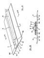
- the positioning tool 10 comprises support means having a head part 12 a and a surface part 12 b , the surface part 12 b being provided with first holding means 12 c in the form of a vacuum source extending to apertures on the surface of the surface part 12 b .
- the head part 12 a along an edge thereof is provided with a recess 13, in the present example a groove extending along the length of the head part 12 a .
- the positioning tool 10 is adapted to receive and support a covering 14 for location in the mould 11.
- the covering 14 comprises a first part 14 a and a second part 14 b , the first part 14 a and second part 14 b being joined along a stitch line 15.
- the stitch line 15 may be formed in any suitable manner as described, and particularly as described hereinafter.
- the covering 14 has an outer surface 16, which will be visible on the completed component, and an inner, or reverse, surface 17 which faces inwardly of the completed component.
- the covering 14 is mounted on the positioning tool 10 such that a projecting part 18 formed by the stitch line 15 is snugly received in the recess 13.
- the first part 14a of the covering 14 is disposed with the inner surface 17 adjacent the surface part 12 b , such that when the first holding means 12 c is operated, the covering 14 is held adjacent the surface part 12 b .
- the covering 14 is further provided with a plurality of locating apertures 19 disposed towards the periphery thereof.
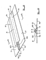
- the foaming tool 11 comprises a lower mould part 20 and an upper mould part 21.
- the upper mould part 21 is pivotally connected to the lower mould part 20 by hinges generally indicated at 22.
- a foam supply means (not shown) to supply foam to the foaming tool is provided.
- the lower mould part 20 is provided with a lower mould surface 23 in the shape of the outer surface of the desired component.
- the desired component forms part of a dashboard assembly for the interior of a vehicle.
- the lower mould surface 23 is provided with an undercut 24.
- the head part 12 a of the positioning tool 10 is shaped to conform to the shape of and be received within the undercut 24 of the lower mould surface 23, with allowances for the thickness of the covering 14.
- the lower mould surface 23 is provided with second holding means (not shown), for example vacuum means, to hold the covering 14 in place adjacent to the lower mould surface 23.
- the lower mould part 20 is further provided with a plurality of location pins 25 located around the periphery of the lower mould surface 23, the location pins 25 being adapted to engage the location holes 19 on the covering 14.
- the upper mould part 21 is provided with holding means (not shown) to support an armature at an appropriate spacing from the lower mould surface 23.
- the support positioning tool 10 in the present example conforms to the shape of the lower mould surface 23 only in the vicinity of the recess 13, that is only the head part 12 a is so shaped, to permit easy introduction and withdrawal of the positioning tool 10. It will be apparent that, where appropriate, the head part 12 a may be provided without a recess 13, but the shape of the head part 12 a will similarly advantageously permit easy location and withdrawal of the positioning tool 10.
- an operator To manufacture a component, an operator first places a covering 14 having a projecting part 18 onto the positioning tool 10 such that the projecting part 18 is received in the recess 13. By actuation of the holding means 12 c , the covering 14 is held adjacent the positing tool 10 in the correct position. The operator then positions the positioning tool 10 in the lower mould part 21, such that the head part 12 a of the positioning tool is received in the undercut 24. The operator locates the locating pins 25 in the corresponding locating holes 19 in the covering 14. If the holes and pins are not correctly aligned, this indicates that either the covering 14 or tool 10 is not correctly positioned, and then it will then be apparent to the operator that the tool 10 or the covering 14 needs to be repositioned.
- the holding means of the lower mould part 21 are activated to hold the covering 14 in position adjacent the lower mould surface 23.
- the holding means 12 c may then be deactivated, for example by releasing the vacuum, to release the covering 14 from the positioning tool 10.
- the positioning tool 10 may then be withdrawn from the lower mould part 21.
- the engagement of the pins 25 and holes 19 also helps to keep the covering 14 in place while the positioning tool 10 is withdrawn.
- the covering 14 is held in place with the outer surface 16 facing downwardly, adjacent the lower mould surface 23, and with the inner surface 17 facing upwardly.
- the geometry of the head part 12 a of the positioning tool 10 and of the undercut 24 is such that the tool may be withdrawn from the mould without difficulty.
- the positioning tool 10 may be collapsible to permit easy removal of the tool 10 once the covering 14 has been positioned.
- the effect of performing this method is that the stitch line 15 is correctly positioned relative to the lower mould part 23.
- the stitch line 15 can thus be repeatedly and easily located in the correct position without demanding a great deal of skill from the operator.
- the armature is located on the upper mould part 21.
- a foaming material is dispersed directly on top of the covering 14 by the foam supply means.
- the tool 11 is then closed, by pivoting the upper part 21 of the mould about hinges 22 down to a closed position.
- the foaming tool 11 applies a desired pressure while the foaming material sets.
- the foaming tool 11 may be closed prior to introducing the foaming material, and foaming material introduced via the foam supply means.
- the foaming material is introduced between the covering and armature.
- the component now comprising a covering 14 bonded to an armature by a layer of foam material, may be withdrawn from the tool 11 and the process repeated.
- further positioning means such as hinge or dowels may be provided to locate the positioning tool 10 relative to the lower mould part 23.
- the dowels or other means may be omitted.
- the method and apparatus are intended to be used with leather or material having the appearance of leather such as leatherette, although other material where suitable may be used as desired.
- the projecting part 18 of the stitch line 15 be of a suitable size and shape to be correctly received within the recess 13. Examples of two such projecting parts are shown in Figures 5 a , 5 b , 6 a , 6 b .
- the two parts 14 a , 14 b , of the covering 14 are joined at a stitch line 15.
- the first part 14 a and second part 14 b are joined together along the stitch line 15 such that the selvage 30 a , 30 b of each part, i.e. that edge part of the material extending beyond the stitch line 15, will be disposed within the final component out of view, adjacent to the inner surface 17.
- a profile Disposed above the stitch line 15 and running parallel thereto is a profile, in the present example comprising a length of piping 31.
- the profile may alternatively comprise rope, or wire, or may be other material as appropriate or desired.
- the length of piping 31 is held in place by a tape envelope 32 which extends alongside the stitch line 15.
- the piping 31 is disposed within a generally central part of the envelope 32.
- the envelope 32 is then held in place by stitch lines 33 extending either side of the piping 31 and passing through the envelope 32 and at least one of the first part 14 a and second part 14 b as appropriate.
- a projecting part 18 is formed on the inner, or reverse, surface 17 of the covering 14 which may be received in the recess 13.
- the piping may be omitted as shown in Figures 6 a and 6 b .
- the parts 14 a and 14 b are likewise joined by a stitch line, but instead of being folded back to lie alongside the parts 14 a , 14 b , the selvage 30' a , 30' b , as seen in Figures 6 b extends generally transverse to the part 14 a , 14 b .
- a tape part 34 is disposed on the inner surface 17 of the part 14, a side part 35 of the tape 34 disposed each side of the stitch line 15 and lying adjacent to the part 14 a , 14 b , with a central part 36 of the tape 34 extending over the stitch line 15.
- the tape 34 is then held in place by stitch lines 37 passing through at least one of the first part 14 a and second part 14 b either side of the stitch line 15.
- a stitch line 15 as described hereinbefore has the further advantage that when the covering 14 is located in the foaming tool 11 and foam is supplied to the mould, the stitch line 15, and in particular the tape element 34, resists the passage of foam through the stitch line 15.
- the feature 18 may be formed by any means as desired. It will also be apparent that the method and apparatus may be used to manufacture any appropriate component as desired and may be applied to location of a covering in a mould for any application of purpose as necessary.
Landscapes
- Casting Or Compression Moulding Of Plastics Or The Like (AREA)
- Moulds For Moulding Plastics Or The Like (AREA)
- Vehicle Interior And Exterior Ornaments, Soundproofing, And Insulation (AREA)
Description
Claims (11)
- A method of making a component comprising the steps of providing a covering (14), having an outer surface (16) and an inner, reverse surface (17) the covering (14) comprising a projecting part (18), placing said covering (14) on a positioning tool (10), locating said covering in a mould (11) using said positioning tool (10), removing the positioning tool (10) from the mould (11) leaving the covering (14) in place in the mould (11), closing the mould (11), and supplying foam to the mould (11), characterised in that the method comprises the steps of providing a covering (14) with a stitch line (15) on the reverse surface of the covering (14) to provide the projecting part (18) and locating the projecting part (18) in a groove of said positioning tool (10).
- A method according to claim 1 comprising the step, when the covering (14) is placed on the positioning tool, of holding the covering (14) in position adjacent the positioning tool by means of a first holding means.
- A method according to claim 2 comprising the step, after inserting the positioning tool in the mould (11), of releasing the first holding means to release the covering (14) from the positioning tool, and operating a second holding means to hold the covering (14) in position in said mould (11).
- A method according to any one of claims 1 to 3 comprising the step of disposing an armature in the mould (11) prior to closing the mould (11).
- A method according to any one of the preceding claims wherein the mould (11) has a first mould part (20) and a second mould part (21), the second mould part (21) being movable relative to the first mould part (20), wherein the positioning tool (10) is shaped to co-operate with said at least one mould part.
- A method according to claim 5 wherein the positioning tool (10) is shaped co-operate with said at least one mould part only in the vicinity of the groove (13).
- A method according to claim 5 or claim 6 wherein the positioning tool (10) comprises a head part (12a) and a surface part (12b) extending away from said head part (12a) and wherein the groove (13) is provided on the head part (12a).
- A method according to any one of the preceding claims comprising providing the covering (14) having a first part (14a) and a second part (14b) each having an outer surface, an edge part (30a, 30b) of each of the said first part and said second part being disposed adjacent one another such that the outer surfaces are in abutment and such that stitches pass through said edge part to form the stitch line (15).
- A method according to claim 8 wherein the projecting part (18) further comprises a tape element (34) extending along said stitch line on the reverse side of the covering, the tape element (34) being attached to the first part (14a) and/or the second part (14b) either side of the stitch line (15).
- A method according to claim 9 wherein the projecting part comprises a profile (31) held in place by said tape element (34).
- A method according to claim 9 or claim 10 wherein the stitch line (15) is resistant to passage of foam.
Applications Claiming Priority (3)
| Application Number | Priority Date | Filing Date | Title |
|---|---|---|---|
| GB0102201A GB2373751A (en) | 2001-01-27 | 2001-01-27 | A mould with a tool for positioning a covering within the mould |
| GB0102201 | 2001-01-27 | ||
| PCT/GB2002/000319 WO2002058906A1 (en) | 2001-01-27 | 2002-01-25 | Positioning covering in a mould |
Publications (2)
| Publication Number | Publication Date |
|---|---|
| EP1360053A1 EP1360053A1 (en) | 2003-11-12 |
| EP1360053B1 true EP1360053B1 (en) | 2005-06-01 |
Family
ID=9907675
Family Applications (1)
| Application Number | Title | Priority Date | Filing Date |
|---|---|---|---|
| EP02716163A Expired - Lifetime EP1360053B1 (en) | 2001-01-27 | 2002-01-25 | Positioning of a covering in a mould |
Country Status (6)
| Country | Link |
|---|---|
| US (1) | US20040086589A1 (en) |
| EP (1) | EP1360053B1 (en) |
| CA (1) | CA2435879A1 (en) |
| DE (1) | DE60204424T2 (en) |
| GB (1) | GB2373751A (en) |
| WO (1) | WO2002058906A1 (en) |
Family Cites Families (10)
| Publication number | Priority date | Publication date | Assignee | Title |
|---|---|---|---|---|
| JPS606208B2 (en) * | 1979-02-14 | 1985-02-16 | 池田物産株式会社 | Method for manufacturing integral foam sheet with buttons |
| GB2175242A (en) * | 1985-05-09 | 1986-11-26 | Ford Motor Co | Method of manufacturing a seat pad |
| DE3622951A1 (en) * | 1986-07-09 | 1988-01-21 | Bayer Ag | METHOD AND MOLDING TOOL FOR MAKING FOAM UPHOLSTERY FABRIC WITH TEXTILE COVERS |
| JPS6345007A (en) * | 1986-08-12 | 1988-02-26 | Ikeda Bussan Co Ltd | Molding of foam integrated with skin |
| DE3634297C1 (en) * | 1986-10-08 | 1987-09-17 | Grammer Sitzsysteme Gmbh | Process for producing a foam-backed upholstery part |
| DE3743318C1 (en) * | 1987-08-22 | 1988-12-01 | Grammer Sitzsysteme Gmbh | Apparatus for producing a foam-backed upholstery part |
| JP2988957B2 (en) * | 1990-04-04 | 1999-12-13 | アラコ株式会社 | Method of fixing seat cover in sheet mold and sheet mold |
| US5231745A (en) * | 1991-07-12 | 1993-08-03 | Atoma International Inc. | Method of making a cover and foam body seat component |
| DE4235769A1 (en) * | 1992-10-23 | 1994-04-28 | Riesselmann & Sohn | Prodn. of plastic carrier with decorative layer and prodn. mould - involves placing decorative layer in tool cavity, turning up and folding back end section to form pocket filled by injected plastic forming carrier |
| US5452939A (en) * | 1993-08-09 | 1995-09-26 | Hoover Universal, Inc. | Upholstery cover and method for positively locating cover during foam molding |
-
2001
- 2001-01-27 GB GB0102201A patent/GB2373751A/en not_active Withdrawn
-
2002
- 2002-01-25 WO PCT/GB2002/000319 patent/WO2002058906A1/en not_active Ceased
- 2002-01-25 EP EP02716163A patent/EP1360053B1/en not_active Expired - Lifetime
- 2002-01-25 DE DE60204424T patent/DE60204424T2/en not_active Expired - Lifetime
- 2002-01-25 US US10/470,482 patent/US20040086589A1/en not_active Abandoned
- 2002-01-25 CA CA002435879A patent/CA2435879A1/en not_active Abandoned
Also Published As
| Publication number | Publication date |
|---|---|
| GB0102201D0 (en) | 2001-03-14 |
| DE60204424D1 (en) | 2005-07-07 |
| CA2435879A1 (en) | 2002-08-01 |
| US20040086589A1 (en) | 2004-05-06 |
| GB2373751A (en) | 2002-10-02 |
| EP1360053A1 (en) | 2003-11-12 |
| WO2002058906A1 (en) | 2002-08-01 |
| DE60204424T2 (en) | 2005-10-27 |
Similar Documents
| Publication | Publication Date | Title |
|---|---|---|
| US5941557A (en) | Air bag cover door with tether | |
| US5509990A (en) | Process for producing a multilayer molded article | |
| EP1820625B1 (en) | Manufacturing of vehicular interior parts | |
| KR950005711B1 (en) | Manufacturing method of interior panel of car door | |
| US6505570B1 (en) | Method for forming a foamed product integral with trim cover assembly | |
| US6663734B2 (en) | Method for forming a foamed product integral with trim cover assembly | |
| US5452939A (en) | Upholstery cover and method for positively locating cover during foam molding | |
| JPH0596655A (en) | Method for forming a vehicle seat having a surface of a predetermined shape | |
| CA2173766A1 (en) | Vehicle trim panel | |
| US20110214803A1 (en) | Vacuum thermoforming of thermoplastic sheets with decorative inserts | |
| US20040086589A1 (en) | Positioning covering in a mould | |
| EP2386398B1 (en) | A method for producing a foamed article | |
| US5290093A (en) | Method of seam location using vacuum | |
| US20090085237A1 (en) | Method and apparatus for tensioning coverstock and forming vehicle interior components | |
| WO2009045202A1 (en) | Methods of tensioning coverstock and forming vehicle interior components | |
| US12441069B2 (en) | Method of manufacturing a trim panel | |
| JP2000326343A (en) | Manufacture of ornamental assembly having graining line | |
| JP2008521641A (en) | Method for producing a multilayer part with a flexible local area, for example for use as the interior of an automobile vehicle | |
| US7678305B2 (en) | Method of pre-applying a bolster assembly to an interior trim part | |
| EP4245500A1 (en) | Tooling for manufacturing a vehicle panel and method of manufacture | |
| JPH0565340B2 (en) | ||
| JP2791532B2 (en) | Method and apparatus for manufacturing automotive interior parts | |
| JPH1034659A (en) | Mold structure used for manufacturing multilayered molded article | |
| EP1060860B1 (en) | A process for manufacturing padded upholstery | |
| KR101988625B1 (en) | Vehicle interior material including a decoration seam |
Legal Events
| Date | Code | Title | Description |
|---|---|---|---|
| PUAI | Public reference made under article 153(3) epc to a published international application that has entered the european phase |
Free format text: ORIGINAL CODE: 0009012 |
|
| 17P | Request for examination filed |
Effective date: 20030729 |
|
| AK | Designated contracting states |
Kind code of ref document: A1 Designated state(s): AT BE CH CY DE DK ES FI FR GB GR IE IT LI LU MC NL PT SE TR |
|
| AX | Request for extension of the european patent |
Extension state: AL LT LV MK RO SI |
|
| RIN1 | Information on inventor provided before grant (corrected) |
Inventor name: SIDDALL, NICK,INTIER AUTOMOTIVE INTERIORS LTD. |
|
| GRAP | Despatch of communication of intention to grant a patent |
Free format text: ORIGINAL CODE: EPIDOSNIGR1 |
|
| RTI1 | Title (correction) |
Free format text: POSITIONING OF A COVERING IN A MOULD |
|
| RBV | Designated contracting states (corrected) |
Designated state(s): DE FR GB |
|
| GRAS | Grant fee paid |
Free format text: ORIGINAL CODE: EPIDOSNIGR3 |
|
| GRAA | (expected) grant |
Free format text: ORIGINAL CODE: 0009210 |
|
| AK | Designated contracting states |
Kind code of ref document: B1 Designated state(s): DE FR GB |
|
| REG | Reference to a national code |
Ref country code: GB Ref legal event code: FG4D |
|
| REF | Corresponds to: |
Ref document number: 60204424 Country of ref document: DE Date of ref document: 20050707 Kind code of ref document: P |
|
| ET | Fr: translation filed | ||
| PLBE | No opposition filed within time limit |
Free format text: ORIGINAL CODE: 0009261 |
|
| STAA | Information on the status of an ep patent application or granted ep patent |
Free format text: STATUS: NO OPPOSITION FILED WITHIN TIME LIMIT |
|
| 26N | No opposition filed |
Effective date: 20060302 |
|
| REG | Reference to a national code |
Ref country code: FR Ref legal event code: PLFP Year of fee payment: 15 |
|
| REG | Reference to a national code |
Ref country code: FR Ref legal event code: PLFP Year of fee payment: 16 |
|
| REG | Reference to a national code |
Ref country code: DE Ref legal event code: R082 Ref document number: 60204424 Country of ref document: DE Representative=s name: MUELLER & SCHUBERT PATENTANWAELTE, DE Ref country code: DE Ref legal event code: R081 Ref document number: 60204424 Country of ref document: DE Owner name: GRUPO ANTOLIN-IRAUSA, S.A., ES Free format text: FORMER OWNER: INTIER AUTOMOTIVE INTERIORS LTD., MAIDSTONE, KENT, GB |
|
| REG | Reference to a national code |
Ref country code: FR Ref legal event code: PLFP Year of fee payment: 17 |
|
| PGFP | Annual fee paid to national office [announced via postgrant information from national office to epo] |
Ref country code: FR Payment date: 20171130 Year of fee payment: 17 |
|
| PGFP | Annual fee paid to national office [announced via postgrant information from national office to epo] |
Ref country code: DE Payment date: 20180130 Year of fee payment: 17 Ref country code: GB Payment date: 20180115 Year of fee payment: 17 |
|
| REG | Reference to a national code |
Ref country code: GB Ref legal event code: 732E Free format text: REGISTERED BETWEEN 20180712 AND 20180718 |
|
| REG | Reference to a national code |
Ref country code: DE Ref legal event code: R119 Ref document number: 60204424 Country of ref document: DE |
|
| GBPC | Gb: european patent ceased through non-payment of renewal fee |
Effective date: 20190125 |
|
| PG25 | Lapsed in a contracting state [announced via postgrant information from national office to epo] |
Ref country code: FR Free format text: LAPSE BECAUSE OF NON-PAYMENT OF DUE FEES Effective date: 20190131 Ref country code: DE Free format text: LAPSE BECAUSE OF NON-PAYMENT OF DUE FEES Effective date: 20190801 |
|
| PG25 | Lapsed in a contracting state [announced via postgrant information from national office to epo] |
Ref country code: GB Free format text: LAPSE BECAUSE OF NON-PAYMENT OF DUE FEES Effective date: 20190125 |