EP1359569A1 - Read/write assembly for magnetic hard disks - Google Patents

Read/write assembly for magnetic hard disks Download PDF

Info

Publication number
EP1359569A1
EP1359569A1 EP02425276A EP02425276A EP1359569A1 EP 1359569 A1 EP1359569 A1 EP 1359569A1 EP 02425276 A EP02425276 A EP 02425276A EP 02425276 A EP02425276 A EP 02425276A EP 1359569 A1 EP1359569 A1 EP 1359569A1
Authority
EP
European Patent Office
Prior art keywords
conductive paths
assembly according
micro
read
actuator
Prior art date
Legal status (The legal status is an assumption and is not a legal conclusion. Google has not performed a legal analysis and makes no representation as to the accuracy of the status listed.)
Withdrawn
Application number
EP02425276A
Other languages
German (de)
French (fr)
Inventor
Marco Del Sarto
Mauro Marchi
Lorenzo Baldo
Simone Sassolini
Current Assignee (The listed assignees may be inaccurate. Google has not performed a legal analysis and makes no representation or warranty as to the accuracy of the list.)
STMicroelectronics SRL
Original Assignee
STMicroelectronics SRL
SGS Thomson Microelectronics SRL
Priority date (The priority date is an assumption and is not a legal conclusion. Google has not performed a legal analysis and makes no representation as to the accuracy of the date listed.)
Filing date
Publication date
Application filed by STMicroelectronics SRL, SGS Thomson Microelectronics SRL filed Critical STMicroelectronics SRL
Priority to EP02425276A priority Critical patent/EP1359569A1/en
Priority to US10/429,266 priority patent/US7116525B2/en
Publication of EP1359569A1 publication Critical patent/EP1359569A1/en
Withdrawn legal-status Critical Current

Links

Images

Classifications

    • GPHYSICS
    • G11INFORMATION STORAGE
    • G11BINFORMATION STORAGE BASED ON RELATIVE MOVEMENT BETWEEN RECORD CARRIER AND TRANSDUCER
    • G11B5/00Recording by magnetisation or demagnetisation of a record carrier; Reproducing by magnetic means; Record carriers therefor
    • G11B5/48Disposition or mounting of heads or head supports relative to record carriers ; arrangements of heads, e.g. for scanning the record carrier to increase the relative speed
    • G11B5/4806Disposition or mounting of heads or head supports relative to record carriers ; arrangements of heads, e.g. for scanning the record carrier to increase the relative speed specially adapted for disk drive assemblies, e.g. assembly prior to operation, hard or flexible disk drives
    • G11B5/4826Mounting, aligning or attachment of the transducer head relative to the arm assembly, e.g. slider holding members, gimbals, adhesive

Definitions

  • the present invention relates to a read/write assembly for magnetic hard disks.
  • the first actuation stage generally comprises a supporting body (normally referred to as "E-block", owing to the fact that, in side view, it is E-shaped), which is driven by a motor (also called “voice-coil motor”) and is equipped with arms to which a plurality of suspensions are fixed cantilevered.
  • E-block supporting body
  • voice-coil motor also called “voice-coil motor”
  • Each suspension is provided, at one of its free ends, with a joint or "gimbal”, formed starting from the suspension itself as a thin plate cut out on three and a half sides.
  • a respective read/write (R/W) transducer (or “slider”) is carried, which, in use, is set facing one surface of a magnetic disk.
  • the first actuation stage enables a coarse search to be carried out of the tracks to be read or written. In particular, the precision in the search depends upon the mechanical assembly forming the first actuation stage.
  • the second actuation stage comprises a micro-actuator, normally of a rotary type, set between the slider itself and the gimbal.
  • the micro-actuator is controlled by signals supplied by electronic control devices (not illustrated herein), set at a distance on cards located inside a hard disk casing, and enables a finer control of the position of the slider during tracking.
  • the micro-actuator comprises a fixed body (stator), which is bonded to the gimbal, and a mobile mass (rotor), to which the slider is fixed.
  • the stator and the rotor which are made of an adequately doped semiconductor material, are connected together so that they can move angularly by means of elastic elements (springs) and have a plurality of comb-fingered stator and rotor arms.
  • a known solution is providing protective structures (caps) for encapsulating the micro-actuator, as is described, for instance, in the European patent application No. EP-A-1122720, filed on February 2, 2000 in the name of the present applicant.
  • a micro-actuator is made in a first wafer of semiconductor material, which is bonded to a second wafer of semiconductor material and houses driving circuits for the micro-actuator itself.
  • the micro-actuator and in particular, the rotor and stator arms, are made in a portion of the first wafer, which, after bonding, faces the second wafer and hence is not directly accessible from outside.
  • the first wafer comprises an encapsulating structure, which surrounds the micro-actuator at the sides and on a side opposite to the second wafer.
  • the purpose of the present invention is therefore to provide a read/write assembly that does not present the drawbacks described above.
  • a read/write assembly for magnetic hard disks is provided, as defined in Claim 1.
  • number 1 designates a read/write assembly with dual-actuation stage for a hard disk.
  • the assembly 1 is of a rotary type and comprises a motor 2 (also called “voice-coil motor”) fixed to a supporting body 3, generally referred to as "E-block", owing to the fact that, in side view, it is E-shaped (see Figure 2).
  • the supporting body 3 has a plurality of arms 4, each bearing a suspension 5 formed by a cantilevered fixed thin plate .
  • Each suspension 5 carries, at its end that is not fixed to the supporting body 3, a read/write (R/W) transducer 6, which is set (in an operative condition) facing one surface of a hard disk 7 and is able to perform rolling and pitching movements in order to follow the surface of the hard disk 7.
  • R/W read/write
  • the R/W transducer 6 (also referred to as “slider”) is fixed to a joint (also referred to as “gimbal” or “flexure") 8, generally formed by the suspension 5 itself and constituted by, for example, a rectangular chip 8a, which is cut out on three and a half sides, starting from the lamina of the suspension 5, and the portion 8b of which for connection to the suspension 5 enables bending of the chip 8a under the weight of the slider 6 (see Figure 2).
  • a micro-actuator 10 is set between the gimbal 8 and the slider 6, as may be seen in Figure 3, which shows the end of the suspension 5, the gimbal 8, the slider 6 and the micro-actuator 10, which in this case is of a rotary type.
  • Figure 3 also shows a portion of a structure 11 for electrical connection, the said structure being carried by the suspension 5 and connecting the R/W transducer 6 and the micro-actuator 10 to a remote control device (known and not illustrated herein).
  • the structure 11 for electrical connection comprises a supporting film 12 made of polymeric material, a plurality of conductive paths 13 made on a surface 12a of the film 12 facing the suspension 5, and a passivation layer 14 coating the conductive paths 13.
  • a protective structure 15 set for covering the micro-actuator 10 is made of a single piece with the structure 11 for electrical connection, in particular, as an extension of the film 12 towards the chip 8a, and incorporates ends 13a of the conductive paths 13.
  • the film 12 and the conductive paths 13 of the electrical-connection structure 11 develop along an arm 5a and edges 5b of the suspension 5, from which the chip 8a has been cut out (see Figure 3).
  • the conductive paths 13 are prolonged inside a connection portion 17 of the electrical-connection structure 11 that is set above the connection portion 8b which joins the chip 8a to the suspension 5.
  • the protective structure 15 is made at one end of the connection portion 17, is anchored to an anchorage and connection region 18 of the micro-actuator 10, as explained later, and extends substantially parallel to a free face 10a of the micro-actuator 10, at a distance.
  • the protective structure 15 is, in practice, a rectangular-shaped thin plate of , placed over the free face 10a of the micro-actuator 10.
  • the protective structure 15 has, in a central position, an opening 20, through which the R/W transducer 6 is placed. In this way, the protective structure 15 prevents any penetration of dust or any other particles into the micro-actuator 10, but does not hinder movement of the micro-actuator 10 itself, and consequently enables fine positioning of the R/W transducer 6 during the tracking stage.
  • the protective structure 15 has a connection window 24 uncovering respective sections 13b for anchorage of the conductive paths 13, the said sections being locally without film 12 and without the passivation layer 14. Furthermore, in the uncovered anchorage sections 13b there are made respective holes 22.
  • the anchorage sections 13b of the conductive paths 13 to be connected to the micro-actuator 10 are bonded to respective control pads 21 by local deposition of drops 23 of bonding material, which pass through respective holes 22 (according to the technique known as "zero-force bonding"). Alternatively, bonding may be carried out using the well-known techniques of ball bonding or stitch bonding.
  • some of the conductive paths 13 are directly connected to respective read/write pads 25 of the R/W transducer 6 by means of wire connection lines 26 (wire-bonding technique).
  • wire connection lines 26 wire-bonding technique.
  • the protective structure 15 is made in an extremely simple way and is altogether separate from the micro-actuator 10.
  • fabrication of the protective structure 15 does not involve additional fabrication steps, in so far as the said structure can be obtained simply by modifying the shape of the electrical-connection structure 11.
  • the micro-actuator 10, which does not incorporate the protective structure 15, can be simplified.
  • a smaller number of fabrication steps and less complex steps are required; on the other hand, the overall dimensions of the micro-actuator 10 can be advantageously reduced.
  • the invention enables elimination of wire bonding between the electrical-connection structure 11 and the micro-actuator 10 and, possibly, also between the electrical-connection structure 11 and the R/W transducer 6. In this way, it is possible to build more compact assemblies and, in addition, the connection by means of direct bonding of the paths 13 is sturdier and more reliable than wire bonding.
  • a read/write assembly 30 comprises the suspension 5, the gimbal 8, the R/W transducer 6, the micro-actuator 10, an electrical-connection structure 31, carried by the suspension 5, and a protective structure 32, which is made of a single piece with the electrical-connection structure 31.
  • the electrical-connection structure 31 comprises a supporting film 33 and a plurality of conductive paths 34 made on one face 33a of the film 33 opposite to the suspension 5.
  • the protective structure 32 is formed by the film 33 and extends in a direction opposite to the chip 8a (see Figure 7).
  • the protective structure 32 is made at one end of a connection portion 35 and, during a step of bonding to the suspension 5, is projected longitudinally outwards in the same plane as the electrical-connection structure 31 (see Figure 7).
  • the connection portion 35 is folded back in hinge-like fashion substantially through 180°, so that the protective structure 32 is set on top of the micro-actuator 10 (see Figures 7 and 8).
  • the R/W transducer 6 is placed through a circular opening 36, made in the centre of the protective structure 32.
  • connection between the electrical-connection structure 31, on the one hand, and the R/W transducer 6 and the micro-actuator 10, on the other hand, is made as explained above, with reference to Figures 4 and 5.
  • uncovered sections 34a of the connection paths 34 are alternatively bonded to respective control pads 21 of the micro-actuator 10 or connected to read/write pads of the R/W transducer 6 by wire bonding.
  • a read/write assembly 40 comprises, in addition to the motor 2 and the supporting body 3 of Figure 1, the suspension 5, the gimbal 8, the R/W transducer 6, the micro-actuator 10, an electrical-connection structure 41 carried by the suspension 5, and a protective structure 42 made of a single piece with the electrical-connection structure 41.
  • the electrical-connection structure 41 comprises a supporting film 43 and is provided with control conductive paths 44 made on a first face 43a of the film 43 facing the suspension 5, and read/write conductive paths 45 made on a second face 43b of the film 43 opposite the first face 43a.
  • the protective structure 42 which is made of a single piece with the electrical-connection structure 41 and is provided with an opening 50, is placed so as to cover the micro-actuator 10, so that the R/W transducer 6 is inserted through the opening 50.
  • ends 44a, 45a, respectively of the control conductive paths 44 and of the read/write conductive paths 45 are free for a predetermined length and are, moreover, suspended.
  • the ends 44a of the control conductive paths are bonded to respective control pads 21 of the micro-actuator 10 by means of bonding layers 46; the ends 45a of the read/write conductive paths 45 are, instead, bonded to respective read/write pads 25 of the R/W transducer 6.
  • drops 48 of bonding material are used.

Landscapes

  • Supporting Of Heads In Record-Carrier Devices (AREA)
  • Moving Of Heads (AREA)

Abstract

A read/write assembly for magnetic hard disks includes at least: one supporting element (5, 8); one read/write (R/W) transducer (6); one micro-actuator (10), set between the R/W transducer (6) and the supporting element (5, 8); one electrical-connection structure (11) for connection to a remote device carried by the supporting element (5,8) and connected to the R/W transducer (6) and to the micro-actuator (10) In addition, a protective structure (15), set so as to cover the micro-actuator (10) is made of a single piece with the electrical-connection structure (11).
Figure 00000001

Description

The present invention relates to a read/write assembly for magnetic hard disks.
As is known, in currently available hard disks dual-stage actuator systems for positioning of the read/write heads are provided. The first actuation stage generally comprises a supporting body (normally referred to as "E-block", owing to the fact that, in side view, it is E-shaped), which is driven by a motor (also called "voice-coil motor") and is equipped with arms to which a plurality of suspensions are fixed cantilevered. Each suspension is provided, at one of its free ends, with a joint or "gimbal", formed starting from the suspension itself as a thin plate cut out on three and a half sides. Finally, on each gimbal a respective read/write (R/W) transducer (or "slider") is carried, which, in use, is set facing one surface of a magnetic disk. The first actuation stage enables a coarse search to be carried out of the tracks to be read or written. In particular, the precision in the search depends upon the mechanical assembly forming the first actuation stage.
For each slider, the second actuation stage comprises a micro-actuator, normally of a rotary type, set between the slider itself and the gimbal. The micro-actuator is controlled by signals supplied by electronic control devices (not illustrated herein), set at a distance on cards located inside a hard disk casing, and enables a finer control of the position of the slider during tracking.
As is known, the micro-actuator comprises a fixed body (stator), which is bonded to the gimbal, and a mobile mass (rotor), to which the slider is fixed. The stator and the rotor, which are made of an adequately doped semiconductor material, are connected together so that they can move angularly by means of elastic elements (springs) and have a plurality of comb-fingered stator and rotor arms.
Clearly, it is very important to protect the micro-actuator during use, in order to prevent foreign bodies, such as dust or fragments of material which have come away from one of the disks, from penetrating between the stator and the rotor, thus damaging them. For this purpose, a known solution is providing protective structures (caps) for encapsulating the micro-actuator, as is described, for instance, in the European patent application No. EP-A-1122720, filed on February 2, 2000 in the name of the present applicant. According to the above patent application, a micro-actuator is made in a first wafer of semiconductor material, which is bonded to a second wafer of semiconductor material and houses driving circuits for the micro-actuator itself. The micro-actuator, and in particular, the rotor and stator arms, are made in a portion of the first wafer, which, after bonding, faces the second wafer and hence is not directly accessible from outside. Furthermore, the first wafer comprises an encapsulating structure, which surrounds the micro-actuator at the sides and on a side opposite to the second wafer.
The known solutions do, however, present some limits. In fact, even though the protection against intrusion of foreign bodies is satisfactory, the processes of fabrication of encapsulated microstructures are complex and involve execution of numerous working steps, which are not standard in microelectronics, with a consequent non-optimal yield. Known micro-actuators hence have a very high production cost. Furthermore, given that they have a complex structure, they are easily subject to failure both during fabrication and during use. It would, instead, be desirable do have micro-actuators with simpler structure, more compact and also more reliable.
The purpose of the present invention is therefore to provide a read/write assembly that does not present the drawbacks described above.
According to the present invention a read/write assembly for magnetic hard disks is provided, as defined in Claim 1.
For an understanding of the present invention, some preferred embodiments are now described, purely by way of non-limiting example, with reference to the attached drawings, in which:
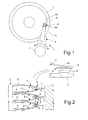
  • Figure 1 is a top plan view of a read/write assembly for magnetic hard disks;
  • Figure 2 is a longitudinally sectioned side view of the read/write assembly of Figure 1;
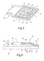
  • Figure 3 is a simplified view of a detail of the assembly of Figure 1, implementing a first embodiment of the present invention;
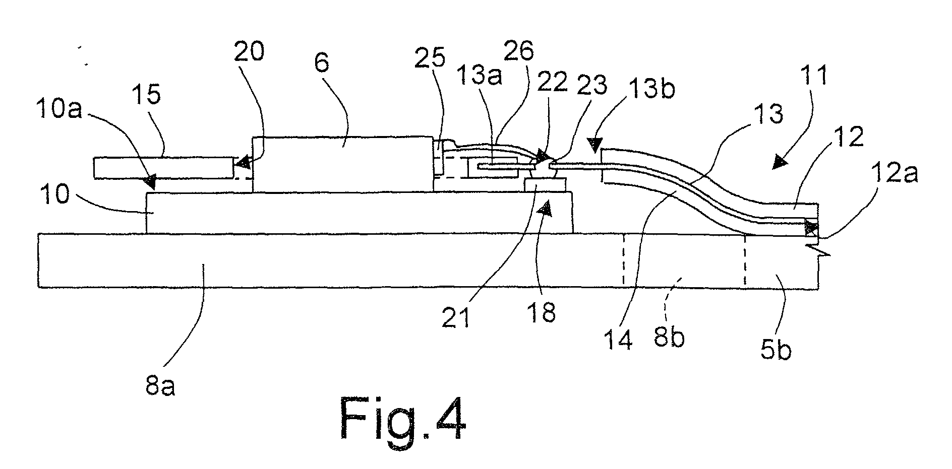
  • Figure 4 is a longitudinally sectioned side view of the detail of Figure 3;
  • Figure 5 is a top plan view of the detail of Figure 3;
  • Figure 6 is a longitudinally sectioned side view of a detail of the read/write assembly implementing a second embodiment of the present invention;
  • Figures 7 and 8 are top plan views of the detail of Figure 6, respectively, in an assembly step and in use; and
  • Figure 9 is a longitudinally sectioned side view of a detail of a read/write assembly implementing a third embodiment of the present invention.
With reference to Figures 1 to 3, number 1 designates a read/write assembly with dual-actuation stage for a hard disk. The assembly 1 is of a rotary type and comprises a motor 2 (also called "voice-coil motor") fixed to a supporting body 3, generally referred to as "E-block", owing to the fact that, in side view, it is E-shaped (see Figure 2). The supporting body 3 has a plurality of arms 4, each bearing a suspension 5 formed by a cantilevered fixed thin plate . Each suspension 5 carries, at its end that is not fixed to the supporting body 3, a read/write (R/W) transducer 6, which is set (in an operative condition) facing one surface of a hard disk 7 and is able to perform rolling and pitching movements in order to follow the surface of the hard disk 7. For this purpose the R/W transducer 6 (also referred to as "slider") is fixed to a joint (also referred to as "gimbal" or "flexure") 8, generally formed by the suspension 5 itself and constituted by, for example, a rectangular chip 8a, which is cut out on three and a half sides, starting from the lamina of the suspension 5, and the portion 8b of which for connection to the suspension 5 enables bending of the chip 8a under the weight of the slider 6 (see Figure 2). A micro-actuator 10 is set between the gimbal 8 and the slider 6, as may be seen in Figure 3, which shows the end of the suspension 5, the gimbal 8, the slider 6 and the micro-actuator 10, which in this case is of a rotary type. Figure 3 also shows a portion of a structure 11 for electrical connection, the said structure being carried by the suspension 5 and connecting the R/W transducer 6 and the micro-actuator 10 to a remote control device (known and not illustrated herein).
With reference to Figures 4 and 5, the structure 11 for electrical connection comprises a supporting film 12 made of polymeric material, a plurality of conductive paths 13 made on a surface 12a of the film 12 facing the suspension 5, and a passivation layer 14 coating the conductive paths 13. In addition, a protective structure 15 set for covering the micro-actuator 10, is made of a single piece with the structure 11 for electrical connection, in particular, as an extension of the film 12 towards the chip 8a, and incorporates ends 13a of the conductive paths 13. In greater detail, the film 12 and the conductive paths 13 of the electrical-connection structure 11 develop along an arm 5a and edges 5b of the suspension 5, from which the chip 8a has been cut out (see Figure 3). The conductive paths 13 are prolonged inside a connection portion 17 of the electrical-connection structure 11 that is set above the connection portion 8b which joins the chip 8a to the suspension 5. The protective structure 15 is made at one end of the connection portion 17, is anchored to an anchorage and connection region 18 of the micro-actuator 10, as explained later, and extends substantially parallel to a free face 10a of the micro-actuator 10, at a distance. The protective structure 15 is, in practice, a rectangular-shaped thin plate of , placed over the free face 10a of the micro-actuator 10. In addition, the protective structure 15 has, in a central position, an opening 20, through which the R/W transducer 6 is placed. In this way, the protective structure 15 prevents any penetration of dust or any other particles into the micro-actuator 10, but does not hinder movement of the micro-actuator 10 itself, and consequently enables fine positioning of the R/W transducer 6 during the tracking stage.
In an area corresponding to the region of anchorage and connection 18 of the micro-actuator 10, which comprises a plurality of control pads 21 made of conductive material, the protective structure 15 has a connection window 24 uncovering respective sections 13b for anchorage of the conductive paths 13, the said sections being locally without film 12 and without the passivation layer 14. Furthermore, in the uncovered anchorage sections 13b there are made respective holes 22. The anchorage sections 13b of the conductive paths 13 to be connected to the micro-actuator 10 are bonded to respective control pads 21 by local deposition of drops 23 of bonding material, which pass through respective holes 22 (according to the technique known as "zero-force bonding"). Alternatively, bonding may be carried out using the well-known techniques of ball bonding or stitch bonding.
According to the embodiment of the invention described herein, some of the conductive paths 13 are directly connected to respective read/write pads 25 of the R/W transducer 6 by means of wire connection lines 26 (wire-bonding technique). Alternatively, it is possible to provide read/write connections integrated in the micro-actuator 10: in this case, the read/write pads 25 are made on the micro-actuator 10 in the proximity of the control pads 21, and the connection to the respective conductive pads 13 is made applying the techniques referred to above (zero-force bonding, ball bonding or stitch bonding).
From what has been presented above, the advantages of the invention emerge clearly. In the first place, the protective structure 15 is made in an extremely simple way and is altogether separate from the micro-actuator 10. In particular, fabrication of the protective structure 15 does not involve additional fabrication steps, in so far as the said structure can be obtained simply by modifying the shape of the electrical-connection structure 11. Also the micro-actuator 10, which does not incorporate the protective structure 15, can be simplified. On the one hand, then, in order to fabricate the micro-actuator 10, a smaller number of fabrication steps and less complex steps are required; on the other hand, the overall dimensions of the micro-actuator 10 can be advantageously reduced.
Furthermore, the invention enables elimination of wire bonding between the electrical-connection structure 11 and the micro-actuator 10 and, possibly, also between the electrical-connection structure 11 and the R/W transducer 6. In this way, it is possible to build more compact assemblies and, in addition, the connection by means of direct bonding of the paths 13 is sturdier and more reliable than wire bonding.
A second embodiment of the invention will now be described hereinafter, with reference to Figures 6-8, in which parts that are the same as the ones already illustrated are designated by the same reference numbers. In particular, in addition to the motor 2 and to the supporting body 3 of Figure 1, a read/write assembly 30 comprises the suspension 5, the gimbal 8, the R/W transducer 6, the micro-actuator 10, an electrical-connection structure 31, carried by the suspension 5, and a protective structure 32, which is made of a single piece with the electrical-connection structure 31. In this case, the electrical-connection structure 31 comprises a supporting film 33 and a plurality of conductive paths 34 made on one face 33a of the film 33 opposite to the suspension 5. In addition, the protective structure 32 is formed by the film 33 and extends in a direction opposite to the chip 8a (see Figure 7). In greater detail, the protective structure 32 is made at one end of a connection portion 35 and, during a step of bonding to the suspension 5, is projected longitudinally outwards in the same plane as the electrical-connection structure 31 (see Figure 7). In use, the connection portion 35 is folded back in hinge-like fashion substantially through 180°, so that the protective structure 32 is set on top of the micro-actuator 10 (see Figures 7 and 8). Also in this case, the R/W transducer 6 is placed through a circular opening 36, made in the centre of the protective structure 32. Furthermore, the connection between the electrical-connection structure 31, on the one hand, and the R/W transducer 6 and the micro-actuator 10, on the other hand, is made as explained above, with reference to Figures 4 and 5. In this case, in particular, uncovered sections 34a of the connection paths 34 are alternatively bonded to respective control pads 21 of the micro-actuator 10 or connected to read/write pads of the R/W transducer 6 by wire bonding.
According to a further embodiment of the invention, illustrated in Figure 9, a read/write assembly 40 comprises, in addition to the motor 2 and the supporting body 3 of Figure 1, the suspension 5, the gimbal 8, the R/W transducer 6, the micro-actuator 10, an electrical-connection structure 41 carried by the suspension 5, and a protective structure 42 made of a single piece with the electrical-connection structure 41. The electrical-connection structure 41 comprises a supporting film 43 and is provided with control conductive paths 44 made on a first face 43a of the film 43 facing the suspension 5, and read/write conductive paths 45 made on a second face 43b of the film 43 opposite the first face 43a. In addition, the protective structure 42, which is made of a single piece with the electrical-connection structure 41 and is provided with an opening 50, is placed so as to cover the micro-actuator 10, so that the R/W transducer 6 is inserted through the opening 50. In this case, ends 44a, 45a, respectively of the control conductive paths 44 and of the read/write conductive paths 45 are free for a predetermined length and are, moreover, suspended. In greater detail, the ends 44a of the control conductive paths are bonded to respective control pads 21 of the micro-actuator 10 by means of bonding layers 46; the ends 45a of the read/write conductive paths 45 are, instead, bonded to respective read/write pads 25 of the R/W transducer 6. In this case, in particular, drops 48 of bonding material are used.
The solution described above enables a particularly flexible connection with the R/W transducer 6. Furthermore, given that the conductive paths are located on distinct planes and in pairs on top of one another, the overall dimensions of the electrical connection 41 are considerably reduced.
Finally, it is clear that numerous modifications and variations may be made to the read/write assembly for magnetic hard disks described and illustrated herein, all of which fall within the scope of the inventive idea, as defined in the attached claims.
Claims (14)

  1. A read/write assembly for magnetic hard disks comprising:
    a supporting element (5, 8);
    a read/write (R/W) transducer (6);
    a micro-actuator (10), set between said R/W transducer (6) and said supporting element (5, 8);
    an electrical-connection structure (11; 31; 41) for connection with a remote device, carried by said supporting element (5, 8) and connected to said R/W transducer (6) and to said micro-actuator (10); and
    a protective structure (15; 32; 42), set so as to cover said micro-actuator (10);
    characterized in that said protective structure (15; 32; 42) is made of a single piece with said electrical-connection structure (11; 31; 41).
  2. The assembly according to Claim 1, characterized in that said protective structure (15; 32; 42) has centrally an opening (20; 36; 50), said R/W transducer (6) being placed through said opening (20; 36; 50).
  3. The assembly according to Claim 1 or Claim 2, characterized in that said protective structure (12; 32; 42) extends substantially parallel to a face (10a) of said micro-actuator (10).
  4. The assembly according to any one of the preceding claims, characterized in that said electrical-connection structure (11; 31; 41) comprises a film (12; 33; 43) of dielectric material and a plurality of conductive paths (13; 34; 44, 45) provided on said film (12; 33; 43) and in that said protective structure (15; 32; 42) is a thin plate extending as a single piece from said film (12; 33; 43).
  5. The assembly according to Claim 4, characterized in that said micro-actuator comprises a region of anchorage and connection (18) and in that said protective structure (15; 32; 42) is bonded to said anchorage and connection region (18).
  6. The assembly according to Claim 5, characterized in that said anchorage and connection region (18) comprises a plurality of control pads (21), said conductive paths (13; 34; 44) being bonded to respective control pads (21).
  7. The assembly according to Claim 6, characterized in that said conductive paths have respective uncovered sections (13b; 34b) in areas corresponding to said control pads (21).
  8. The assembly according to any of Claims 4 to 7, characterized in that said protective structure (15; 32; 42) incorporates ends (13a; 34a) of said conductive paths (13; 34).
  9. The assembly according to any of Claims 4 to 8, characterized in that said conductive paths (13) are made on a face (12a) of said film (12) facing said supporting element (5, 8).
  10. The assembly according to any of Claims 4 to 8, characterized in that said protective structure (32) is made at one end of a connection portion (35) of said electrical-connection structure (31), which projects longitudinally outwards and is folded back in hinge-like fashion through substantially 180°.
  11. The assembly according to Claim 10, characterized in that said conductive paths (34) are made on one face (33a) of said film (33) opposite to said supporting element (5, 8).
  12. The assembly according to Claim 6, characterized in that said conductive paths comprise control conductive paths (44) made on a first face (43a) of said film (43) facing said supporting element (5), and read/write conductive paths (45) made on a second face (43b) of said film (43) opposite to said first face (43a).
  13. The assembly according to Claim 12, characterized in that respective ends (44a; 45a) respectively of said control conductive paths (44) and of said read/write conductive paths (45) are free for a pre-set length and are moreover suspended.
  14. The assembly according to Claim 13, characterized in that said ends (44a) of said control conductive paths (44) are bonded to respective said control pads (21), and said ends (45a) of said read/write conductive paths (45) are bonded to read/write pads (25) of said R/W transducer (6).
EP02425276A 2002-05-03 2002-05-03 Read/write assembly for magnetic hard disks Withdrawn EP1359569A1 (en)

Priority Applications (2)

Application Number Priority Date Filing Date Title
EP02425276A EP1359569A1 (en) 2002-05-03 2002-05-03 Read/write assembly for magnetic hard disks
US10/429,266 US7116525B2 (en) 2002-05-03 2003-05-02 Read/write assembly for magnetic hard disks

Applications Claiming Priority (1)

Application Number Priority Date Filing Date Title
EP02425276A EP1359569A1 (en) 2002-05-03 2002-05-03 Read/write assembly for magnetic hard disks

Publications (1)

Publication Number Publication Date
EP1359569A1 true EP1359569A1 (en) 2003-11-05

Family

ID=28799775

Family Applications (1)

Application Number Title Priority Date Filing Date
EP02425276A Withdrawn EP1359569A1 (en) 2002-05-03 2002-05-03 Read/write assembly for magnetic hard disks

Country Status (2)

Country Link
US (1) US7116525B2 (en)
EP (1) EP1359569A1 (en)

Families Citing this family (2)

* Cited by examiner, † Cited by third party
Publication number Priority date Publication date Assignee Title
EP1312580B1 (en) * 2001-11-16 2007-01-24 STMicroelectronics S.r.l. Process for sealing devices incorporating microstructures
US8085508B2 (en) 2008-03-28 2011-12-27 Hitachi Global Storage Technologies Netherlands B.V. System, method and apparatus for flexure-integrated microactuator

Citations (1)

* Cited by examiner, † Cited by third party
Publication number Priority date Publication date Assignee Title
EP0977180A1 (en) * 1998-07-30 2000-02-02 STMicroelectronics S.r.l. Method for assembling an actuator device for a hard disc, comprising a read/write transducer, a microactuator and a suspension and actuator device thus obtained

Family Cites Families (5)

* Cited by examiner, † Cited by third party
Publication number Priority date Publication date Assignee Title
US3789378A (en) * 1971-05-24 1974-01-29 Olivetti & Co Spa Transducer positioning mechanism
EP0556436B1 (en) * 1992-02-19 2001-09-05 Tandberg Data Asa Method and apparatus for positioning of a magnetic head
US5521778A (en) * 1994-08-30 1996-05-28 International Business Machines Corporation Disk drive with primary and secondary actuator drives
US5657188A (en) * 1995-06-01 1997-08-12 Hutchinson Technology Incorporated Head suspension with tracking microactuator
JP3653602B2 (en) 1996-10-31 2005-06-02 株式会社日立製作所 Magnetic disk unit

Patent Citations (1)

* Cited by examiner, † Cited by third party
Publication number Priority date Publication date Assignee Title
EP0977180A1 (en) * 1998-07-30 2000-02-02 STMicroelectronics S.r.l. Method for assembling an actuator device for a hard disc, comprising a read/write transducer, a microactuator and a suspension and actuator device thus obtained

Also Published As

Publication number Publication date
US20030235013A1 (en) 2003-12-25
US7116525B2 (en) 2006-10-03

Similar Documents

Publication Publication Date Title
US7525769B2 (en) Micro-actuator having swing support to allow horizontal swinging movement of slider support
US6351354B1 (en) Head to flexure interconnection for disc drive microactuator
US9390739B1 (en) Piezoelectric microactuator with restraining layer for control of bending
US20210272592A1 (en) Multi-Layer PZT Microactuator Having A Poled But Inactive PZT Constraining Layer
US10074390B1 (en) Multi-layer PZT microactuator with active PZT constraining layer for a DSA suspension
US9330699B1 (en) Piezoelectric actuator with wrap-around electrode on inactive constraining layer
US6501623B1 (en) Method for assembling an actuator device for a hard disk, comprising a read/write transducer, a microactuator, and a suspension, and the actuator device thus obtained
US11694716B2 (en) Multi-layer PZT microactuator with active PZT constraining layers for a DSA suspension
US9330696B1 (en) DSA suspension having PZT with overhanging constraint layer and electrical connection thereto
JP7402264B2 (en) Multilayer PZT microactuator with a PZT suppression layer that is polarized but inactive
US20220199114A1 (en) Multi-Layer PZT Microactuator with Active PZT Constraining Layers for a DSA Suspension
US6831539B1 (en) Magnetic microactuator for disc with integrated head connections and limiters drives
US6757135B2 (en) Leading edge bond pads
US6507463B1 (en) Micro disc drive employing arm level microactuator
EP1359569A1 (en) Read/write assembly for magnetic hard disks
JP2000243051A (en) Hard disk reading/writing unit and manufacture thereof
US7987582B2 (en) Method of manufacturing a head gimbal assembly
JP3515503B2 (en) Method of manufacturing a floating member for electrically connecting two movable parts of a micromechanism with respect to each other
US6504685B1 (en) Microelectricalmechanical device immobilization and sealing
CN115699176B (en) Multilayer PZT microactuator with active PZT constraining layer for DSA suspension
JP2007149330A (en) Head gimbal assembly and disk drive unit including the head gimbal assembly
JP2001077300A (en) Method of assembling a group comprising at least one first element and one second element, and a unit so assembled

Legal Events

Date Code Title Description
PUAI Public reference made under article 153(3) epc to a published international application that has entered the european phase

Free format text: ORIGINAL CODE: 0009012

AK Designated contracting states

Kind code of ref document: A1

Designated state(s): AT BE CH CY DE DK ES FI FR GB GR IE IT LI LU MC NL PT SE TR

AX Request for extension of the european patent

Extension state: AL LT LV MK RO SI

17P Request for examination filed

Effective date: 20040503

AKX Designation fees paid

Designated state(s): DE FR GB IT

GRAP Despatch of communication of intention to grant a patent

Free format text: ORIGINAL CODE: EPIDOSNIGR1

GRAC Information related to communication of intention to grant a patent modified

Free format text: ORIGINAL CODE: EPIDOSCIGR1

GRAS Grant fee paid

Free format text: ORIGINAL CODE: EPIDOSNIGR3

STAA Information on the status of an ep patent application or granted ep patent

Free format text: STATUS: THE APPLICATION IS DEEMED TO BE WITHDRAWN

18D Application deemed to be withdrawn

Effective date: 20081202