EP1359448A2 - Loose tube optical ribbon cable - Google Patents
Loose tube optical ribbon cable Download PDFInfo
- Publication number
- EP1359448A2 EP1359448A2 EP02022299A EP02022299A EP1359448A2 EP 1359448 A2 EP1359448 A2 EP 1359448A2 EP 02022299 A EP02022299 A EP 02022299A EP 02022299 A EP02022299 A EP 02022299A EP 1359448 A2 EP1359448 A2 EP 1359448A2
- Authority
- EP
- European Patent Office
- Prior art keywords
- optical ribbon
- ribbon cable
- optical
- water absorbing
- tensile strength
- Prior art date
- Legal status (The legal status is an assumption and is not a legal conclusion. Google has not performed a legal analysis and makes no representation as to the accuracy of the status listed.)
- Granted
Links
Images


Classifications
-
- G—PHYSICS
- G02—OPTICS
- G02B—OPTICAL ELEMENTS, SYSTEMS OR APPARATUS
- G02B6/00—Light guides; Structural details of arrangements comprising light guides and other optical elements, e.g. couplings
- G02B6/44—Mechanical structures for providing tensile strength and external protection for fibres, e.g. optical transmission cables
- G02B6/4401—Optical cables
- G02B6/441—Optical cables built up from sub-bundles
- G02B6/4411—Matrix structure
-
- G—PHYSICS
- G02—OPTICS
- G02B—OPTICAL ELEMENTS, SYSTEMS OR APPARATUS
- G02B6/00—Light guides; Structural details of arrangements comprising light guides and other optical elements, e.g. couplings
- G02B6/44—Mechanical structures for providing tensile strength and external protection for fibres, e.g. optical transmission cables
- G02B6/4401—Optical cables
- G02B6/4429—Means specially adapted for strengthening or protecting the cables
- G02B6/44384—Means specially adapted for strengthening or protecting the cables the means comprising water blocking or hydrophobic materials
-
- G—PHYSICS
- G02—OPTICS
- G02B—OPTICAL ELEMENTS, SYSTEMS OR APPARATUS
- G02B6/00—Light guides; Structural details of arrangements comprising light guides and other optical elements, e.g. couplings
- G02B6/44—Mechanical structures for providing tensile strength and external protection for fibres, e.g. optical transmission cables
- G02B6/4401—Optical cables
- G02B6/4429—Means specially adapted for strengthening or protecting the cables
- G02B6/4434—Central member to take up tensile loads
Definitions
- the present invention relates to an optical ribbon cable, and more particularly to an optical ribbon cable with loose tubes.
- optical ribbon cables typically include optical ribbon fibers as a transmission medium for optical signals.
- Optical ribbon fibers are made of multiple cores of the optical fibers stranded in a single row and can be fabricated by stranding the multiple cores of the optical fibers in a single row, then sheathing them with UV curable resin, followed by curing the UV curable resin with UV.
- multiple optical ribbon fibers can be laminated to compose a bundle of optical ribbon fibers with a matrix structure. This type of optical ribbon fibers have an advantage in that fiber density is very high in a limited space as multiple optical fibers are closely packed. As such, many attentions are given to the use of high-density optical ribbon cables.
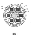
- Fig. 1 is a cross-sectional view illustrating a configuration of a conventional loose tube optical ribbon cable.
- the optical ribbon cable comprises a central tensile strength component 110, a number of bundle optical ribbon fibers 120, a plurality of loose tubes 130, a tensile strength component 140, and an external sheath 150.
- the central tensile strength component 110 provides tensile strength for the loose tube optical ribbon cable, thus situated in the center thereof.
- the loose tubes 130 are mounted with a bundle of optical ribbon fibers 120.
- the bundle of optical ribbon fibers 120 has a matrix structure, where 4 or more cores of optical fibers are stranded in a single row and sheathed with UV curable resin to form an optical ribbon fiber, followed by lamination of multiple optical ribbon fibers.
- the tensile strength component 140 surrounds the plurality of loose tubes 130 and performs a function of improving the tensile strength of the loose tube optical ribbon cable.
- the external sheath 150 is formed using an extrusion process. The sheath comprises the outermost layer of the optical ribbon cable so as to protect its interior against the external environment.
- the present invention overcomes the above-described problems, and provides additional advantages, by providing a loose tube optical ribbon cable, having improved water resistance and compression properties as well as exhibiting a good appearance.
- the loose tube, optical-ribbon cable includes a central tensile strength component situated in the center of the optical ribbon cable; a plurality of loose tubes mounted with a bundle of optical ribbon fibers, the bundle of optical ribbon fibers being formed by laminating multiple optical ribbon fibers, each optical ribbon fiber including multiple cores of optical fibers stranded in a single row and a sheath surrounding the multiple cores of optical fibers, the plurality of loose tubes being stranded around the central tensile strength component; a plurality of circle-shaped water absorbing members arranged in a hollow which is formed outside a pair of the loose tubes neighboring each other; a water absorbing tape for surrounding the plurality of loose tubes and the plurality of circle-shaped water absorbing members; and, an external sheath situated outermost of the optical ribbon cable for protecting the interior of the loose tube optical ribbon cable against the external environment.
- Fig. 2 is a cross-sectional view illustrating the configuration of a loose tube, optical ribbon cable in accordance with a preferred embodiment of the present invention.
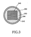
- Fig. 3 is a cross-sectional view illustrating the loose tube illustrated in Fig. 2.
- Fig. 4 a cross-sectional view illustrating the circle-shaped, water-absorbing member illustrated in Fig. 2.
- the optical ribbon cable comprises a central tensile strength component 210, a plurality of loose tubes 260, a plurality of circle-shaped, water absorbing members 300, a second water absorbing tape 270, a tensile strength component 280, and an external sheath 290.
- the central tensile strength component 210 provides tensile strength for the loose tube, optical ribbon cable and situated in the center thereof.
- fiberglass reinforced plastic (FRP) is available.
- FRP fiberglass reinforced plastic
- a polymer compound such as polyvinyl chloride (PVC), polyethylene (PE), etc. is available.
- PVC polyvinyl chloride
- PE polyethylene
- the coated central tensile strength component 210 and 220 is wound with a first water absorbing tape 230.
- the first water absorbing tape 230 performs the function of absorbing moisture residing between the central tensile strength component 210 and the plurality of loose tubes 260.
- the loose tubes 260 are mounted with a bundle of optical ribbon fibers 240.
- the bundle of optical ribbon fibers 240 has a matrix structure, where 4 or more cores of optical fibers 242 are stranded in a single row and sheathed with UV curable resin to form an optical ribbon fiber, followed by lamination of multiple optical ribbon fibers.
- a jelly compound 250 is packed in an empty space of the loose tubes 260 so as to protect the bundles of optical ribbon fibers 240 from external impact and to perform the absorption of moisture penetrated into the loose tubes 260.
- the plurality of loose tubes 260 may be stranded around the central tensile strength component 210, in a helical or S-Z pattern.
- the circle-shaped, water-absorbing members 300 are arranged in a hollow formed outside a pair of neighboring loose tubes 260 and are water resistant. For these reasons, the water absorbing members 300 absorb moisture residing between the second water absorbing tape 270 and the plurality of loose tubes 260.
- the circle-shaped, water-absorbing members 300 have a certain degree of strength so that they improve compressibility of the optical ribbon cable. Further, the circle-shaped, water absorbing members 300 fill the hollow formed by the plurality of loose tubes 260, thereby enabling a cross-section of the optical ribbon cable to be maintained in a circle shape.
- the circle-shaped, water absorbing members 300 may include multiple water absorbing yarns and strength yarns twisted together to form an overall circle.
- the circle-shaped, water-absorbing members 300 may include three cores of water absorbing yarns 310, each core absorbing moisture and being swelled, and four cores of strength yarns 320, each core having a certain degree of strength, thereby maintaining a shape of the circle-shaped water absorbing members.
- the three cores of water absorbing yarns 310 and four cores of strength yarns 320 are twisted together, so forming an overall circle.
- the strength yarns 320 aramid yarns or glass yarns are available.
- the second water absorbing tape 270 surrounds the plurality of loose tubes 260 and the plurality of circle-shaped, water absorbing member 300, thereby preventing the penetration of moisture into the interior thereof.
- the tensile strength component 280 surrounds the second, water absorbing tape 270, and performs a function of improving tensile strength of the optical ribbon cable.
- aramid yarns or glass yarns are available.
- the external sheath 290 is situated at the outermost surface of the loose tube optical ribbon cable.
- a polymer compound such as polyvinyl chloride (PVC), polyethylene (PE), hytrel, nylon, and polypropylene is available.
- the external sheath 290 is formed using an extrusion process.
- the external sheath 290 may be mounted with a rip cord (not illustrated) adjacent to the inside thereof for convenience upon removal thereof.
- the loose tube optical ribbon cable according to the present invention employs circle-shaped water absorbing members, so having advantages of improved water resistance and compression properties, and having an improved appearance.
Abstract
Description
- This application makes reference to and claims all benefits accruing under 35 U.S.C. Section 119 from an application entitled, "LOOSE TUBE OPTICAL RIBBON CABLE", filed in the Korean Industrial Property Office on April 30, 2002 and there duly assigned Serial No. 2002-23829.
- The present invention relates to an optical ribbon cable, and more particularly to an optical ribbon cable with loose tubes.
- Typically, optical ribbon cables include optical ribbon fibers as a transmission medium for optical signals. Optical ribbon fibers are made of multiple cores of the optical fibers stranded in a single row and can be fabricated by stranding the multiple cores of the optical fibers in a single row, then sheathing them with UV curable resin, followed by curing the UV curable resin with UV. In addition, multiple optical ribbon fibers can be laminated to compose a bundle of optical ribbon fibers with a matrix structure. This type of optical ribbon fibers have an advantage in that fiber density is very high in a limited space as multiple optical fibers are closely packed. As such, many attentions are given to the use of high-density optical ribbon cables. The reason is that a large number of optical cables have been already installed in existing duct lines, so there is a shortage of space for the installation of new cables. Moreover, in view of efforts to reduce the outer diameters of optical cables or any increase in the packing density of optical fibers, the installation of such cables is ideal in the existing narrow ducts.
- Fig. 1 is a cross-sectional view illustrating a configuration of a conventional loose tube optical ribbon cable. The optical ribbon cable comprises a central
tensile strength component 110, a number of bundleoptical ribbon fibers 120, a plurality ofloose tubes 130, atensile strength component 140, and anexternal sheath 150. - As shown in Fig. 1, the central
tensile strength component 110 provides tensile strength for the loose tube optical ribbon cable, thus situated in the center thereof. Theloose tubes 130 are mounted with a bundle ofoptical ribbon fibers 120. The bundle ofoptical ribbon fibers 120 has a matrix structure, where 4 or more cores of optical fibers are stranded in a single row and sheathed with UV curable resin to form an optical ribbon fiber, followed by lamination of multiple optical ribbon fibers. - The
tensile strength component 140 surrounds the plurality ofloose tubes 130 and performs a function of improving the tensile strength of the loose tube optical ribbon cable. Theexternal sheath 150 is formed using an extrusion process. The sheath comprises the outermost layer of the optical ribbon cable so as to protect its interior against the external environment. - However, the above-described conventional loose tube, optical ribbon cable have drawbacks in that it has a poor resistance to moisture penetration and external stresses (pressure force, impact, etc). In addition, in terms of a physical appearance of the loose tube optical ribbon cable, it is difficult to retain its original cross sectional form because a hollow 160 is formed outside the pair of neighboring
loose tubes 130. - Therefore, the present invention overcomes the above-described problems, and provides additional advantages, by providing a loose tube optical ribbon cable, having improved water resistance and compression properties as well as exhibiting a good appearance.
- In accordance with the present invention, the loose tube, optical-ribbon cable includes a central tensile strength component situated in the center of the optical ribbon cable; a plurality of loose tubes mounted with a bundle of optical ribbon fibers, the bundle of optical ribbon fibers being formed by laminating multiple optical ribbon fibers, each optical ribbon fiber including multiple cores of optical fibers stranded in a single row and a sheath surrounding the multiple cores of optical fibers, the plurality of loose tubes being stranded around the central tensile strength component; a plurality of circle-shaped water absorbing members arranged in a hollow which is formed outside a pair of the loose tubes neighboring each other; a water absorbing tape for surrounding the plurality of loose tubes and the plurality of circle-shaped water absorbing members; and, an external sheath situated outermost of the optical ribbon cable for protecting the interior of the loose tube optical ribbon cable against the external environment.
- The above features and other advantages of the present invention will be more clearly understood from the following detailed description taken in conjunction with the accompanying drawings, in which:
- Fig. 1 is a cross-sectional view illustrating a configuration of a conventional loose tube optical ribbon cable;
- Fig. 2 is a cross-sectional view illustrating a configuration of a loose tube optical ribbon cable in accordance with a preferred embodiment of the present invention;
- Fig. 3 is a cross-sectional view illustrating a loose tube illustrated in Fig. 2; and,
- Fig. 4 a cross-sectional view illustrating a circle-shaped, water absorbing member illustrated in Fig. 2.
-
- In the following description, for purposes of explanation rather than limitation, specific details are set forth such as the particular architecture, interfaces, techniques, etc., in order to provide a thorough understanding of the present invention. For purposes of simplicity and clarity, detailed descriptions of well-known devices, circuits, and methods are omitted so as not to obscure the description of the present invention with unnecessary detail.
- Fig. 2 is a cross-sectional view illustrating the configuration of a loose tube, optical ribbon cable in accordance with a preferred embodiment of the present invention. Fig. 3 is a cross-sectional view illustrating the loose tube illustrated in Fig. 2. Fig. 4 a cross-sectional view illustrating the circle-shaped, water-absorbing member illustrated in Fig. 2.
- As shown in Fig. 2, the optical ribbon cable comprises a central
tensile strength component 210, a plurality ofloose tubes 260, a plurality of circle-shaped,water absorbing members 300, a secondwater absorbing tape 270, atensile strength component 280, and anexternal sheath 290. - The central
tensile strength component 210 provides tensile strength for the loose tube, optical ribbon cable and situated in the center thereof. As a material for the centraltensile strength component 210, fiberglass reinforced plastic (FRP) is available. For a material of alayer 220 coated on the centraltensile strength component 210, a polymer compound such as polyvinyl chloride (PVC), polyethylene (PE), etc. is available. Further, the coated centraltensile strength component water absorbing tape 230. The firstwater absorbing tape 230 performs the function of absorbing moisture residing between the centraltensile strength component 210 and the plurality ofloose tubes 260. - The
loose tubes 260 are mounted with a bundle ofoptical ribbon fibers 240. The bundle ofoptical ribbon fibers 240 has a matrix structure, where 4 or more cores ofoptical fibers 242 are stranded in a single row and sheathed with UV curable resin to form an optical ribbon fiber, followed by lamination of multiple optical ribbon fibers. In addition, ajelly compound 250 is packed in an empty space of theloose tubes 260 so as to protect the bundles ofoptical ribbon fibers 240 from external impact and to perform the absorption of moisture penetrated into theloose tubes 260. The plurality ofloose tubes 260 may be stranded around the centraltensile strength component 210, in a helical or S-Z pattern. - The circle-shaped, water-absorbing
members 300 are arranged in a hollow formed outside a pair of neighboringloose tubes 260 and are water resistant. For these reasons, thewater absorbing members 300 absorb moisture residing between the secondwater absorbing tape 270 and the plurality ofloose tubes 260. The circle-shaped, water-absorbingmembers 300 have a certain degree of strength so that they improve compressibility of the optical ribbon cable. Further, the circle-shaped,water absorbing members 300 fill the hollow formed by the plurality ofloose tubes 260, thereby enabling a cross-section of the optical ribbon cable to be maintained in a circle shape. The circle-shaped,water absorbing members 300 may include multiple water absorbing yarns and strength yarns twisted together to form an overall circle. - Referring to Fig. 4, the circle-shaped, water-absorbing
members 300 may include three cores ofwater absorbing yarns 310, each core absorbing moisture and being swelled, and four cores ofstrength yarns 320, each core having a certain degree of strength, thereby maintaining a shape of the circle-shaped water absorbing members. The three cores ofwater absorbing yarns 310 and four cores ofstrength yarns 320 are twisted together, so forming an overall circle. As for thestrength yarns 320, aramid yarns or glass yarns are available. - With continued reference to Fig. 2, the second
water absorbing tape 270 surrounds the plurality ofloose tubes 260 and the plurality of circle-shaped,water absorbing member 300, thereby preventing the penetration of moisture into the interior thereof. Thetensile strength component 280 surrounds the second,water absorbing tape 270, and performs a function of improving tensile strength of the optical ribbon cable. As a material for the tensile strength component, aramid yarns or glass yarns are available. Theexternal sheath 290 is situated at the outermost surface of the loose tube optical ribbon cable. As a material for theexternal sheath 290, a polymer compound such as polyvinyl chloride (PVC), polyethylene (PE), hytrel, nylon, and polypropylene is available. Theexternal sheath 290 is formed using an extrusion process. In addition, theexternal sheath 290 may be mounted with a rip cord (not illustrated) adjacent to the inside thereof for convenience upon removal thereof. - As apparent from the above description, the loose tube optical ribbon cable according to the present invention employs circle-shaped water absorbing members, so having advantages of improved water resistance and compression properties, and having an improved appearance.
- Although the preferred embodiments of the present invention have been disclosed for illustrative purposes, those skilled in the art will appreciate that various modifications, additions and substitutions are possible, without departing from the scope and spirit of the invention as disclosed in the accompanying claims.
Claims (8)
- A loose tube, optical ribbon cable comprising:a central tensile strength component situated in the center of the optical ribbon cable;a plurality of loose tubes having a bundle of optical ribbon fibers surrounding the central tensile strength component and disposed in parallel arrangement, one to each other, the bundle of optical ribbon fibers being formed by laminating the optical ribbon fibers, each optical ribbon fiber including multiple cores of optical fibers stranded in a single row and a sheath surrounding the multiple cores of optical fibers;a plurality of circle-shaped, water absorbing members disposed between the plurality of tubes;a water absorbing tape for surrounding the plurality of loose tubes and the plurality of circle-shaped, water absorbing members; and,an external sheath forming an outermost layer of the optical ribbon cable, for protecting an interior of the loose tube, optical ribbon cable against an external environment.
- The loose tube, optical ribbon cable as set forth in claim 1, wherein the circle-shaped, water absorbing members include:wherein the plurality of water absorbing yarns and the plurality of strength yarns being twisted together to maintain a shape of the circle-shaped, water absorbing members.a plurality of water absorbing yarns, each yarn having a moisture absorption property; anda plurality of strength yarns, each yarn having a certain degree of strength,
- The loose tube, optical ribbon cable as set forth in claim 1, further comprising a tensile strength component situated between the water absorbing tape and the external sheath to enhance tensile strength thereof.
- The loose tube, optical ribbon cable as set forth in claim 2, further comprising a tensile strength component situated between the water absorbing tape and the external sheath to enhance tensile strength thereof.
- The loose tube, optical ribbon cable as set forth in claim 1, wherein the central tensile strength component is defined by fiberglass reinforced plastic (FRP) material.
- The loose tube, optical ribbon cable as set forth in claim 1, wherein an outer layer of the central tensile strength component is defined by a polymer, polyvinyl chloride (PVC), and polyethylene (PE) compound.
- The loose tube, optical ribbon cable as set forth in claim 1, wherein the external sheath is defined by a polymer, polyvinyl chloride (PVC), polyethylene (PE), hytrel, nylon, and polypropylene material.
- The loose tube, optical ribbon cable as set forth in claim 1, wherein the external sheath is formed using an extrusion technique.
Applications Claiming Priority (2)
| Application Number | Priority Date | Filing Date | Title |
|---|---|---|---|
| KR2382092002 | 2002-04-30 | ||
| KR10-2002-0023829A KR100442687B1 (en) | 2002-04-30 | 2002-04-30 | Loose tube optical ribbon cable |
Publications (3)
| Publication Number | Publication Date |
|---|---|
| EP1359448A2 true EP1359448A2 (en) | 2003-11-05 |
| EP1359448A3 EP1359448A3 (en) | 2004-07-14 |
| EP1359448B1 EP1359448B1 (en) | 2007-07-25 |
Family
ID=29244815
Family Applications (1)
| Application Number | Title | Priority Date | Filing Date |
|---|---|---|---|
| EP02022299A Expired - Fee Related EP1359448B1 (en) | 2002-04-30 | 2002-10-07 | Loose tube optical ribbon cable |
Country Status (6)
| Country | Link |
|---|---|
| US (1) | US6751383B2 (en) |
| EP (1) | EP1359448B1 (en) |
| JP (1) | JP3920240B2 (en) |
| KR (1) | KR100442687B1 (en) |
| CN (1) | CN1212532C (en) |
| DE (1) | DE60221356D1 (en) |
Cited By (1)
| Publication number | Priority date | Publication date | Assignee | Title |
|---|---|---|---|---|
| CN113640932A (en) * | 2021-09-02 | 2021-11-12 | 江苏长飞中利光纤光缆有限公司 | Central beam tube type optical cable and central beam tube type ribbon optical cable |
Families Citing this family (17)
| Publication number | Priority date | Publication date | Assignee | Title |
|---|---|---|---|---|
| KR100474726B1 (en) * | 2002-11-07 | 2005-03-11 | 삼성전자주식회사 | Optical fiber cable for access network |
| KR100617745B1 (en) * | 2004-05-31 | 2006-08-28 | 삼성전자주식회사 | Optical fiber cable |
| DE102004037589A1 (en) * | 2004-08-03 | 2006-03-16 | CCS Technology, Inc., Wilmington | Optical cable and method of making an optical cable |
| US7298946B2 (en) * | 2004-12-22 | 2007-11-20 | Hewlett-Packard Development Company, L.P. | Multi-fiber cable for efficient manageability of optical system |
| US7221831B2 (en) * | 2005-03-03 | 2007-05-22 | Nexans | Multi-tube fiber optic cable and system and method for making the same |
| US8737788B2 (en) * | 2007-11-01 | 2014-05-27 | Nexans | Fiber optic cable design with improved compression test results |
| JP5347989B2 (en) | 2010-01-21 | 2013-11-20 | 住友電気工業株式会社 | Multi-core optical fiber |
| US8639076B2 (en) | 2010-08-17 | 2014-01-28 | Nexans | Fiber optic cable with improved low temperature and compression resistance |
| KR101351456B1 (en) * | 2012-04-05 | 2014-01-14 | 엘에스전선 주식회사 | Multi-core optical cable for air blown installation |
| EP2845043A4 (en) | 2012-05-02 | 2015-12-16 | Fujikura Ltd | Round and small diameter optical cables with a ribbon-like optical fiber structure |
| KR102440833B1 (en) * | 2015-01-28 | 2022-09-05 | 엘에스전선 주식회사 | Ribbon-Tube Type Optical Cable |
| WO2018128230A1 (en) * | 2017-01-03 | 2018-07-12 | 엘에스전선 주식회사 | Anti-rodent optical cable |
| US11262516B2 (en) * | 2018-07-05 | 2022-03-01 | Prysmian S.P.A. | High density optical cables |
| US11156792B2 (en) * | 2019-10-01 | 2021-10-26 | Sterlite Technologies Limited | Loose tube cable with embedded strength member |
| CN211479726U (en) * | 2020-04-07 | 2020-09-11 | 菲时特集团股份有限公司 | Protection connecting pipe with corrosion resistance |
| US11747582B2 (en) * | 2021-12-20 | 2023-09-05 | Taihan Fiberoptics Co., Ltd. | Optical cable including rollable optical fiber ribbon |
| CN115047576B (en) * | 2022-08-15 | 2022-11-29 | 长飞光纤光缆股份有限公司 | Full-dry type sleeve unit adopting water-blocking powder and optical cable |
Citations (6)
| Publication number | Priority date | Publication date | Assignee | Title |
|---|---|---|---|---|
| EP0564130A1 (en) * | 1992-04-02 | 1993-10-06 | Pirelli Cable Corporation | Optical fiber cable with large number of ribbon units containing optical fibers and enclosed in tubes |
| US5621841A (en) * | 1995-09-20 | 1997-04-15 | Siecor Corporation | Optical fiber cable containing ribbons in stranded tubes |
| EP0777141A1 (en) * | 1995-11-30 | 1997-06-04 | AT&T Corp. | Loose tube fiber optic cable |
| US5642452A (en) * | 1995-02-21 | 1997-06-24 | Sumitomo Electric Lightwave Corp. | Water-blocked optical fiber communications cable |
| US6253012B1 (en) * | 1998-11-12 | 2001-06-26 | Alcatel | Cycled fiber lock for cross-functional totally dry optical fiber loose tube cable |
| US6304701B1 (en) * | 1998-03-27 | 2001-10-16 | Corning Cable Systems Llc | Dry fiber optic cable |
Family Cites Families (11)
| Publication number | Priority date | Publication date | Assignee | Title |
|---|---|---|---|---|
| JPH06100701B2 (en) * | 1987-03-30 | 1994-12-12 | 住友電気工業株式会社 | Water-stop tape for slotted optical fiber cables |
| US5389442A (en) * | 1988-07-11 | 1995-02-14 | At&T Corp. | Water blocking strength members |
| US5133034A (en) * | 1991-08-20 | 1992-07-21 | At&T Bell Laboratories | Communications cable having a strength member system disposed between two layers of waterblocking material |
| JPH05203852A (en) * | 1992-01-24 | 1993-08-13 | Showa Electric Wire & Cable Co Ltd | Water proof type optical fiber cable |
| JPH08122592A (en) * | 1994-10-24 | 1996-05-17 | Fujikura Ltd | Optical cable |
| JPH08220391A (en) * | 1995-02-08 | 1996-08-30 | Fujikura Ltd | Optical fiber cable |
| US5848212A (en) * | 1996-09-10 | 1998-12-08 | Siecor Corporation | High density optical cable |
| US6088499A (en) * | 1997-09-30 | 2000-07-11 | Siecor Corporation | Fiber optic cable with ripcord |
| US6185351B1 (en) * | 1999-10-15 | 2001-02-06 | Lucent Technologies, Inc. | All-dielectric, self-supporting, loose-tube cable with optical fiber ribbons |
| KR20010059913A (en) * | 1999-12-30 | 2001-07-06 | 김진찬 | Optical cable for waterless |
| KR100420174B1 (en) * | 2001-04-26 | 2004-03-02 | 엘지전선 주식회사 | Optical fiber cable containing ribbon units |
-
2002
- 2002-04-30 KR KR10-2002-0023829A patent/KR100442687B1/en not_active IP Right Cessation
- 2002-09-05 US US10/235,164 patent/US6751383B2/en not_active Expired - Lifetime
- 2002-10-07 DE DE60221356T patent/DE60221356D1/en not_active Expired - Lifetime
- 2002-10-07 EP EP02022299A patent/EP1359448B1/en not_active Expired - Fee Related
- 2002-10-08 CN CNB021457328A patent/CN1212532C/en not_active Expired - Fee Related
-
2003
- 2003-04-15 JP JP2003110142A patent/JP3920240B2/en not_active Expired - Fee Related
Patent Citations (6)
| Publication number | Priority date | Publication date | Assignee | Title |
|---|---|---|---|---|
| EP0564130A1 (en) * | 1992-04-02 | 1993-10-06 | Pirelli Cable Corporation | Optical fiber cable with large number of ribbon units containing optical fibers and enclosed in tubes |
| US5642452A (en) * | 1995-02-21 | 1997-06-24 | Sumitomo Electric Lightwave Corp. | Water-blocked optical fiber communications cable |
| US5621841A (en) * | 1995-09-20 | 1997-04-15 | Siecor Corporation | Optical fiber cable containing ribbons in stranded tubes |
| EP0777141A1 (en) * | 1995-11-30 | 1997-06-04 | AT&T Corp. | Loose tube fiber optic cable |
| US6304701B1 (en) * | 1998-03-27 | 2001-10-16 | Corning Cable Systems Llc | Dry fiber optic cable |
| US6253012B1 (en) * | 1998-11-12 | 2001-06-26 | Alcatel | Cycled fiber lock for cross-functional totally dry optical fiber loose tube cable |
Non-Patent Citations (1)
| Title |
|---|
| BONICEL J P ET AL: "OPTICAL CABLES FOR BROADBAND COMMUNICATION" ALCATEL TELECOMMUNICATIONS REVIEW, ALCATEL, PARIS CEDEX, FR, 1998, XP007005279 ISSN: 1267-7167 * |
Cited By (2)
| Publication number | Priority date | Publication date | Assignee | Title |
|---|---|---|---|---|
| CN113640932A (en) * | 2021-09-02 | 2021-11-12 | 江苏长飞中利光纤光缆有限公司 | Central beam tube type optical cable and central beam tube type ribbon optical cable |
| CN113640932B (en) * | 2021-09-02 | 2023-02-03 | 长飞光电线缆(苏州)有限公司 | Central beam tube type optical cable and central beam tube type ribbon optical cable |
Also Published As
| Publication number | Publication date |
|---|---|
| CN1455279A (en) | 2003-11-12 |
| CN1212532C (en) | 2005-07-27 |
| JP3920240B2 (en) | 2007-05-30 |
| KR20030085415A (en) | 2003-11-05 |
| EP1359448B1 (en) | 2007-07-25 |
| DE60221356D1 (en) | 2007-09-06 |
| KR100442687B1 (en) | 2004-08-02 |
| EP1359448A3 (en) | 2004-07-14 |
| JP2003322780A (en) | 2003-11-14 |
| US6751383B2 (en) | 2004-06-15 |
| US20030202757A1 (en) | 2003-10-30 |
Similar Documents
| Publication | Publication Date | Title |
|---|---|---|
| EP1359448B1 (en) | Loose tube optical ribbon cable | |
| EP3158378B1 (en) | Optical fiber cable | |
| US7397992B1 (en) | Tubeless fiber optic cables having strength members and methods therefor | |
| US11042000B2 (en) | Optical cable for terrestrial networks | |
| US8582942B1 (en) | Compression resistant and thermal expansion compensated fiber optic cable | |
| US10591691B1 (en) | All-dielectric self-supporting fiber optic cable | |
| CA2255175A1 (en) | Fiber optic cable | |
| US6421487B1 (en) | Reinforced buffered fiber optic ribbon cable | |
| US6963686B2 (en) | Optical fiber cable for air-blown installation | |
| US20200174209A1 (en) | Compact indoor optical fiber backbone cable utilizing rollable ribbon | |
| JP2003329905A (en) | Fiber optic cable | |
| KR100396281B1 (en) | Loose tube optical ribbon cable | |
| US6611646B1 (en) | Hybrid strength member for an optical cable | |
| US6424770B1 (en) | Optical cable | |
| CN101666895A (en) | Micro-fiber bundle unit and optical cable taking micro-fiber bundle unit as basic structure | |
| AU2020256042B2 (en) | Optical fiber cable with parallel ribbon subunits | |
| KR100474726B1 (en) | Optical fiber cable for access network | |
| US20240027714A1 (en) | High Fiber Density Cable with Flexible Optical Fiber Ribbons | |
| KR100424631B1 (en) | Ribbon optical fiber cable |
Legal Events
| Date | Code | Title | Description |
|---|---|---|---|
| PUAI | Public reference made under article 153(3) epc to a published international application that has entered the european phase |
Free format text: ORIGINAL CODE: 0009012 |
|
| 17P | Request for examination filed |
Effective date: 20021007 |
|
| AK | Designated contracting states |
Kind code of ref document: A2 Designated state(s): AT BE BG CH CY CZ DE DK EE ES FI FR GB GR IE IT LI LU MC NL PT SE SK TR |
|
| AX | Request for extension of the european patent |
Extension state: AL LT LV MK RO SI |
|
| PUAL | Search report despatched |
Free format text: ORIGINAL CODE: 0009013 |
|
| AK | Designated contracting states |
Kind code of ref document: A3 Designated state(s): AT BE BG CH CY CZ DE DK EE ES FI FR GB GR IE IT LI LU MC NL PT SE SK TR |
|
| AX | Request for extension of the european patent |
Extension state: AL LT LV MK RO SI |
|
| 17Q | First examination report despatched |
Effective date: 20040915 |
|
| AKX | Designation fees paid |
Designated state(s): DE FR GB |
|
| GRAP | Despatch of communication of intention to grant a patent |
Free format text: ORIGINAL CODE: EPIDOSNIGR1 |
|
| GRAS | Grant fee paid |
Free format text: ORIGINAL CODE: EPIDOSNIGR3 |
|
| GRAA | (expected) grant |
Free format text: ORIGINAL CODE: 0009210 |
|
| AK | Designated contracting states |
Kind code of ref document: B1 Designated state(s): DE FR GB |
|
| REG | Reference to a national code |
Ref country code: GB Ref legal event code: FG4D |
|
| REF | Corresponds to: |
Ref document number: 60221356 Country of ref document: DE Date of ref document: 20070906 Kind code of ref document: P |
|
| ET | Fr: translation filed | ||
| PLBE | No opposition filed within time limit |
Free format text: ORIGINAL CODE: 0009261 |
|
| STAA | Information on the status of an ep patent application or granted ep patent |
Free format text: STATUS: NO OPPOSITION FILED WITHIN TIME LIMIT |
|
| 26N | No opposition filed |
Effective date: 20080428 |
|
| PG25 | Lapsed in a contracting state [announced via postgrant information from national office to epo] |
Ref country code: DE Free format text: LAPSE BECAUSE OF FAILURE TO SUBMIT A TRANSLATION OF THE DESCRIPTION OR TO PAY THE FEE WITHIN THE PRESCRIBED TIME-LIMIT Effective date: 20071026 |
|
| REG | Reference to a national code |
Ref country code: FR Ref legal event code: PLFP Year of fee payment: 14 |
|
| REG | Reference to a national code |
Ref country code: FR Ref legal event code: PLFP Year of fee payment: 15 |
|
| REG | Reference to a national code |
Ref country code: FR Ref legal event code: PLFP Year of fee payment: 16 |
|
| PGFP | Annual fee paid to national office [announced via postgrant information from national office to epo] |
Ref country code: FR Payment date: 20170922 Year of fee payment: 16 Ref country code: GB Payment date: 20170925 Year of fee payment: 16 |
|
| GBPC | Gb: european patent ceased through non-payment of renewal fee |
Effective date: 20181007 |
|
| PG25 | Lapsed in a contracting state [announced via postgrant information from national office to epo] |
Ref country code: FR Free format text: LAPSE BECAUSE OF NON-PAYMENT OF DUE FEES Effective date: 20181031 |
|
| PG25 | Lapsed in a contracting state [announced via postgrant information from national office to epo] |
Ref country code: GB Free format text: LAPSE BECAUSE OF NON-PAYMENT OF DUE FEES Effective date: 20181007 |