EP1359387A2 - Device for measuring universal joint operating angles in a drive train system - Google Patents
Device for measuring universal joint operating angles in a drive train system Download PDFInfo
- Publication number
- EP1359387A2 EP1359387A2 EP03252691A EP03252691A EP1359387A2 EP 1359387 A2 EP1359387 A2 EP 1359387A2 EP 03252691 A EP03252691 A EP 03252691A EP 03252691 A EP03252691 A EP 03252691A EP 1359387 A2 EP1359387 A2 EP 1359387A2
- Authority
- EP
- European Patent Office
- Prior art keywords
- sensor
- drive train
- representative
- vehicle
- angular orientation
- Prior art date
- Legal status (The legal status is an assumption and is not a legal conclusion. Google has not performed a legal analysis and makes no representation as to the accuracy of the status listed.)
- Withdrawn
Links
Images


Classifications
-
- G—PHYSICS
- G01—MEASURING; TESTING
- G01B—MEASURING LENGTH, THICKNESS OR SIMILAR LINEAR DIMENSIONS; MEASURING ANGLES; MEASURING AREAS; MEASURING IRREGULARITIES OF SURFACES OR CONTOURS
- G01B5/00—Measuring arrangements characterised by the use of mechanical techniques
- G01B5/0025—Measuring of vehicle parts
-
- B—PERFORMING OPERATIONS; TRANSPORTING
- B62—LAND VEHICLES FOR TRAVELLING OTHERWISE THAN ON RAILS
- B62D—MOTOR VEHICLES; TRAILERS
- B62D65/00—Designing, manufacturing, e.g. assembling, facilitating disassembly, or structurally modifying motor vehicles or trailers, not otherwise provided for
- B62D65/02—Joining sub-units or components to, or positioning sub-units or components with respect to, body shell or other sub-units or components
- B62D65/10—Joining sub-units or components to, or positioning sub-units or components with respect to, body shell or other sub-units or components the sub-units or components being engines, clutches or transmissions
-
- G—PHYSICS
- G01—MEASURING; TESTING
- G01B—MEASURING LENGTH, THICKNESS OR SIMILAR LINEAR DIMENSIONS; MEASURING ANGLES; MEASURING AREAS; MEASURING IRREGULARITIES OF SURFACES OR CONTOURS
- G01B11/00—Measuring arrangements characterised by the use of optical techniques
- G01B11/26—Measuring arrangements characterised by the use of optical techniques for measuring angles or tapers; for testing the alignment of axes
Definitions
- This invention relates in general to devices for measuring the operating angle of a universal joint in a drive train system.
- this invention relates to an improved device for remotely measuring such a universal joint operating angle without any physical contact with the components of the vehicle drive train system.
- Drive train systems are widely used for generating power from a source and for transferring such power from the source to a driven mechanism.
- the source generates rotational power, and such rotational power is transferred from the source to a rotatably driven mechanism.
- an engine/transmission assembly generates rotational power, and such rotational power is transferred from an output shaft of the engine/transmission assembly through a hollow cylindrical driveshaft tube to an input shaft of an axle assembly so as to rotatably drive the wheels of the vehicle.
- a first universal joint is usually connected between the output shaft of the engine/transmission assembly and a first end of the driveshaft tube, while a second universal joint is usually connected between a second end of the driveshaft tube and the input shaft of the axle assembly.
- the universal joints provide a rotational driving connection from the output shaft of the engine/transmission assembly through the driveshaft tube to the input shaft of the axle assembly, while accommodating a limited amount of angular misalignment between the rotational axes of these three shafts.
- the various components of these vehicular and other drive train systems are usually supported on or connected to a frame assembly or other rigid support structure so as to be generally fixed in position relative to one another during use.
- the drive train system may be designed to accommodate a limited amount of movement of one or more of the components of the drive train system relative to the others.
- the engine/transmission assembly is secured to the vehicle frame assembly so as to be essentially immovable relative thereto, while the axle assembly is resiliently supported by a suspension assembly on the vehicle frame assembly for movement relative thereto, such as when bumps in the road are encountered.
- the axle assembly is permitted to move a limited amount relative to the engine/transmission assembly under normal operating conditions.
- the various dynamic movements of the components of the vehicular drive train system during use can cause variations in the operating angles of the universal joints.
- the magnitudes of such dynamic movements can vary widely from vehicle model to vehicle model as a result of a variety of factors, such as suspension characteristics, vehicle weight, and the like.
- a variety of such operating angle measurement devices are known in the art.
- known operating angle measurement devices usually rely upon a measuring arm or other component that physically engages a component of the drive train system. Inasmuch as the various components of the drive train system all rotate during use, such physical contact usually results in undesirable wear.
- the drive train system can include first and second shafts that are connected together by the universal joint.
- the device includes a first sensor for generating a first signal that is representative of the angular orientation of the first shaft relative to the horizontal and a second sensor for generating a second signal that is representative of the angular orientation of the second shaft relative to the horizontal.
- Each of the first and second sensors can include a pair of non-contact sensors, such as a pair of laser distance sensors, that are mounted on a base.
- a controller is responsive to the first and second signals for determining the operating angle of the universal joint.
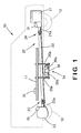
- Fig. 1 a portion of a vehicle, indicated generally at 10, that is generally conventional in the art.
- the vehicle 10 includes a body and frame assembly (a portion of which is illustrated at 11) that is supported upon a plurality of ground-engaging wheels 12 by a resilient suspension system (not shown) and functions as a reference member in the manner described below.
- the vehicle 10 also includes a first embodiment of a drive train system, indicated generally at 20, that is also generally conventional in the art.
- the illustrated drive train system 20 includes an engine/transmission assembly 21 that generates rotational power to an output shaft 21a. Such rotational power is transferred from the output shaft 21a of the engine/transmission assembly 21 through a hollow cylindrical driveshaft tube 22 to an input shaft 23a of an axle assembly 23.
- a device, indicated generally at 30 in Fig. 5, is provided on the vehicle 10 for measuring the operating angles of the universal joints 24 and 25.
- the measuring device 30 includes a first inclinometer 31 that is secured to or otherwise fixed in position relative to the engine/transmission assembly 21, a second inclinometer 32 that is secured to or otherwise fixed in position relative to the portion 11 of the body and frame assembly of the vehicle 10, and a third inclinometer 33 that is secured to or otherwise fixed in position relative to the axle assembly 23.
- Each of the inclinometers 31, 32, and 33 is, of itself, conventional in the art and is adapted to generate an electrical signal that is representative of the angular orientation of the component to which it is secured relative to the horizontal.
- the first inclinometer 31 generates a signal that is representative of the angular orientation of the output shaft 21a of the engine/transmission assembly 21 relative to the horizontal
- the second inclinometer 32 generates a signal that is representative of the angular orientation of the portion 11 of the body and frame assembly of the vehicle 10 relative to the horizontal
- the third inclinometer 33 generates a signal that is representative of the angular orientation of the input shaft 23a of the axle assembly 23.
- a variety of such inclinometers 31, 32, and 33 are commercially available, including the FAS-G gyro enhanced inclinometer that is available from MicroStrain, Inc. of Burlington, Vermont.
- the measuring device 30 also includes an assembly, indicated generally at 34, that is adapted to generate an electrical signal that is representative of the angular orientation of the driveshaft tube 22 relative to the portion 11 of the body and frame assembly of the vehicle 10.
- the structure of the assembly 34 is illustrated in detail in Fig. 2.
- the assembly 34 includes a plurality of structural members 35 that are connected together to form a base.
- the structural members 35 may be formed from any desired material and may have any desired shape.
- the structural members 35 are arranged so that a first portion of the base is disposed on one side of the driveshaft tube 22, while a second portion of the base is disposed on the other side of the driveshaft tube 22 when looking vertically downwardly from above or below the vehicle 10.
- a plurality of mounting fasteners 35a can be used to connect the structural members 35 of the base to the portion 11 of the body and frame assembly of the vehicle 10.
- the structural members 35 of the base are fixed in position relative to the portion 11 of the body and frame assembly of the vehicle 10.
- a pair of mounting brackets 36 and 37 are secured to the structural members 35 on opposite sides of the base.
- each of the mounting brackets 36 and 37 is generally L-shaped, although such is not required.
- the mounting brackets 36 and 37 are preferably disposed on opposite sides of the driveshaft tube 22, although such is not required.
- a first pair of non-contact sensors 36a and 37a are respectively secured to the mounting brackets 36 and 37.
- a second pair of non-contact sensors 36b and 37b are respectively secured to the mounting brackets 36 and 37.
- Each of the non-contact sensors 36a, 36b, 37a, and 37b can be embodied as any device that is capable of sensing the location or distance to the driveshaft tube 22 without physically contacting same.
- the non-contact sensors 37 can be embodied as laser distance sensors, such as commercially available from Memsic, Inc. of Andover, Massachusetts.
- the change in height ( ⁇ y ) of the center point locations will be determined using the non-contact sensors 36a, 36b, 37a, and 37b, while the longitudinal distance ( ⁇ z ) between such center points is fixed by the geometry of the mounting brackets 36 and 37.
- the non-contact sensors 36a, 36b, 37a, and 37b are used to find the coordinates of the necessary center point locations of the driveshaft tube 22, and the difference between the two center point locations (the y coordinates) is the rise ( ⁇ y ).
- the distances measured by the non-contact sensors 36a, 36b, 37a, and 37b be taken at a common point on the driveshaft tube 22.
- the slope of the driveshaft tube 22 be determined from the center point on the interior thereof, rather than from a point on the exterior surface of the driveshaft tube 22. If the laser beams from the non-contact sensors 36a, 36b, 37a, and 37b impinge upon the driveshaft tube 22 shaft at different distances from the x-axis, then a y distance error will be recorded due to the radius of the shaft. This situation is illustrated in Fig. 3.
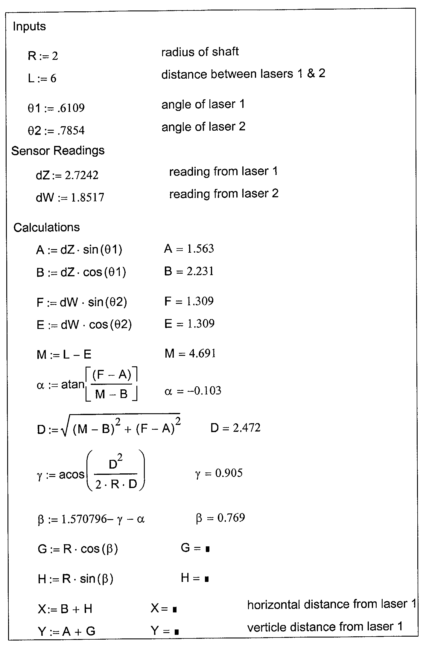
- Fig. 4 illustrates how the center point of the driveshaft tube 22 can be calculated.
- two points along the radius of the driveshaft tube 22 are determined.
- two of the laser sensors 36a and 37a are used to find these two points.
- the points can be determined using knowledge of the angle at which the laser sensors 36a and 37a are positioned, the distance between such laser sensors 36a and 37a, a base coordinate system, and the distance that the laser sensors 36a and 37a are reading.
- the angle at which the laser sensors 36a and 37a are mounted and the distance between the laser sensors 36a and 37a are known values that are determined from the geometry of the structural components 35 of the base.
- the base coordinate system can be chosen at any known position.
- the base coordinate system is chosen as the base point of the laser sensors 36a and 37a that is located in the negative x direction of the center position of the driveshaft tube 22.
- the center point of the driveshaft tube 22 is determined by drawing three triangles connecting the two points on the driveshaft tube 22 and the center of the driveshaft tube 22. Pythagorean's Theorem and the Law of Cosines are then applied to determine the coordinates of the center point of the driveshaft tube 22.
- the radius of the driveshaft tube 22 needs to be known to determine this center location. The following calculations illustrate one method that can be used to find a center point on the driveshaft tube 22.
- the first pair of laser sensors 36a and 37a are used to determined the coordinates of the center point of the driveshaft tube 22 at a first location.
- the second pair of laser sensors 36b and 37b can be used to determined the coordinates of the center point of the driveshaft tube 22 at a second location.
- the change in height ( ⁇ y ) of the center point locations is divided by the longitudinal distance ( ⁇ z ) between such center points (as determined by the geometry of the mounting brackets 36 and 37) represents the angular orientation (or slope) of the driveshaft 22 relative to the portion 11 of the body and frame assembly of the vehicle 10.
- Fig. 5 is a block diagram of the first embodiment of the operating angle measuring device 30 illustrated in Figs. 1 and 2.
- the operating angle measuring device 30 further includes a controller 38 that receives the signals generated by the three inclinometers 31, 32, and 33 and the four laser sensors 36a, 36b, 37a, and 37b.
- the controller 38 is responsive to such signals for calculating the operating angles of the two universal joints 24 and 25 in the drive train system of the vehicle 10.
- the controller 38 can be embodied as any conventional microprocessor or other programmable controller that is responsive to the various input signals for determining the operating angles of the universal joints 24 and 25.
- the first inclinometer 31 generates a signal that is representative of the angular orientation of the output shaft 21a of the engine/transmission assembly 21 relative to the horizontal.
- the output signal from the first inclinometer 31 also represents the angular orientation of the output shaft 21a of the engine/transmission assembly 21 relative to the portion 11 of the body and frame assembly of the vehicle 10.
- the output signal from the first inclinometer 31 does not represent the angular orientation of the output shaft 21a of the engine/transmission assembly 21 relative to the portion 11 of the body and frame assembly of the vehicle 10.
- the signal from the second inclinometer 32 can be subtracted from the signal from the first inclinometer 31 to achieve a signal that represents the angular orientation of the output shaft 21a of the engine/transmission assembly 21 relative to the portion 11 of the body and frame assembly of the vehicle 10.
- a similar calculation can be performed to achieve a signal that represents the angular orientation of the input shaft 23a of the axle assembly 23 relative to the portion 11 of the body and frame assembly of the vehicle 10.
- the assembly 34 is secured to the portion 11 of the body and frame assembly of the vehicle 10. Therefore, the signal that is calculated by the electronic controller 38 in response to the signals from the laser sensors 36a, 36b, 37a, and 37b is representative of the angular orientation of the driveshaft tube 22 relative to the portion 11 of the body and frame assembly of the vehicle 10.
- These operating angles can be calculated and stored in the electronic controller 38 while the vehicle 10 is operated over a period of time in order to gather data regarding the operating angles that are experienced by the universal joints 24 and 25 during such use.
- This operating angle information can be use to insure that the universal joints 24 and 25 of the drive train system 20 are always operated within predetermined design parameters, regardless of variations in the magnitudes of the dynamic movements of the components of the drive train system 20 from vehicle model to vehicle model.
- Fig. 6 schematically illustrates a portion of a modified vehicle, indicated generally at 10', that is similar to the vehicle 10 described above.
- the modified vehicle 10' includes a second embodiment of a drive train system, indicated generally at 20', that is also generally conventional in the art.
- the second embodiment of the drive train system 20' is similar in many respects to the first embodiment of the drive train system 20 described above, and like reference numbers are used to illustrated similar components.
- the second embodiment of the drive train system 20' includes a compound driveshaft that is composed of a first driveshaft tube 22a and a second driveshaft tube 22b that are connected together by a third universal joint, indicated generally at 26.
- a conventional center bearing assembly, indicated generally at 27, is provided for rotatably supporting the first and second driveshaft tubes 22a and 22b on the portion 11 of the body and frame assembly of the vehicle 20'.
- the modified measuring device also includes a first assembly 34a that is adapted to generate an electrical signal that is representative of the angular orientation of the first driveshaft tube 22a relative to the portion 11 of the body and frame assembly of the vehicle 10 and a second assembly 34b that is adapted to generate an electrical signal that is representative of the angular orientation of the second driveshaft tube 22b relative to the portion 11 of the body and frame assembly of the vehicle 10.
- the structure of the two assemblies 34a and 34b is illustrated in detail in Fig. 7. As shown therein, the assemblies 34a and 34b may be constructed as a single unit by a pair of interconnecting struts 34c that are, in turn, secured to the portion 11 of the body and frame assembly of the vehicle 10', although such is not required.
- the assemblies 34a and 34b each function in the same manner as described above and can be used to determine the operating angles of not only the first and second universal joints 24 and 25, but also the operating angle of the third universal joint 26.
Landscapes
- Engineering & Computer Science (AREA)
- Physics & Mathematics (AREA)
- General Physics & Mathematics (AREA)
- Manufacturing & Machinery (AREA)
- Chemical & Material Sciences (AREA)
- Combustion & Propulsion (AREA)
- Transportation (AREA)
- Mechanical Engineering (AREA)
- Length Measuring Devices With Unspecified Measuring Means (AREA)
- Length Measuring Devices By Optical Means (AREA)
Abstract
Description
Claims (10)
- A device for measuring the angular orientation of a shaft comprising:a first sensor for generating a first sensor signal that is representative of a first point on the shaft;a second sensor for generating a second sensor signal that is representative of a second point on the shaft; anda controller that is responsive to said first and second sensor signals for determining the angular orientation of the shaft.
- The device defined in Claim 1 wherein said first and second sensors are non-contact sensors.
- The device defined in Claim 1 wherein said first and second sensors are laser distance sensors.
- The device defined in Claim 1 wherein said first sensor includes a first pair of sensors, and wherein said second sensor includes a second pair of sensors.
- The device defined in Claim 1 wherein said first sensor signal is representative of a first center point on the interior of the shaft, and wherein said second sensor signal is representative of a second center point on the interior of the shaft.
- The device defined in Claim 1 wherein said controller is responsive to said first and second sensor signals and to a signal that is representative of a distance between said first and second sensors for determining the angular orientation of the shaft.
- The device defined in Claim 1 further including a third sensor that generates a third sensor signal that is representative of the angular orientation of a reference member, and wherein said controller is responsive to said first, second, and third sensor signals for determining the angular orientation of the shaft relative to the reference member.
- The device defined in Claim 1 wherein the shaft includes first and second shaft portions, said first sensor generates a first sensor signal that is representative of a first point on the first shaft portion, said second sensor generates a second sensor signal that is representative of a second point on the first shaft portion, and said controller is responsive to said first and second sensor signals for determining the angular orientation of the first shaft portion.
- The device defined in Claim 8 further including a third sensor that generates a third sensor signal that is representative of a first point on the second shaft portion, a fourth sensor that generates a fourth sensor signal that is representative of a second point on the second shaft portion, and said controller is responsive to said third and fourth sensor signals for determining the angular orientation of the second shaft portion.
- The device defined in Claim 9 wherein said controller is responsive to said first, second, third, and fourth sensor signals for determining an operating angle between the first and second shaft portions.
Applications Claiming Priority (2)
| Application Number | Priority Date | Filing Date | Title |
|---|---|---|---|
| US37707602P | 2002-04-30 | 2002-04-30 | |
| US377076P | 2002-04-30 |
Publications (2)
| Publication Number | Publication Date |
|---|---|
| EP1359387A2 true EP1359387A2 (en) | 2003-11-05 |
| EP1359387A3 EP1359387A3 (en) | 2003-12-03 |
Family
ID=29215909
Family Applications (1)
| Application Number | Title | Priority Date | Filing Date |
|---|---|---|---|
| EP03252691A Withdrawn EP1359387A3 (en) | 2002-04-30 | 2003-04-29 | Device for measuring universal joint operating angles in a drive train system |
Country Status (4)
| Country | Link |
|---|---|
| US (1) | US20040093960A1 (en) |
| EP (1) | EP1359387A3 (en) |
| AU (1) | AU2003203925A1 (en) |
| BR (1) | BR0301066A (en) |
Cited By (3)
| Publication number | Priority date | Publication date | Assignee | Title |
|---|---|---|---|---|
| CN110411402A (en) * | 2019-08-13 | 2019-11-05 | 上海元城汽车技术有限公司 | A kind of measurement method of semiaxis angle |
| CN110749292A (en) * | 2018-07-23 | 2020-02-04 | 宝钢新日铁汽车板有限公司 | Online air knife angle detection device and method |
| CN111637852A (en) * | 2020-05-27 | 2020-09-08 | 中国汽车技术研究中心有限公司 | System and method for measuring articulation angle of full-trailer automobile train |
Families Citing this family (2)
| Publication number | Priority date | Publication date | Assignee | Title |
|---|---|---|---|---|
| WO2013043190A1 (en) * | 2011-09-23 | 2013-03-28 | Volvo Group North America, Llc | Driveline angle measurement system and method |
| CN118482943A (en) * | 2024-05-30 | 2024-08-13 | 江铃汽车股份有限公司 | A dynamic angle test method for powertrain transmission system |
Family Cites Families (11)
| Publication number | Priority date | Publication date | Assignee | Title |
|---|---|---|---|---|
| CH557542A (en) * | 1972-10-27 | 1974-12-31 | Saurer Ag Adolph | ROTATION ANGLE MEASURING DEVICE ON A MACHINE WITH A ROTATING SHAFT. |
| US4272892A (en) * | 1979-08-10 | 1981-06-16 | Omnicomp, Inc. | Automatic test probe positioning apparatus |
| US4507834A (en) * | 1983-05-27 | 1985-04-02 | Sperry Corporation | Drilling monitor |
| US4844609A (en) * | 1988-01-29 | 1989-07-04 | Michael P. McGarry | Apparatus and method for aligning elements of a drive train of a vehicle, especially a heavy-duty, load-carrying vehicle |
| US5734108A (en) * | 1992-04-10 | 1998-03-31 | Walker; Dana A. | System for sensing shaft displacement and strain |
| US5684578A (en) * | 1994-06-23 | 1997-11-04 | Computational Systems, Inc. | Laser alignment head for use in shaft alignment |
| US5703796A (en) * | 1996-07-11 | 1997-12-30 | Ford Global Technologies, Inc. | Driveline alignment apparatus and method |
| EP0894240B1 (en) * | 1997-01-22 | 2003-08-27 | Prüftechnik Dieter Busch Ag | Electro-optical measuring device for determining the relative position of two bodies, or of two surface areas of bodies, in relation to each other |
| US6082190A (en) * | 1998-07-21 | 2000-07-04 | Dana Corporation | Adapter for facilitating the measurement of the angular orientation of vehicle drive train components |
| US6441908B1 (en) * | 1999-08-06 | 2002-08-27 | Metron Systems, Inc. | Profiling of a component having reduced sensitivity to anomalous off-axis reflections |
| US6426497B1 (en) * | 1999-12-30 | 2002-07-30 | Honeywell International Inc. | Method and system for optical distance and angle measurement |
-
2003
- 2003-04-29 EP EP03252691A patent/EP1359387A3/en not_active Withdrawn
- 2003-04-29 AU AU2003203925A patent/AU2003203925A1/en not_active Abandoned
- 2003-04-29 BR BR0301066-0A patent/BR0301066A/en not_active Application Discontinuation
- 2003-04-30 US US10/427,718 patent/US20040093960A1/en not_active Abandoned
Cited By (5)
| Publication number | Priority date | Publication date | Assignee | Title |
|---|---|---|---|---|
| CN110749292A (en) * | 2018-07-23 | 2020-02-04 | 宝钢新日铁汽车板有限公司 | Online air knife angle detection device and method |
| CN110411402A (en) * | 2019-08-13 | 2019-11-05 | 上海元城汽车技术有限公司 | A kind of measurement method of semiaxis angle |
| CN110411402B (en) * | 2019-08-13 | 2021-08-06 | 上海元城汽车技术有限公司 | Method for measuring included angle of half shaft |
| CN111637852A (en) * | 2020-05-27 | 2020-09-08 | 中国汽车技术研究中心有限公司 | System and method for measuring articulation angle of full-trailer automobile train |
| CN111637852B (en) * | 2020-05-27 | 2023-03-21 | 中国汽车技术研究中心有限公司 | System and method for measuring articulation angle of full-trailer automobile train |
Also Published As
| Publication number | Publication date |
|---|---|
| AU2003203925A1 (en) | 2003-11-20 |
| US20040093960A1 (en) | 2004-05-20 |
| EP1359387A3 (en) | 2003-12-03 |
| BR0301066A (en) | 2005-03-01 |
Similar Documents
| Publication | Publication Date | Title |
|---|---|---|
| US7463953B1 (en) | Method for determining a tilt angle of a vehicle | |
| US5559696A (en) | Mobile robot internal position error correction system | |
| US7340368B2 (en) | Determination of dynamic axle loads and/or wheel loads of a wheel vehicle | |
| JP3074464B2 (en) | Road profile measurement device | |
| CN1239919A (en) | System and method for detection of vehicle rollover conditions | |
| MXPA01012685A (en) | Apparatus and method for a pitch state estimator for a personal vehicle. | |
| JP2016512322A (en) | Method, system and apparatus for evaluating vehicle wheel condition | |
| JP2004518120A (en) | Dynamic direction determination system for vehicle wheel surface | |
| US6204499B1 (en) | Method and apparatus for a rotation angle sensor | |
| US5218556A (en) | Steering pivot axis orientation measurement apparatus and method | |
| CN87105273A (en) | In train operation, measure antagonistic force, especially for examining the method and apparatus of railway track state | |
| JP4149913B2 (en) | Integrated inertia VMS navigation with inertia odometer correction | |
| EP1359387A2 (en) | Device for measuring universal joint operating angles in a drive train system | |
| CN100443318C (en) | Determination of relative movement of chassis and body of wheeled vehicle | |
| EP1387144A1 (en) | Dynamic measurement of an object's relative position, in particular of a wheel of a vehicle | |
| US7353697B2 (en) | System for mounting an engine to a frame | |
| CN101228423B (en) | Measuring devices for automobiles | |
| JP4386985B2 (en) | In-vehicle measuring device for road surface extension | |
| RU2112829C1 (en) | Device for measuring coefficient of adhesion between wheels of vehicle and pavement surface | |
| US7581329B2 (en) | Dynamic percent grade measurement device | |
| EP0845388A1 (en) | Device for sensing the pitch angle, particularly for automatically correcting the attitude of the headlights of a vehicle | |
| CN116147747A (en) | Vehicle weight measuring method and system based on mems attitude sensor | |
| JP2009504483A (en) | Load sensing wheel support knuckle assembly and usage | |
| WO1998025106A1 (en) | Wheel alignment system | |
| JP2025536819A (en) | Dynamic vehicle attitude measurement device |
Legal Events
| Date | Code | Title | Description |
|---|---|---|---|
| PUAI | Public reference made under article 153(3) epc to a published international application that has entered the european phase |
Free format text: ORIGINAL CODE: 0009012 |
|
| PUAL | Search report despatched |
Free format text: ORIGINAL CODE: 0009013 |
|
| AK | Designated contracting states |
Kind code of ref document: A2 Designated state(s): AT BE BG CH CY CZ DE DK EE ES FI FR GB GR HU IE IT LI LU MC NL PT RO SE SI SK TR |
|
| AX | Request for extension of the european patent |
Extension state: AL LT LV MK |
|
| AK | Designated contracting states |
Kind code of ref document: A3 Designated state(s): AT BE BG CH CY CZ DE DK EE ES FI FR GB GR HU IE IT LI LU MC NL PT RO SE SI SK TR |
|
| AX | Request for extension of the european patent |
Extension state: AL LT LV MK |
|
| AKX | Designation fees paid | ||
| REG | Reference to a national code |
Ref country code: DE Ref legal event code: 8566 |
|
| STAA | Information on the status of an ep patent application or granted ep patent |
Free format text: STATUS: THE APPLICATION IS DEEMED TO BE WITHDRAWN |
|
| 18D | Application deemed to be withdrawn |
Effective date: 20040604 |