US7581329B2 - Dynamic percent grade measurement device - Google Patents
Dynamic percent grade measurement device Download PDFInfo
- Publication number
- US7581329B2 US7581329B2 US11/740,142 US74014207A US7581329B2 US 7581329 B2 US7581329 B2 US 7581329B2 US 74014207 A US74014207 A US 74014207A US 7581329 B2 US7581329 B2 US 7581329B2
- Authority
- US
- United States
- Prior art keywords
- rocker arm
- displacement
- measurement device
- equal
- measurement
- Prior art date
- Legal status (The legal status is an assumption and is not a legal conclusion. Google has not performed a legal analysis and makes no representation as to the accuracy of the status listed.)
- Expired - Fee Related, expires
Links
- 238000005259 measurement Methods 0.000 title claims abstract description 61
- 238000006073 displacement reaction Methods 0.000 claims abstract description 66
- 238000000034 method Methods 0.000 claims description 13
- 230000005484 gravity Effects 0.000 claims description 11
- 238000002604 ultrasonography Methods 0.000 claims description 3
- 230000001133 acceleration Effects 0.000 description 2
- 230000002596 correlated effect Effects 0.000 description 1
- 238000012986 modification Methods 0.000 description 1
- 230000004048 modification Effects 0.000 description 1
- 230000003068 static effect Effects 0.000 description 1
Images

Classifications
-
- G—PHYSICS
- G01—MEASURING; TESTING
- G01C—MEASURING DISTANCES, LEVELS OR BEARINGS; SURVEYING; NAVIGATION; GYROSCOPIC INSTRUMENTS; PHOTOGRAMMETRY OR VIDEOGRAMMETRY
- G01C9/00—Measuring inclination, e.g. by clinometers, by levels
- G01C9/02—Details
-
- B—PERFORMING OPERATIONS; TRANSPORTING
- B60—VEHICLES IN GENERAL
- B60G—VEHICLE SUSPENSION ARRANGEMENTS
- B60G2400/00—Indexing codes relating to detected, measured or calculated conditions or factors
- B60G2400/80—Exterior conditions
- B60G2400/82—Ground surface
-
- B—PERFORMING OPERATIONS; TRANSPORTING
- B60—VEHICLES IN GENERAL
- B60W—CONJOINT CONTROL OF VEHICLE SUB-UNITS OF DIFFERENT TYPE OR DIFFERENT FUNCTION; CONTROL SYSTEMS SPECIALLY ADAPTED FOR HYBRID VEHICLES; ROAD VEHICLE DRIVE CONTROL SYSTEMS FOR PURPOSES NOT RELATED TO THE CONTROL OF A PARTICULAR SUB-UNIT
- B60W2552/00—Input parameters relating to infrastructure
- B60W2552/15—Road slope, i.e. the inclination of a road segment in the longitudinal direction
Definitions
- the invention relates generally to a percent grade measurement device.
- Motor vehicle leveling systems are known. Typically, vehicles are leveled by first sensing the degree of vehicle tilt along at least one axis that is disposed parallel to the tilt line that extends along the vehicle. The degree of tilt is determined to be the angle sensed along the respective axis as indicated by the output of the tilt sensor.
- leveling systems are unable to respond to vehicle dynamics and also cannot contemplate variable ground conditions, such as a change in the percent grade experienced at the point of ground contact.
- leveling systems are only able to accurately measure along the attitude of a vehicle along an axis upon which the tilt sensor is supported.
- a dynamic measurement device for measuring the grade of terrain under the wheel of a vehicle as the vehicle traverses over the terrain is provided according to the various embodiments of the present disclosure.
- the dynamic measurement device measures localized grade changes on a scale more closely related to the size of the vehicle wheel.
- the measurements may be captured while the vehicle is moving. The measurements may then be time correlated with any other measurements of vehicle operating parameters. This allows much more specific information to be gathered on vehicle performance and events relative to very specific terrain events.
- a combination of components for the dynamic measurement of the grade of terrain.
- the components include a rocker arm disposed horizontally across a reference structure, the rocker arm having a first end and a second end; a first displacement transducer positioned at the first end of the rocker arm and a second displacement transducer positioned at the second end of the rocker arm.
- the first and second displacement transducers are positioned equidistant from a vertical centerline of the rocker arm.
- An absolute angle measurement device is positioned on the reference structure to provide the angle of the rocker arm relative to earth horizontal.
- a method for the dynamic measurement of the grade of terrain including providing a rocker arm disposed horizontally across a reference structure, the rocker arm having a first end and a second end; measuring a first displacement using a first displacement transducer positioned at the first end of the rocker arm; measuring a second displacement using a second displacement transducer positioned at the second end of the rocker arm, the first and second displacement transducers equidistant from a vertical centerline of said rocker arm; measuring the rise over run of the angle of the rocker arm relative to earth horizontal; and calculating a percent grade measurement using the first displacement, second displacement and rise over run of the angle of the rocker arm relative to earth horizontal measurements.
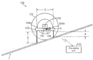
- FIG. 1 is a simplified illustration of a measurement device in accordance with an embodiment of the present invention.
- FIG. 1 is a simplified illustration of a measurement device 100 in accordance with an embodiment of the present disclosure.
- Measurement device 100 provides dynamic measurements of the grade of terrain T under a reference structure, such as the wheel of a moving vehicle.
- measurement device 100 is appropriately mounted on a reference structure to be measured, for example, wheel 101 . It should be understood that measurement device 100 does not need to be mounted directly on the reference structure to be effective, but may be mounted on a frame or other structure positioned ahead or behind the reference structure.
- Measurement device 100 may include a balanced rocker arm 102 , first and second non-contacting displacement transducers 104 a and 104 b , and tilt sensor 106 to measure the absolute angle with respect to gravity.
- the methodology used for either the non-contacting displacement transducers 104 or tilt sensor 106 may vary with respect to the application.
- rocker arm 102 extends along the beam width of wheel 101 .
- Rocker arm 102 is allowed to swing or pivot with respect to wheel 101 so as to maintain a generally level relationship with respect to gravity.
- rocker arm 102 extends along the beam width of wheel 101 .
- Rocker arm 102 is allowed to pivot with respect to wheel 101 , yet maintains a generally level relationship with respect to gravity, as wheel 101 traverses terrain T.
- a ballast weight 108 is coupled below the point of rotation 110 of rocker arm 102 , which adds stability to the orientation of rocker arm 102 .
- a rotational damper positioned at pivot point 110 may be used, while wheel 101 is traversing terrain T, to further reduce any swinging or pivoting movement experienced by rocker arm 102 during, for example, the lateral acceleration and deceleration of wheel 101 . This results in providing an increasingly stable reference platform for horizontal and vertical measurement with respect to gravity.
- a pivot-centered, differential displacement measurement may be made with respect to terrain T, using first and second displacement transducers 104 a and 104 b.
- Displacement transducers 104 a and 104 b may be mounted on rocker arm 102 in any desired position along the beam width thereof. Accordingly, rocker arm 102 may then be balanced, if necessary, in a manner known to those of ordinary skill in the art to compensate for the positioning.
- displacement transducers 104 a and 104 b may be mounted toward the ends of rocker arm 102 on wheel 101 , centered across the beam width thereof and equidistant from the center line between the center of the pivot point 110 and the center of gravity of ballast weight 108 .
- rocker arm 102 is conveniently balanced.
- the distance between displacement transducers 104 a and 104 b defines the granularity of the percent grade measurement.
- Each sensor 104 a and 104 b measures the distance between its location on rocker arm 102 and terrain T. For example as shown in FIG. 1 , distance A is equal to the distance to terrain T from displacement transducer 104 a . Distance B is the measure of the distance to terrain T from displacement transducer 104 b.
- Displacement transducers 104 a and 104 b may be any conventional displacement transducers and may operate using laser and ultrasound. Suitable laser transducers are available commercially from, for example, Scantron Industrial Products Ltd, Taunton, England and ultrasonic transducers are commercially available from Senix Corporation, Bristol, Vt., USA.
- eddy current transducers are available from MICRO-EPSILON MESSTECHNIK GmbH & Co.
- Tilt sensor 106 may be used to measure the rotational instability (i.e. swinging motion) of rocker arm 102 caused by the lateral acceleration and deceleration of wheel 101 .
- a rotational damper may be used at rotation point 110 to help improve the generally level orientation of the rocker arm 102 while wheel 101 traverses terrain
- tilt sensor 106 may be used to compensate for the difference, by indicating the real-time angle of rocker arm 102 with respect to gravity.
- the data from tilt sensor 106 may be used to account for the instability of rocker arm 102 , either directly or computationally.
- tilt sensor 106 may be used to account for any offsets from the level reference, especially when wheel 101 is static, caused, for example, by the imprecise placement of any components of measurement device 100 .
- Tilt sensor 106 may be any type of conventional tilt sensor, for example, an inclinometer, DC accelerometer, magnetometer, gyro, electrolytic tilt sensor, capacitive inclination device, and force balance accelerometer.
- displacement transducers 104 a and 104 b and tilt sensor 106 make measurement device 100 functional for the purposes intended.
- the signals provided by displacement transducers 104 a and 104 b and tilt sensor 106 are recorded and processed to provide raw measurement data.
- the raw data may be stored and processed at wheel 101 , for example, with an on-board processing unit 120 or the data may be transmitted via flexible wires or wirelessly to a remote processing unit 120 , as shown in FIG. 1 .
- the raw measurement data may be used in an algorithm to provide a percent grade measurement of terrain T experienced at wheel 101 .
- % Grade ((( B ⁇ A )/ C ) ⁇ D ) ⁇ 100 where A is equal to the distance to terrain T from displacement transducer 104 a , B is equal to the distance to terrain T from displacement transducer 104 b , C is equal to the distance between the two displacement transducers 104 a and 104 b , and D is equal to the rise over run of the angle of rocker arm 102 relative to earth horizontal as measured by tilt sensor 106 .
Landscapes
- Physics & Mathematics (AREA)
- Engineering & Computer Science (AREA)
- General Physics & Mathematics (AREA)
- Radar, Positioning & Navigation (AREA)
- Remote Sensing (AREA)
- Length Measuring Devices With Unspecified Measuring Means (AREA)
Abstract
Description
% Grade=(((B−A)/C)−D)×100
where A is equal to the distance to terrain T from
Claims (20)
% Grade=(((B−A)/C)−D)×100
% Grade=(((B−A)/C)−D)×100
% Grade=(((B−A)/C)−D)×100
Priority Applications (2)
| Application Number | Priority Date | Filing Date | Title |
|---|---|---|---|
| US11/740,142 US7581329B2 (en) | 2007-04-25 | 2007-04-25 | Dynamic percent grade measurement device |
| GB0807490A GB2448820B (en) | 2007-04-25 | 2008-04-24 | Dynamic percent grade measurement device |
Applications Claiming Priority (1)
| Application Number | Priority Date | Filing Date | Title |
|---|---|---|---|
| US11/740,142 US7581329B2 (en) | 2007-04-25 | 2007-04-25 | Dynamic percent grade measurement device |
Publications (2)
| Publication Number | Publication Date |
|---|---|
| US20080263881A1 US20080263881A1 (en) | 2008-10-30 |
| US7581329B2 true US7581329B2 (en) | 2009-09-01 |
Family
ID=39522492
Family Applications (1)
| Application Number | Title | Priority Date | Filing Date |
|---|---|---|---|
| US11/740,142 Expired - Fee Related US7581329B2 (en) | 2007-04-25 | 2007-04-25 | Dynamic percent grade measurement device |
Country Status (2)
| Country | Link |
|---|---|
| US (1) | US7581329B2 (en) |
| GB (1) | GB2448820B (en) |
Cited By (3)
| Publication number | Priority date | Publication date | Assignee | Title |
|---|---|---|---|---|
| US8696237B2 (en) | 2011-06-15 | 2014-04-15 | Joseph Vogele Ag | Road paver with layer thickness measuring device |
| US8702344B2 (en) | 2011-06-15 | 2014-04-22 | Joseph Vogele Ag | Road paver with layer thickness measuring device |
| US9033611B2 (en) | 2011-06-15 | 2015-05-19 | Joseph Vogele Ag | Road paver with layer thickness measuring device |
Families Citing this family (1)
| Publication number | Priority date | Publication date | Assignee | Title |
|---|---|---|---|---|
| US8028433B1 (en) * | 2010-10-14 | 2011-10-04 | Holland Carl A | Method and device for measuring the inclination of a roadway |
Citations (13)
| Publication number | Priority date | Publication date | Assignee | Title |
|---|---|---|---|---|
| US4490919A (en) * | 1981-04-01 | 1985-01-01 | Wieland Feist | Leveling arrangement for measuring terrain points |
| JPH01208289A (en) | 1988-02-15 | 1989-08-22 | Stanley Electric Co Ltd | Motorcycle tilt angle detection device |
| JPH09178479A (en) * | 1995-12-27 | 1997-07-11 | Suzuki Motor Corp | Tilt angle measuring device |
| DE19650629A1 (en) | 1996-12-06 | 1998-06-10 | Telefunken Microelectron | Vehicle tilt measurement, especially for motor vehicle |
| US6119353A (en) * | 1995-04-03 | 2000-09-19 | Greenwood Engineering Aps | Method and apparatus for non-contact measuring of the deflection of roads or rails |
| JP2000283745A (en) * | 1999-03-31 | 2000-10-13 | Komatsu Engineering Kk | On-board device for measuring shape in road surface extension direction |
| US20020013644A1 (en) * | 2000-03-06 | 2002-01-31 | Mekemson James R. | Method and apparatus for pavement cross-slope measurement |
| EP1300287A2 (en) | 2001-09-28 | 2003-04-09 | Audi Ag | Device and method for determining the inclination of a vehicle and controlling the lighting distance |
| US6618954B2 (en) * | 2000-05-30 | 2003-09-16 | Tokimec Construction Systems Inc. | Longitudinal profile measuring apparatus |
| US6688167B2 (en) * | 1999-12-17 | 2004-02-10 | Laboratoire Centrao Des Ponts Et Chaussees | Measuring the profile of a pavement by moving three contactless distance-measuring sensors |
| US6714483B2 (en) * | 2002-02-15 | 2004-03-30 | Mitsubishi Denki Kabushiki Kaisha | Inclination angle measurement apparatus |
| US20040173033A1 (en) * | 2001-07-07 | 2004-09-09 | David Gilbert | Track monitoring equipment |
| US6912478B1 (en) * | 2003-08-12 | 2005-06-28 | Allen Face And Company, Lc | System for collecting data used by surface profiling scheme |
-
2007
- 2007-04-25 US US11/740,142 patent/US7581329B2/en not_active Expired - Fee Related
-
2008
- 2008-04-24 GB GB0807490A patent/GB2448820B/en not_active Expired - Fee Related
Patent Citations (14)
| Publication number | Priority date | Publication date | Assignee | Title |
|---|---|---|---|---|
| US4490919A (en) * | 1981-04-01 | 1985-01-01 | Wieland Feist | Leveling arrangement for measuring terrain points |
| JPH01208289A (en) | 1988-02-15 | 1989-08-22 | Stanley Electric Co Ltd | Motorcycle tilt angle detection device |
| US6119353A (en) * | 1995-04-03 | 2000-09-19 | Greenwood Engineering Aps | Method and apparatus for non-contact measuring of the deflection of roads or rails |
| JPH09178479A (en) * | 1995-12-27 | 1997-07-11 | Suzuki Motor Corp | Tilt angle measuring device |
| DE19650629A1 (en) | 1996-12-06 | 1998-06-10 | Telefunken Microelectron | Vehicle tilt measurement, especially for motor vehicle |
| JP2000283745A (en) * | 1999-03-31 | 2000-10-13 | Komatsu Engineering Kk | On-board device for measuring shape in road surface extension direction |
| US6688167B2 (en) * | 1999-12-17 | 2004-02-10 | Laboratoire Centrao Des Ponts Et Chaussees | Measuring the profile of a pavement by moving three contactless distance-measuring sensors |
| US20020013644A1 (en) * | 2000-03-06 | 2002-01-31 | Mekemson James R. | Method and apparatus for pavement cross-slope measurement |
| US7142952B2 (en) * | 2000-03-06 | 2006-11-28 | Mekemson James R | Method and apparatus for pavement cross-slope measurement |
| US6618954B2 (en) * | 2000-05-30 | 2003-09-16 | Tokimec Construction Systems Inc. | Longitudinal profile measuring apparatus |
| US20040173033A1 (en) * | 2001-07-07 | 2004-09-09 | David Gilbert | Track monitoring equipment |
| EP1300287A2 (en) | 2001-09-28 | 2003-04-09 | Audi Ag | Device and method for determining the inclination of a vehicle and controlling the lighting distance |
| US6714483B2 (en) * | 2002-02-15 | 2004-03-30 | Mitsubishi Denki Kabushiki Kaisha | Inclination angle measurement apparatus |
| US6912478B1 (en) * | 2003-08-12 | 2005-06-28 | Allen Face And Company, Lc | System for collecting data used by surface profiling scheme |
Non-Patent Citations (3)
| Title |
|---|
| "Bruton Pocket Transit Instruction Manual"; The Brunton Company; Copyright 2000. |
| Translations of JP2000283745A and JP09178479A from machine translator retrieved Oct. 21, 2008. * |
| UK Search Report on corresponding GB patent application (GB0807490.8) from UK Intellectual Property Office dated Aug. 6, 2008. |
Cited By (3)
| Publication number | Priority date | Publication date | Assignee | Title |
|---|---|---|---|---|
| US8696237B2 (en) | 2011-06-15 | 2014-04-15 | Joseph Vogele Ag | Road paver with layer thickness measuring device |
| US8702344B2 (en) | 2011-06-15 | 2014-04-22 | Joseph Vogele Ag | Road paver with layer thickness measuring device |
| US9033611B2 (en) | 2011-06-15 | 2015-05-19 | Joseph Vogele Ag | Road paver with layer thickness measuring device |
Also Published As
| Publication number | Publication date |
|---|---|
| US20080263881A1 (en) | 2008-10-30 |
| GB2448820B (en) | 2011-10-19 |
| GB0807490D0 (en) | 2008-06-04 |
| GB2448820A (en) | 2008-10-29 |
Similar Documents
| Publication | Publication Date | Title |
|---|---|---|
| KR101299828B1 (en) | Method for determining at least one displacement state of a vehicle body | |
| EP0575327B1 (en) | A method and an apparatus for measuring curvature and crossfall of ground surfaces | |
| US6419240B1 (en) | Vehicle roll control | |
| RU2630703C2 (en) | Aggregate for delivery of liquid and/or solid active substances and management method for such aggregate | |
| CN104169697B (en) | Method and system for determining wading depth of a vehicle | |
| US7463953B1 (en) | Method for determining a tilt angle of a vehicle | |
| AU2018246236B2 (en) | Track geometry measurement system with inertial measurement | |
| JP7146814B2 (en) | Track Inspection Vehicles and Methods for Detecting Vertical Track Position | |
| KR102363031B1 (en) | height measuring device for vehicle | |
| JP2011526859A (en) | Vehicle wheel suspension | |
| AU2019309447B2 (en) | Method for determining an angle of a tool of a machine | |
| ITTO20100720A1 (en) | SYSTEM AND METHOD OF MEASURING THE ROUGHNESS OF A ROAD SURFACE | |
| CN1209529C (en) | Rail construction machinery for measuring rail position and operating method | |
| US7581329B2 (en) | Dynamic percent grade measurement device | |
| CN108426557A (en) | A kind of rail smooth detection method and device | |
| JPH10168810A (en) | Road profile measurement device | |
| US7100289B1 (en) | Microelectronic vehicle service system sensor | |
| JPH02293636A (en) | Method and apparatus for detecting axial load for vehicle | |
| JP2022507983A (en) | WIM sensor calibration | |
| KR101356347B1 (en) | Inertial navigation system of walk and method for estimating angle and height information using the same | |
| CN109211234B (en) | Underground inertial surveying and mapping method and device | |
| JPH08297033A (en) | Navigation device | |
| EP2453203A1 (en) | Orientation sensor | |
| JP2009040354A (en) | Suspension characteristics estimation device | |
| KR20090036325A (en) | Apparatus and method for measuring the moving speed of a moving object in a navigation device |
Legal Events
| Date | Code | Title | Description |
|---|---|---|---|
| AS | Assignment |
Owner name: THE BOEING COMPANY, ILLINOIS Free format text: ASSIGNMENT OF ASSIGNORS INTEREST;ASSIGNOR:BASHAM, RICHARD R.;REEL/FRAME:019211/0587 Effective date: 20070412 |
|
| STCF | Information on status: patent grant |
Free format text: PATENTED CASE |
|
| FPAY | Fee payment |
Year of fee payment: 4 |
|
| FPAY | Fee payment |
Year of fee payment: 8 |
|
| FEPP | Fee payment procedure |
Free format text: MAINTENANCE FEE REMINDER MAILED (ORIGINAL EVENT CODE: REM.); ENTITY STATUS OF PATENT OWNER: LARGE ENTITY |
|
| LAPS | Lapse for failure to pay maintenance fees |
Free format text: PATENT EXPIRED FOR FAILURE TO PAY MAINTENANCE FEES (ORIGINAL EVENT CODE: EXP.); ENTITY STATUS OF PATENT OWNER: LARGE ENTITY |
|
| STCH | Information on status: patent discontinuation |
Free format text: PATENT EXPIRED DUE TO NONPAYMENT OF MAINTENANCE FEES UNDER 37 CFR 1.362 |
|
| FP | Lapsed due to failure to pay maintenance fee |
Effective date: 20210901 |