EP1359327A1 - Axial fan for vehicle - Google Patents
Axial fan for vehicle Download PDFInfo
- Publication number
- EP1359327A1 EP1359327A1 EP02711387A EP02711387A EP1359327A1 EP 1359327 A1 EP1359327 A1 EP 1359327A1 EP 02711387 A EP02711387 A EP 02711387A EP 02711387 A EP02711387 A EP 02711387A EP 1359327 A1 EP1359327 A1 EP 1359327A1
- Authority
- EP
- European Patent Office
- Prior art keywords
- blades
- boss
- air
- axial
- axial fan
- Prior art date
- Legal status (The legal status is an assumption and is not a legal conclusion. Google has not performed a legal analysis and makes no representation as to the accuracy of the status listed.)
- Granted
Links
Images




Classifications
-
- F—MECHANICAL ENGINEERING; LIGHTING; HEATING; WEAPONS; BLASTING
- F04—POSITIVE - DISPLACEMENT MACHINES FOR LIQUIDS; PUMPS FOR LIQUIDS OR ELASTIC FLUIDS
- F04D—NON-POSITIVE-DISPLACEMENT PUMPS
- F04D29/00—Details, component parts, or accessories
- F04D29/58—Cooling; Heating; Diminishing heat transfer
- F04D29/582—Cooling; Heating; Diminishing heat transfer specially adapted for elastic fluid pumps
-
- F—MECHANICAL ENGINEERING; LIGHTING; HEATING; WEAPONS; BLASTING
- F04—POSITIVE - DISPLACEMENT MACHINES FOR LIQUIDS; PUMPS FOR LIQUIDS OR ELASTIC FLUIDS
- F04D—NON-POSITIVE-DISPLACEMENT PUMPS
- F04D29/00—Details, component parts, or accessories
- F04D29/26—Rotors specially for elastic fluids
- F04D29/32—Rotors specially for elastic fluids for axial flow pumps
- F04D29/325—Rotors specially for elastic fluids for axial flow pumps for axial flow fans
-
- F—MECHANICAL ENGINEERING; LIGHTING; HEATING; WEAPONS; BLASTING
- F04—POSITIVE - DISPLACEMENT MACHINES FOR LIQUIDS; PUMPS FOR LIQUIDS OR ELASTIC FLUIDS
- F04D—NON-POSITIVE-DISPLACEMENT PUMPS
- F04D29/00—Details, component parts, or accessories
- F04D29/26—Rotors specially for elastic fluids
- F04D29/32—Rotors specially for elastic fluids for axial flow pumps
- F04D29/325—Rotors specially for elastic fluids for axial flow pumps for axial flow fans
- F04D29/329—Details of the hub
Definitions
- the present invention relates to an axial fan, for vehicles, having a plurality of blades radially extending from a boss (hub).
- a radiator, and a blower for blowing cold air onto the radiator have usually been mounted on the portions where the air can be easily taken in, such as at the front end of the vehicle. Therefore, the blower is strongly affected by the air pressure caused by travelling of the vehicle.
- the axial fan used for the blower is such that the air passes through in the axial direction.
- the velocity differential becomes small between the surfaces of the blades and the air, and the resistance becomes small between the blade surfaces and the air.
- the spatial size W1 through which the air substantially flows becomes smaller than the spatial size Wo in which the air substantially flows when the air that is blown is flowing in the axial direction, resulting in a decrease in the blow rate and in the fan efficiency of the blower.
- This phenomenon occurs particularly conspicuously when there exists a wall surface having a large air resistance, such as an engine, on the downstream side of the axial fan.
- an object of the present invention to provide an axial fan for vehicles, which suppresses a drop in the flow rate that occurs when the air that is blown does not flow in the axial direction but flows in the outer radial direction.
- an axial fan 210 having a plurality of blades 212 radially extending from a boss 211 to blow the air to a heat exchanger 100 mounted on the vehicle, wherein the axial end surface 211a of the boss 211 on the negative pressure side 212 of the blades 212 is so constituted that the air flows toward the root side of the blades 212 from the side of the axial end surface 211a.
- the resistance decreases between the air and the blade surfaces on the root side of the blades 212, making it possible to prevent a stall on the root side of the blades 212. It is, therefore, possible to effectively make the air on the front side of the boss 211 flow toward the outer direction (toward the blades 212) and, hence, to suppress a drop in the flow rate.
- an axial fan 210 having a plurality of blades 212 radially extending from a boss 211 to blow the air to a heat exchanger 100 mounted on the vehicle, wherein the front edges 212b of the blades 212 are deviated toward the upstream side in the air stream beyond the axial end surface 211a at the axial end of the boss 211 as viewed from a direction at right angles to the axial direction of the boss 211.
- the axial fan, for vehicles, of the invention is adapted to a blower that blows cooling air onto the radiator of a vehicle.
- Fig. 1 is a view schematically illustrating a state where a blower 200 according to the embodiment is mounted
- Fig. 2 is a schematic abstract view of Fig. 1A.
- a radiator 100 is a heat exchanger for cooling cooling water by exchanging the heat between the air and the cooling water of an engine E/G
- the blower 200 is a blower means for blowing cold air onto the radiator 100.
- the radiator 100 and the blower 200 are, usually, mounted on the portions where the air can be easily taken in, such as the front end of the vehicle.
- the radiator 100 comprises a plurality of flat tubes 111 through which the cold water flows and corrugated fins (not shown) arranged among the tubes 111 to increase the area for conducting heat to the air.
- a radiator core for exchanging the heat between the cooling water and the air.
- the tubes 111 are extending up and down, and header tanks 120 are arranged at the end portions being communicated with the tubes 111.
- the header tank 120 on the upper end side, on the surface of the paper is for distributing the cold water to the tubes 111
- the header tank 120 on the lower end side, on the surface of the paper is for collecting and recovering the cold water after having exchanged heat.
- the blower 200 comprises an axial fan 210 constituted by a plurality of blades 212 radially extending from a boss 211, and a shaft 220 (see Fig. 1A) for rotating the axial fan 210.
- the shaft 220 obtains power from the crankshaft (not shown) of the engine E/G.
- a metallic sleeve (not shown) is mounted in a portion of the boss 211 in which the shaft 220 is inserted, and the boss 211 and the blades 212 are integrally molded together by using a resin (polypropylene in this embodiment).
- the words "the boss 211 and the blades 212 are integrally molded together by using a resin” referred to in this specification do not necessarily mean that the boss 212 as a whole is made of a resin. However, the boss 212 as a whole may be made of a resin, as a matter of course.
- the axial fan stands for the one with which the gas (air) passes through in the axial direction as specified under JIS (Japanese Industry Standard) B 0132-1012.
- front edges 212b of the blades 211 which are ridges of negative-pressure surfaces 212a (see Fig. 3B) of the blades 212 are deviated toward the upstream side in the air stream beyond the axial end surface 211a at the end in the axial direction of the boss 211.
- the negative-pressure surface of the blade stands for the surface of the blade opposite to the surface (pressure surface) facing the flow of the air as is disclosed in, for example, Fluid Engineering (Published by Tokyo University).
- the front edge of the blade stands for a front edge of the blade in a direction in which it travels as disclosed in the above-mentioned literature.
- a portion protruding toward the upstream in the air stream beyond the axial end surface 211a is connected from the root side of the blade 212 to the axial end surface 211a describing a smoothly curved surface 213 as shown in Fig. 3A.
- the curved surface 213 is so formed that a contour line 213a of the curved surface 213 describes a streamline shape or a wing shape as shown in Fig. 1B.
- the streamline shape stands for a shape which hardly permits the occurrence of peeling between the air stream and the body (curved surface 213 in this embodiment), and the wing shape stands for a shape which produces a lift which is considerably greater than the air resistance.
- a shroud 230 covers a gap between the axial fan 210 and the radiator 100. Therefore, the air blown out by the axial fan 210 is not sucked by the axial fan 210, i.e., the air is prevented from circulating around the axial fan 210, and the flow rate to the radiator 100 is prevented from decreasing.
- the front edges 212b of the blades 211 are deviated toward the upstream side in the air stream beyond the axial end surface 211a as viewed from the direction at right angles with the axial direction of the boss 211 and, hence, air is allowed to flow toward the root side of each blade 212 from the side of the axial end surface 211a.
- each blade 212 is continuous to the axial end surface 211a through the smoothly curved surface 213, enabling the air to smoothly flow from the side of the axial end surface 211a toward the root side of each blade 212.
- the resistance is further decreased between the air and the blade surfaces on the root side of each blade 212, reliably suppressing the stall on the root side of the blades 212.
- the curved surface 213 is so formed that the contour 213a of the curved surface 213 describes a streamline shape or a wing shape as viewed from the axial direction of the boss 211, enabling the air to flow smoothly from the side of the axial end surface 211a toward the root side of each blade 212.
- the curved surface 213 is the one that is curved like a dome contributing to increasing the mechanical strength on the root side of each blade 212.
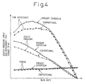
- Fig. 4 is a graph of test results and illustrates the fan efficiency, static pressure and drive torque of the fan for the blow rate.
- the axial fan according to this embodiment exhibits both improved static pressure and improved fan efficiency using the same torque as that of the axial fan of the prior art.
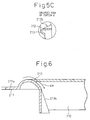
- a skirt portion 213b extends from the curved surface 213 so as to be continuous to the pressure surface side of the blade 212 and expands toward the outer peripheral side, the skirt portion 213b being formed from the front edge of the blade 212 toward the rear edge side thereof.
- the axial fan for vehicles of the invention is adapted to cooling the radiator 100.
- the invention is not limited thereto only but can be adapted to the blowers for the condensers and for other heat exchangers.
- the air is permitted to easily flow from the side of the axial end surface 211a toward the root side of each blade 212, suppressing stalling on the root side of the blades 212. Therefore, the effect of the boss 211 (flow rate of the air from the side of the axial end surface 211a toward the root side of the blades 212) decreases as the diameter of the boss 211 decreases with respect to the outer diameter D of the axial fan 210.
- the invention exhibits its effect more conspicuously for the axial fans having a large ratio (d/D) of the diameter of the boss 211 to the outer diameter D of the axial fan 210. According to a study by the present inventors, it has been confirmed that the invention is particularly effective for axial fans having ratios d/D of not smaller than 0.35.
Landscapes
- Engineering & Computer Science (AREA)
- Mechanical Engineering (AREA)
- General Engineering & Computer Science (AREA)
- Physics & Mathematics (AREA)
- Thermal Sciences (AREA)
- Structures Of Non-Positive Displacement Pumps (AREA)
Abstract
Description
Claims (10)
- An axial fan, for vehicles, having a plurality of blades radially extending from a boss to blow the air to a heat exchanger mounted on the vehicle, wherein the axial end surface of the boss on the negative pressure side of the blades is so constituted that the air flows toward the root side of each blade from the side of the axial end surface.
- An axial fan for vehicles according to claim 1, wherein the root side of each said blade is continuous to said axial end surface through smoothly curved surfaces.
- An axial fan for vehicles according to claim 2, wherein the curved surface is so formed that the contour line of the curved surface describes a streamline shape as viewed from the axial direction of the boss.
- An axial fan for vehicles according to claim 2, wherein a skirt potion extends from the curved surface so as to be continuous with the pressure surface side of the blade and expands toward the outer peripheral side, the skirt portion being formed from the front edge of the blade toward the rear edge side thereof.
- An axial fan for vehicles according to claim 1, wherein said boss and said blades are integrally molded together using a resin.
- An axial fan, for vehicles, having a plurality of blades radially extending from a boss to blow the air to a heat exchanger mounted on the vehicle, wherein the front edges of the blades are deviated toward the upstream side in the air stream beyond the axial end surface at the axial end of the boss, as viewed from a direction at right angles to the axial direction of the boss.
- An axial fan for vehicles according to claim 6, wherein the root side of said blades is continuous with said axial end surface through smoothly curved surfaces.
- An axial fan for vehicles according to claim 7, wherein the curved surface is so formed that the contour line of the curved surface describes a streamline shape, as viewed from the axial direction of said boss.
- An axial fan for vehicles according to claim 7, wherein a skirt portion extends from the curved surface so as to be continuous to the pressure surface side of the blade and expands toward the outer peripheral side, said skirt portion being formed from the front edge of said blade toward the rear edge side thereof.
- An axial fan for vehicles according to claim 6, wherein said boss and said blades are integrally molded together using a resin.
Applications Claiming Priority (3)
| Application Number | Priority Date | Filing Date | Title |
|---|---|---|---|
| JP2001031339 | 2001-02-07 | ||
| JP2001031339 | 2001-02-07 | ||
| PCT/JP2002/001048 WO2002063172A1 (en) | 2001-02-07 | 2002-02-07 | Axial fan for vehicle |
Publications (3)
| Publication Number | Publication Date |
|---|---|
| EP1359327A1 true EP1359327A1 (en) | 2003-11-05 |
| EP1359327A4 EP1359327A4 (en) | 2004-12-15 |
| EP1359327B1 EP1359327B1 (en) | 2007-05-23 |
Family
ID=18895436
Family Applications (1)
| Application Number | Title | Priority Date | Filing Date |
|---|---|---|---|
| EP02711387A Expired - Lifetime EP1359327B1 (en) | 2001-02-07 | 2002-02-07 | Axial fan for vehicle |
Country Status (5)
| Country | Link |
|---|---|
| US (1) | US6659724B2 (en) |
| EP (1) | EP1359327B1 (en) |
| BR (1) | BR0203998B1 (en) |
| DE (1) | DE60220248T2 (en) |
| WO (1) | WO2002063172A1 (en) |
Cited By (1)
| Publication number | Priority date | Publication date | Assignee | Title |
|---|---|---|---|---|
| CN102312858A (en) * | 2011-08-25 | 2012-01-11 | 张家港市东丰特种风机有限公司 | Impeller of axial-flow type heated-air circulation fan |
Families Citing this family (18)
| Publication number | Priority date | Publication date | Assignee | Title |
|---|---|---|---|---|
| JP2004169680A (en) * | 2002-11-18 | 2004-06-17 | Taida Electronic Ind Co Ltd | Blade structure and heat dissipation device using the same |
| US7063125B2 (en) * | 2003-09-10 | 2006-06-20 | Borgwarner Inc. | Fan penetration feature for in-vehicle testing |
| TWI233469B (en) * | 2004-02-03 | 2005-06-01 | Delta Electronics Inc | Fan assembly and impeller thereof |
| CN100424360C (en) * | 2004-02-11 | 2008-10-08 | 台达电子工业股份有限公司 | Fan and fan blade assembly thereof |
| ITBO20040468A1 (en) * | 2004-07-23 | 2004-10-23 | Spal Srl | AXIAL FAN WITH INCREASED FLOW |
| US20060270503A1 (en) * | 2005-05-27 | 2006-11-30 | Takanori Suzuki | Cooling system for continuous variable transmission of vehicle |
| DE102007021604A1 (en) * | 2006-05-09 | 2007-11-15 | Denso Corp., Kariya | fan |
| KR101565294B1 (en) * | 2008-07-31 | 2015-11-04 | 삼성전자 주식회사 | Axial flow fan |
| IT1396350B1 (en) | 2009-10-26 | 2012-11-19 | Spal Automotive Srl | AXIAL FAN |
| DE102010042325A1 (en) * | 2010-10-12 | 2012-04-12 | Behr Gmbh & Co. Kg | Fan with fan blades |
| BRMU9100274U2 (en) * | 2011-02-09 | 2013-05-07 | Jose Roberto Alves | reversible fan for cooling and radiator cleaning |
| US9580137B2 (en) | 2014-04-17 | 2017-02-28 | Thomas S. Felker | Dual powered propulsion system |
| US10569827B2 (en) | 2014-04-17 | 2020-02-25 | Thomas S. Felker | Bicycle dual power turning track, rack, pinion, and one-way bearing propulsion system |
| KR101637745B1 (en) * | 2014-11-25 | 2016-07-07 | 현대자동차주식회사 | Radiator having air guide for preventing heat damage in bus |
| US10569129B2 (en) | 2016-04-15 | 2020-02-25 | Thomas S. Felker | Tri-power exercising device |
| US12268931B2 (en) | 2016-04-15 | 2025-04-08 | Thomas S. Felker | Exercise system |
| USD860427S1 (en) | 2017-09-18 | 2019-09-17 | Horton, Inc. | Ring fan |
| WO2020028010A1 (en) | 2018-08-02 | 2020-02-06 | Horton, Inc. | Low solidity vehicle cooling fan |
Family Cites Families (15)
| Publication number | Priority date | Publication date | Assignee | Title |
|---|---|---|---|---|
| US1473066A (en) * | 1922-03-20 | 1923-11-06 | Merritt R Wells | Fan for automobile radiators or the like |
| US2238749A (en) * | 1939-01-30 | 1941-04-15 | Clarence B Swift | Fan blade |
| DE2062765A1 (en) * | 1970-12-19 | 1972-07-06 | Daimler-Benz AG, 7000 "Stuttgart | Device for cooling motor vehicle internal combustion engines |
| US4671739A (en) * | 1980-07-11 | 1987-06-09 | Robert W. Read | One piece molded fan |
| JPS5783696A (en) * | 1980-11-14 | 1982-05-25 | Nippon Denso Co Ltd | Fan |
| JPS5866000A (en) * | 1981-10-12 | 1983-04-19 | Nissan Motor Co Ltd | Slant flow fan |
| JPS6073000A (en) | 1983-09-29 | 1985-04-25 | コルゲ−ト・パ−モリブ・カンパニ− | Rod form detergent and continuous extrusion |
| JPS6073000U (en) * | 1983-10-25 | 1985-05-22 | ダイキン工業株式会社 | propeller fan |
| JPS60156998A (en) * | 1984-01-26 | 1985-08-17 | Daikin Ind Ltd | propeller fan |
| US5066196A (en) * | 1988-04-21 | 1991-11-19 | Usui Kokusai Sangyo Kabushiki Kaisha | Engine-cooling fan made of synthetic resin |
| JP2659440B2 (en) | 1989-09-25 | 1997-09-30 | 日立マクセル株式会社 | Information card sealing method |
| JP2540439Y2 (en) * | 1990-02-27 | 1997-07-02 | 日本飛行機株式会社 | Axial blower |
| JP3110199B2 (en) | 1993-04-06 | 2000-11-20 | 株式会社日立製作所 | Continuous hot metal plating equipment |
| JP2987133B2 (en) * | 1997-04-25 | 1999-12-06 | 日本電産コパル株式会社 | Axial fan and method for manufacturing blade of axial fan and mold for manufacturing blade of axial fan |
| IT1303113B1 (en) * | 1998-10-08 | 2000-10-30 | Gate Spa | AXIAL FAN, IN PARTICULAR FOR THE COOLING OF A HEAT EXCHANGER IN A VEHICLE. |
-
2002
- 2002-02-07 WO PCT/JP2002/001048 patent/WO2002063172A1/en not_active Ceased
- 2002-02-07 EP EP02711387A patent/EP1359327B1/en not_active Expired - Lifetime
- 2002-02-07 BR BRPI0203998-2A patent/BR0203998B1/en not_active IP Right Cessation
- 2002-02-07 DE DE60220248T patent/DE60220248T2/en not_active Expired - Lifetime
- 2002-10-07 US US10/266,151 patent/US6659724B2/en not_active Expired - Lifetime
Cited By (2)
| Publication number | Priority date | Publication date | Assignee | Title |
|---|---|---|---|---|
| CN102312858A (en) * | 2011-08-25 | 2012-01-11 | 张家港市东丰特种风机有限公司 | Impeller of axial-flow type heated-air circulation fan |
| CN102312858B (en) * | 2011-08-25 | 2013-03-20 | 张家港市东丰特种风机有限公司 | Impeller of axial-flow type heated-air circulation fan |
Also Published As
| Publication number | Publication date |
|---|---|
| US6659724B2 (en) | 2003-12-09 |
| EP1359327A4 (en) | 2004-12-15 |
| EP1359327B1 (en) | 2007-05-23 |
| DE60220248T2 (en) | 2008-01-17 |
| DE60220248D1 (en) | 2007-07-05 |
| BR0203998B1 (en) | 2010-11-16 |
| US20030031561A1 (en) | 2003-02-13 |
| WO2002063172A1 (en) | 2002-08-15 |
| BR0203998A (en) | 2003-02-11 |
Similar Documents
| Publication | Publication Date | Title |
|---|---|---|
| US6659724B2 (en) | Axial fan for vehicles | |
| US6863496B2 (en) | Fan and shroud assembly | |
| JP4973249B2 (en) | Multi-wing fan | |
| KR100548036B1 (en) | Axial fan shroud assembly with guide vane for axial fan and its guide vane | |
| US8512004B2 (en) | Propeller fan | |
| EP2902639B1 (en) | Propeller fan and air conditioner equipped with same | |
| US7121807B2 (en) | Axial-flow fan | |
| US20090126916A1 (en) | Protecting structure of heat exchanger for motor vehicle | |
| US10052931B2 (en) | Outdoor cooling unit in vehicle air-conditioning apparatus | |
| KR20000047976A (en) | Axial flow fan | |
| JP2006125390A (en) | Blower impeller and air conditioner using the same | |
| JP5145188B2 (en) | Multiblade centrifugal fan and air conditioner using the same | |
| JP4618077B2 (en) | Cooling fan and blower | |
| JP4120228B2 (en) | Axial flow fan for vehicles | |
| US20110150665A1 (en) | Fan assembly | |
| JP6224952B2 (en) | Blower | |
| JPH0539930A (en) | Air conditioner | |
| CN106062378A (en) | air supply device | |
| CN113454405B (en) | Indoor unit of air conditioner and air conditioner | |
| JP4000794B2 (en) | Axial fan | |
| JP2006226200A (en) | Engine cooling device | |
| KR20100041127A (en) | Fan and shroud assemble | |
| US20090114366A1 (en) | Heat exchanger for vehicle | |
| KR101187223B1 (en) | Axial Flow Fan | |
| JP2023139347A (en) | air conditioner |
Legal Events
| Date | Code | Title | Description |
|---|---|---|---|
| PUAI | Public reference made under article 153(3) epc to a published international application that has entered the european phase |
Free format text: ORIGINAL CODE: 0009012 |
|
| 17P | Request for examination filed |
Effective date: 20021007 |
|
| AK | Designated contracting states |
Kind code of ref document: A1 Designated state(s): AT BE CH CY DE DK ES FI FR GB GR IE IT LI LU MC NL PT SE TR |
|
| A4 | Supplementary search report drawn up and despatched |
Effective date: 20041029 |
|
| RIC1 | Information provided on ipc code assigned before grant |
Ipc: 7F 04D 29/58 B Ipc: 7F 04D 29/38 A Ipc: 7F 01P 5/02 B |
|
| 17Q | First examination report despatched |
Effective date: 20050214 |
|
| GRAP | Despatch of communication of intention to grant a patent |
Free format text: ORIGINAL CODE: EPIDOSNIGR1 |
|
| RBV | Designated contracting states (corrected) |
Designated state(s): DE FR |
|
| RIN1 | Information on inventor provided before grant (corrected) |
Inventor name: TAKEUCHI, KAZUHIRO,C/O DENSO CORPORATION Inventor name: ODA, SHINICHIC/O DENSO CORPORATION Inventor name: MURAI, ISAO,C/O DENSO CORPORATION |
|
| GRAS | Grant fee paid |
Free format text: ORIGINAL CODE: EPIDOSNIGR3 |
|
| GRAA | (expected) grant |
Free format text: ORIGINAL CODE: 0009210 |
|
| AK | Designated contracting states |
Kind code of ref document: B1 Designated state(s): DE FR |
|
| REF | Corresponds to: |
Ref document number: 60220248 Country of ref document: DE Date of ref document: 20070705 Kind code of ref document: P |
|
| ET | Fr: translation filed | ||
| PLBE | No opposition filed within time limit |
Free format text: ORIGINAL CODE: 0009261 |
|
| STAA | Information on the status of an ep patent application or granted ep patent |
Free format text: STATUS: NO OPPOSITION FILED WITHIN TIME LIMIT |
|
| 26N | No opposition filed |
Effective date: 20080226 |
|
| REG | Reference to a national code |
Ref country code: FR Ref legal event code: PLFP Year of fee payment: 15 |
|
| REG | Reference to a national code |
Ref country code: FR Ref legal event code: PLFP Year of fee payment: 16 |
|
| REG | Reference to a national code |
Ref country code: FR Ref legal event code: PLFP Year of fee payment: 17 |
|
| PGFP | Annual fee paid to national office [announced via postgrant information from national office to epo] |
Ref country code: FR Payment date: 20210224 Year of fee payment: 20 |
|
| PGFP | Annual fee paid to national office [announced via postgrant information from national office to epo] |
Ref country code: DE Payment date: 20210217 Year of fee payment: 20 |