EP1359303A2 - Variable stroke engine - Google Patents
Variable stroke engine Download PDFInfo
- Publication number
- EP1359303A2 EP1359303A2 EP03008294A EP03008294A EP1359303A2 EP 1359303 A2 EP1359303 A2 EP 1359303A2 EP 03008294 A EP03008294 A EP 03008294A EP 03008294 A EP03008294 A EP 03008294A EP 1359303 A2 EP1359303 A2 EP 1359303A2
- Authority
- EP
- European Patent Office
- Prior art keywords
- rod
- sub
- stroke engine
- variable stroke
- engine according
- Prior art date
- Legal status (The legal status is an assumption and is not a legal conclusion. Google has not performed a legal analysis and makes no representation as to the accuracy of the status listed.)
- Granted
Links
Images


Classifications
-
- F—MECHANICAL ENGINEERING; LIGHTING; HEATING; WEAPONS; BLASTING
- F02—COMBUSTION ENGINES; HOT-GAS OR COMBUSTION-PRODUCT ENGINE PLANTS
- F02B—INTERNAL-COMBUSTION PISTON ENGINES; COMBUSTION ENGINES IN GENERAL
- F02B75/00—Other engines
- F02B75/04—Engines with variable distances between pistons at top dead-centre positions and cylinder heads
- F02B75/048—Engines with variable distances between pistons at top dead-centre positions and cylinder heads by means of a variable crank stroke length
-
- F—MECHANICAL ENGINEERING; LIGHTING; HEATING; WEAPONS; BLASTING
- F02—COMBUSTION ENGINES; HOT-GAS OR COMBUSTION-PRODUCT ENGINE PLANTS
- F02B—INTERNAL-COMBUSTION PISTON ENGINES; COMBUSTION ENGINES IN GENERAL
- F02B75/00—Other engines
- F02B75/04—Engines with variable distances between pistons at top dead-centre positions and cylinder heads
-
- F—MECHANICAL ENGINEERING; LIGHTING; HEATING; WEAPONS; BLASTING
- F01—MACHINES OR ENGINES IN GENERAL; ENGINE PLANTS IN GENERAL; STEAM ENGINES
- F01L—CYCLICALLY OPERATING VALVES FOR MACHINES OR ENGINES
- F01L1/00—Valve-gear or valve arrangements, e.g. lift-valve gear
- F01L1/02—Valve drive
- F01L1/024—Belt drive
-
- F—MECHANICAL ENGINEERING; LIGHTING; HEATING; WEAPONS; BLASTING
- F02—COMBUSTION ENGINES; HOT-GAS OR COMBUSTION-PRODUCT ENGINE PLANTS
- F02B—INTERNAL-COMBUSTION PISTON ENGINES; COMBUSTION ENGINES IN GENERAL
- F02B41/00—Engines characterised by special means for improving conversion of heat or pressure energy into mechanical power
- F02B41/02—Engines with prolonged expansion
- F02B41/04—Engines with prolonged expansion in main cylinders
-
- F—MECHANICAL ENGINEERING; LIGHTING; HEATING; WEAPONS; BLASTING
- F02—COMBUSTION ENGINES; HOT-GAS OR COMBUSTION-PRODUCT ENGINE PLANTS
- F02B—INTERNAL-COMBUSTION PISTON ENGINES; COMBUSTION ENGINES IN GENERAL
- F02B75/00—Other engines
- F02B75/16—Engines characterised by number of cylinders, e.g. single-cylinder engines
-
- F—MECHANICAL ENGINEERING; LIGHTING; HEATING; WEAPONS; BLASTING
- F02—COMBUSTION ENGINES; HOT-GAS OR COMBUSTION-PRODUCT ENGINE PLANTS
- F02D—CONTROLLING COMBUSTION ENGINES
- F02D15/00—Varying compression ratio
- F02D15/02—Varying compression ratio by alteration or displacement of piston stroke
-
- F—MECHANICAL ENGINEERING; LIGHTING; HEATING; WEAPONS; BLASTING
- F02—COMBUSTION ENGINES; HOT-GAS OR COMBUSTION-PRODUCT ENGINE PLANTS
- F02B—INTERNAL-COMBUSTION PISTON ENGINES; COMBUSTION ENGINES IN GENERAL
- F02B75/00—Other engines
- F02B75/02—Engines characterised by their cycles, e.g. six-stroke
- F02B2075/022—Engines characterised by their cycles, e.g. six-stroke having less than six strokes per cycle
- F02B2075/027—Engines characterised by their cycles, e.g. six-stroke having less than six strokes per cycle four
-
- F—MECHANICAL ENGINEERING; LIGHTING; HEATING; WEAPONS; BLASTING
- F02—COMBUSTION ENGINES; HOT-GAS OR COMBUSTION-PRODUCT ENGINE PLANTS
- F02B—INTERNAL-COMBUSTION PISTON ENGINES; COMBUSTION ENGINES IN GENERAL
- F02B2275/00—Other engines, components or details, not provided for in other groups of this subclass
- F02B2275/34—Lateral camshaft position
Definitions
- the present invention relates to a variable stroke engine having a connecting rod with one end thereof connected to a piston via a piston pin, a sub-rod connected to a crankshaft via a crankpin and to the other end of the connecting rod, and a control rod with one end thereof connected to the sub-rod at a position distal from the position where the connecting rod is connected.
- the present invention relates to a variable stroke engine also having an eccentric shaft connected to the other end of the control rod, wherein the eccentric shaft is provided at a position eccentric relative to a rotating shaft to which power is transmitted from the crankshaft at a reduction ratio of 1/2.
- variable stroke engine such as, for example, the engine disclosed in U.S. Patent No. 4,517,931 to Nelson.
- crankshaft In the case of a DOHC or SOHC variable stroke engine, rotational power is generally transmitted from the crankshaft to a camshaft supported on a cylinder head at a reduction ratio of 1/2 using a timing belt and the like.
- a camshaft In the case of an OHV variable stroke engine, a camshaft is generally provided to which power is transmitted from the crankshaft at a reduction ratio of 1/2 by a reduction gear, in addition to a rotating shaft, to which power is transmitted from the crankshaft at a reduction ratio of 1/2.
- a variable stroke engine in accordance with a first aspect of the present invention, includes a connecting rod with one end thereof connected to a piston via a piston pin, a sub-rod connected to a crankshaft via a crankpin and to the other end of the connecting rod, a control rod with one end thereof connected to the sub-rod at a position distal from the position where the connecting rod is connected, and an eccentric shaft that is connected to the other end of the control rod.
- the eccentric shaft is provided at a position eccentric relative to a rotating shaft to which power is transmitted from the crankshaft at a reduction ratio of 1 ⁇ 2.
- a cam which forms a part of a valve operating mechanism, is provided on the rotating shaft.
- the cam is provided on the rotating shaft having the eccentric shaft, it is unnecessary to use a camshaft and rotating shaft. As a result, the total number of structural components is reduced. Further, space is not required to be provided to arrange the camshaft, thereby reducing the overall dimensions of the engine. Furthermore, since a dedicated camshaft is not needed, a power transmission mechanism is not required to be positioned between the crankshaft and the dedicated camshaft, thereby reducing the amount of mechanical noise and friction loss.
- a variable stroke engine in addition to the arrangement of the first aspect, includes an intake cam, an exhaust cam, and an eccentric shaft disposed between the intake and exhaust cams all of which are integrally provided on the rotating shaft.
- the eccentric shaft has a diameter that covers the entire shape of one of the intake and exhaust cams when viewed from a direction along the axis of the rotating shaft.
- the eccentric shaft can be provided on the rotating shaft without using a crank arrangement for the rotating shaft, the machining precision of the eccentric shaft and the intake and exhaust cams is improved, and the rotating shaft is formed with relatively low weight and increased rigidity.
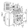
- Fig. 1 is a front view of an engine according to a preferred embodiment of the present invention
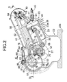
- Fig. 2 is a longitudinal cross-sectional view of the engine shown in Fig. 1, taken along line 2-2 in Fig. 3 when viewed from the same direction as in Fig. 1;
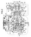
- Fig. 3 is a cross-sectional view of the engine shown in Fig. 1, taken along line 3-3 in Fig. 2;
- Fig. 4 is a magnified cross-sectional view of the engine shown in Fig. 1, taken along line 4-4 in Fig. 2;
- Fig. 5 is a magnified cross-sectional view of the engine shown in Fig. 1, taken along line 5-5 in Fig. 3.
- the illustrated engine is an air-cooled single cylinder engine used in, for example, work equipment.
- An engine main body 21 is formed from a crankcase 22, a cylinder block 23, and a cylinder head 24 joined to the head of the cylinder block 23.
- the cylinder block 23 is inclined slightly upward and projects from a side face of the crankcase 22.
- a plurality of air-cooling fins 23a, 24a are provided on the outer side faces of the cylinder block 23 and the cylinder head 24, respectively.
- the crankcase 22 is mounted on an engine bed of various types of work equipment via a mounting face 22a on a lower face of the crankcase 22.
- the crankcase 22 is formed from a case main body 25 and a side cover 26 joined to an open end of the case main body 25.
- the case main body 25 is integrally mold-cast with the cylinder block 23.
- Opposite ends of a crankshaft 27 are rotatably supported in the case main body 25 and the side cover 26 via ball bearings 28, 29 and oil seals 30, 31.
- One end of the crankshaft 27 projects out of the side cover 26 and serves as an output shaft portion 27a.
- the other end of the crankshaft 27 projects out of the case main body 25 and serves as an auxiliary equipment attachment shaft portion 27b.
- a flywheel 32 is fixed to the auxiliary equipment attachment shaft portion 27b.
- a cooling fan 35 is rigidly attached by a screw 36 to the outside surface of the flywheel 32 and supplies cooling air to each part of the engine main body 21 and a carburetor 34.
- a recoil type engine starter 37 is disposed outside the cooling fan 35.
- a piston 38 is slidably fitted in a cylinder bore 39 formed in the cylinder block 23.
- a combustion chamber 40 is formed between the cylinder block 23 and the cylinder head 24 which the top of the piston 38 faces.
- An intake port 41 and an exhaust port 42 are formed in the cylinder head 24 and communicate with the combustion chamber 40.
- An intake valve 43 and an exhaust valve 44 are arranged in the cylinder head 24.
- the intake valve 43 opens and closes communication between the intake port 41 and the combustion chamber 40.
- the exhaust valve 44 opens and closes communication between the exhaust port 42 and the combustion chamber 40.
- a spark plug 45 is screwed into the cylinder head 24 and has electrodes facing the combustion chamber 40.
- the carburetor 34 is connected to an upper part of the cylinder head 24.
- the downstream end of an intake passage 46 of the carburetor 34 communicates with the intake port 41.
- An intake pipe 47 communicating with the upstream end of the intake passage 46 is connected to the carburetor 34.
- the intake pipe 47 is also connected to an air cleaner (not illustrated).
- An exhaust pipe 48 communicating with the exhaust port 42 is connected to an upper part of the cylinder head 24.
- the exhaust pipe 48 is also connected to an exhaust muffler 49.
- a fuel tank 51 which is supported by a bracket 50 projecting from the crankcase 22, is disposed above the crankcase 22.
- a drive gear 52 is fixedly provided on the crankshaft 27 near the side cover 26 of the crankcase 22.
- a driven gear 53 that meshes with the drive gear 52 is fixedly attached to a rotating shaft 54 having an axis parallel to the crankshaft 27.
- Opposite ends of the rotating shaft 54 are rotatably carried on the crankcase 22, which includes the case main body 25 and the side cover 26, via ball bearings 55, 56. Rotational power from the crankshaft 27 is transmitted to the rotating shaft 54 at a reduction ratio of 1/2 via the meshed drive gear 52 and the driven gear 53.
- a valve operating mechanism 66 which opens and closes the intake valve 43 and the exhaust valve 44, includes an intake cam 57, an exhaust cam 58, lifters 59, 60, pushrods 62, 63, and rocker arms 64, 65, which are provided between the pushrods 62, 63 and the intake and exhaust valves 43, 44.
- the intake cam 57 and the exhaust cam 58 are rotated by the crankshaft 27 at a reduction ratio of 1/2.
- the lifters 59, 60 are in sliding contact with the cams 57, 58.
- the pushrods 62, 63 are pushed by the lifters 59, 60.
- the intake cam 57 and the exhaust cam 58 which correspond to the intake valve 43 and the exhaust valve 44, respectively, are provided on the rotating shaft 54.
- the lifters 59, 60 are operably supported in the cylinder block 23 and are in sliding contact with the intake cam 57 and the exhaust cam 58.
- An operating chamber 61 is formed in the cylinder block 23 and the cylinder head 24. Upper parts of the lifters 59, 60 project into a lower part of the operating chamber 61.
- the lower ends of the pushrods 62, 63 disposed within the operating chamber 61 abut against the lifters 59, 60.
- Rocker arms 64, 65 are rockably carried in the cylinder head 24.
- each rocker arm 64 and 65 abuts against the upper end of a corresponding one of the intake valve 43 and the exhaust valve 44, which are spring-biased in a valve-closing direction.
- the upper end of each pushrod 62 and 63 abuts against the other end of the corresponding one of the rocker arms 64 and 65.
- valve operating mechanism 66 the pushrods 62, 63 move in the axial direction as the intake cam 57 and the exhaust cam 58 rotate.
- the resulting rocking of the rocker arms 64 and 65 opens and closes the intake valve 43 and the exhaust valve 44.
- an eccentric shaft 67 provided at a position eccentric relative to the rotating shaft 54, the piston 38, and the crankshaft 27 are connected to each other via a link mechanism 68.
- the link mechanism 68 is formed from a connecting rod 70, a sub-rod 72, a control rod 73, and the eccentric shaft 67.
- One end of the connecting rod 70 is connected to the piston 38 via a piston pin 69
- the sub-rod 72 is connected to the crankshaft 27 via a crankpin 71 and to the other end of the connecting rod 70
- one end of the control rod 73 is connected to the sub-rod 72 at a position away from the position where the connecting rod 70 is connected
- the eccentric shaft 67 is connected to the other end of the control rod 73.
- the sub-rod 72 has in its middle portion a semicircular first bearing 74 that is in sliding contact with half of the periphery of the crankpin 71. Integrally provided at opposite ends of the sub-rod 72 are a pair of bifurcated portions 72a, 72b sandwiching the other end of the connecting rod 70 and the one end of the control rod 73, respectively. The remaining half of the periphery of the crankpin 71 is in sliding contact with a semicircular second bearing 75 of a crank cap 76. The crank cap 76 is secured to the sub-rod 72.
- the other end of the connecting rod 70 is inserted into the bifurcated portion 72a at one end of the sub-rod 72 and is swingably connected to the one end of the sub-rod 72 via a connecting rod pin 77.
- Opposite ends of the connecting rod pin 77, which is press-fitted in the other end of the connecting rod 70, are swingably fitted in the bifurcated portion 72a at the one end of the sub-rod 72.
- the one end of the control rod 73 is inserted into the bifurcated portion 72b at the other end of the sub-rod 72 and is swingably connected to the sub-rod 72 via a sub-rod pin 78.
- the sub-rod pin 78 runs relatively swingably through the one end of the control rod 73.
- Opposite ends of the sub-rod pin 78 are swingably supported in the bifurcated portion 72a at the other end of the sub-rod 72.
- the eccentric shaft 67 is integrally formed on the rotating shaft 54 and is positioned between the intake cam 57 and the exhaust cam 58.
- the eccentric shaft 67 has a diameter that covers the entirety of either one of the intake cam 57 and the exhaust cam 58 when viewed from a direction along the axis of the rotating shaft 54.
- a circular shaft hole 79 is provided at the other end of the control rod 73. The eccentric shaft 67 is relatively slidably fitted within the hole 79.
- the link mechanism 68 operates so that the stroke of the piston 38 during expansion is larger than the stroke during compression. Accordingly, a greater amount of expansion work is carried out with the same amount of intake mixture, thereby enhancing the cycle thermal efficiency.
- a tube-shaped breather chamber 80 is formed in the engine main body 21 above the eccentric shaft 67 of the rotating shaft 54. That is, integrally provided on the case main body 25 of the crankcase 22 of the engine main body 21 is a rectangular breather housing 81 which projects upward. The breather housing 81 and a cover plate 82 secured thereto, wherein the cover plate 82 blocks an opening at the outer end of the breather housing 81, form the breather chamber 80.
- the breather chamber 80 communicates with the interior of the crankcase 22 via an inlet 83 provided in the case main body 25 in a section corresponding to the eccentric shaft 67.
- a baffle plate 84 supported on the cover plate 82 forms a labyrinth within the breather chamber 80.
- Breather gas that has passed through the labyrinth is discharged, for example, through an outlet 85 provided in the breather housing 81, and is guided to an air cleaner via a pipe (not illustrated).
- Oil that is entrained in the breather gas is subjected to gas-liquid separation while passing through the labyrinth.
- the oil that has been separated and collected in a lower part of the breather chamber 80 drops into the interior of the crankcase 22 through an oil supply hole 86 provided in the case main body 25 at a position adjacent to the inlet 83 so that the oil drops onto the eccentric shaft 67.
- the intake and exhaust cams 57, 58 forming a part of the valve operating mechanism 66 are provided on the rotating shaft 54 having the eccentric shaft 67. Power from the crankshaft 27 is transmitted to the rotating shaft 54 at a reduction ratio of 1/2. Therefore, it is unnecessary to use a camshaft in addition to the rotating shaft 54, thus reducing the number of structural components, and space is not required to be provided to arrange the camshaft, thereby reducing the overall dimensions of the engine. Since a dedicated camshaft is not needed, a power transfer mechanism between the crankshaft 27 and the dedicated camshaft is not required, thereby reducing the mechanical noise and the friction loss.
- Integrally provided on the rotating shaft 54 is the intake cam 57, the exhaust cam 58, and the eccentric shaft 67 disposed between the intake and exhaust cams 57 and 58.
- the eccentric shaft 67 has a diameter that covers the entire shape of either one of the intake cam 57 and the exhaust cam 58 when viewed from a direction along the axis of the rotating shaft 54.
- the eccentric shaft 67 can be provided on the rotating shaft 54 without using a crank arrangement for the rotating shaft 54, the machining precision of the eccentric shaft 67 and the intake and exhaust cams 57 and 58 is improved, and the rotating shaft is formed with relatively low weight and increased rigidity.
- the oil separated from the breather gas within the breather chamber 80 drops onto the eccentric shaft 67, so that lubrication can be provided between the eccentric shaft 67 and the control rod 73 while eliminating the need for a lubricating device exclusively used for the eccentric shaft 67, thereby reducing the overall dimensions and the weight of the engine.
- a variable stroke engine includes a connecting rod having one end thereof connected to a piston via a piston pin.
- a sub-rod is connected to a crankshaft via a crankpin and to the other end of the connecting rod.
- a control rod has one end thereof connected to the sub-rod at a position distal from the position where the sub-rod is connected to the connecting rod.
- An eccentric shaft is connected to the other end of the control rod. The eccentric shaft is provided at a position eccentric relative to a rotating shaft to which power is transmitted from the crankshaft at a reduction ratio of 1 ⁇ 2.
- Intake and exhaust cams form a part of a valve operating mechanism and are provided on the rotating shaft.
Landscapes
- Engineering & Computer Science (AREA)
- Mechanical Engineering (AREA)
- General Engineering & Computer Science (AREA)
- Chemical & Material Sciences (AREA)
- Combustion & Propulsion (AREA)
- Output Control And Ontrol Of Special Type Engine (AREA)
- Valve-Gear Or Valve Arrangements (AREA)
- Shafts, Cranks, Connecting Bars, And Related Bearings (AREA)
- Transmission Devices (AREA)
- Valve Device For Special Equipments (AREA)
Abstract
Description
A variable stroke engine includes a connecting rod having one end thereof connected to a piston via a piston pin. A sub-rod is connected to a crankshaft via a crankpin and to the other end of the connecting rod. A control rod has one end thereof connected to the sub-rod at a position distal from the position where the sub-rod is connected to the connecting rod. An eccentric shaft is connected to the other end of the control rod. The eccentric shaft is provided at a position eccentric relative to a rotating shaft to which power is transmitted from the crankshaft at a reduction ratio of ½. Intake and exhaust cams form a part of a valve operating mechanism and are provided on the rotating shaft.
Claims (15)
- A variable stroke engine comprising:wherein at least one of an intake cam and an exhaust cam of a valve operating mechanism is provided on the rotating shaft.a connecting rod having one end connected to a piston via a piston pin;a sub-rod connected to a crankshaft via a crankpin and connected to the other end of the connecting rod;a control rod connected at one end to the sub-rod at a position distal from a position where the sub-rod is connected to the connecting rod; andan eccentric shaft connected to the other end of the control rod, wherein the eccentric shaft is provided at a position eccentric relative to a rotating shaft to which power is transmitted from the crankshaft at a reduction ratio of ½,
- The variable stroke engine according to Claim 1, wherein the intake cam, the exhaust cam, and the eccentric shaft, which is disposed between the intake and exhaust cams, are integrally provided on the rotating shaft, and wherein the eccentric shaft has a diameter that covers the entirety of either one of the intake and exhaust cams when viewed from a direction along an axis of the rotating shaft.
- The variable stroke engine according to Claim 1, wherein the valve operating mechanism includes the intake cam, the exhaust cam, first and second lifters, first and second pushrods, and first and second rocker arms, wherein the first and second rocker arms are provided between the intake cam and the first pushrod and the exhaust cam and the second pushrod, respectively.
- The variable stroke engine according to Claim 3, wherein the intake and exhaust cams are rotated by the crankshaft at a reduction ratio of ½.
- The variable stroke engine according to Claim 3, wherein the first and second lifters are in sliding contact with the intake and exhaust cams, respectively, and push the first and second pushrods, respectively.
- The variable stroke engine according to Claim 3, wherein the first and second pushrods move in an axial direction orthogonal relative to an axis of the rotating shaft as the intake and exhaust cams rotate.
- The variable stroke engine according to Claim 1, wherein a middle portion of the sub-rod includes a semicircular bearing in sliding contact with a first periphery half of the crankpin connecting the sub-rod to the crankshaft.
- The variable stroke engine according to Claim 7, wherein a second periphery half of the crankpin is in sliding contact with a semicircular bearing of a crank cap secured to the sub-rod.
- The variable stroke engine according to Claim 1, wherein opposite ends of the sub-rod include first and second bifurcated portions, respectively,
wherein one end of the sub-rod swingably secures the other end of the connecting rod and the other end of the sub-rod swingably secures the one end of the control rod. - The variable stroke engine according to Claim 9, wherein a connecting rod pin swingably connects the other end of the connecting rod to the one end of the sub-rod and a sub-rod pin swingably connects the one end of the control rod to the other end of the sub-rod.
- The variable stroke engine according to Claim 1, wherein an expansion stroke of the piston is larger than a compression stroke of the piston.
- The variable stroke engine according to Claim 1, further comprising a breather chamber provided above the eccentric shaft of the rotating shaft.
- The variable stroke engine according to Claim 12, wherein the breather chamber includes a breather housing and a cover plate secured thereto, wherein the cover plate blocks an opening of the breather housing.
- The variable stroke engine according to Claim 13, wherein a baffle plate is supported on the cover plate and separates oil therein from a breather gas that passes through the baffle plate.
- The variable stroke engine according to Claim 14, wherein the separated oil is directed onto the eccentric shaft.
Applications Claiming Priority (2)
| Application Number | Priority Date | Filing Date | Title |
|---|---|---|---|
| JP2002114271A JP2003314211A (en) | 2002-04-17 | 2002-04-17 | Variable stroke engine |
| JP2002114271 | 2002-04-17 |
Publications (3)
| Publication Number | Publication Date |
|---|---|
| EP1359303A2 true EP1359303A2 (en) | 2003-11-05 |
| EP1359303A3 EP1359303A3 (en) | 2004-01-28 |
| EP1359303B1 EP1359303B1 (en) | 2006-03-08 |
Family
ID=29207652
Family Applications (1)
| Application Number | Title | Priority Date | Filing Date |
|---|---|---|---|
| EP03008294A Expired - Lifetime EP1359303B1 (en) | 2002-04-17 | 2003-04-09 | Variable stroke engine |
Country Status (12)
| Country | Link |
|---|---|
| US (1) | US7185615B2 (en) |
| EP (1) | EP1359303B1 (en) |
| JP (1) | JP2003314211A (en) |
| KR (1) | KR100576964B1 (en) |
| CN (2) | CN1267631C (en) |
| AU (1) | AU2003203684B2 (en) |
| BR (1) | BR0300938B1 (en) |
| CA (1) | CA2425751C (en) |
| DE (2) | DE60303834T8 (en) |
| ES (1) | ES2260536T3 (en) |
| MX (1) | MXPA03003391A (en) |
| TW (1) | TW576891B (en) |
Cited By (5)
| Publication number | Priority date | Publication date | Assignee | Title |
|---|---|---|---|---|
| EP1801387A1 (en) * | 2005-12-20 | 2007-06-27 | Nissan Motor Company Limited | Lower link for piston crank mechanism of internal combustion engine |
| EP2123869A1 (en) * | 2008-05-21 | 2009-11-25 | Honda Motor Co., Ltd. | Link type variable stroke engine |
| EP2136049A1 (en) * | 2008-05-20 | 2009-12-23 | Honda Motor Co., Ltd. | Link type variable stroke engine |
| WO2011098104A1 (en) * | 2010-01-14 | 2011-08-18 | Audi Ag | Internal combustion engine having an extended expansion stroke and counterweights on the eccentric shaft |
| US8978616B2 (en) | 2010-07-28 | 2015-03-17 | Audi Ag | Internal combustion engine with multi-joint crank drive and additional masses on articulated connecting rods of the multi-joint crank drive for damping free inertia forces |
Families Citing this family (29)
| Publication number | Priority date | Publication date | Assignee | Title |
|---|---|---|---|---|
| DE102005020270A1 (en) * | 2005-04-30 | 2006-11-09 | Daimlerchrysler Ag | Internal combustion engine with variable compression ratio |
| DE102005029481B4 (en) * | 2005-06-24 | 2008-04-10 | Bran + Luebbe Gmbh | gear pumps |
| JP2007064013A (en) * | 2005-08-29 | 2007-03-15 | Honda Motor Co Ltd | Variable stroke engine |
| TWI308614B (en) * | 2005-08-29 | 2009-04-11 | Honda Motor Co Ltd | Stroke-variable engine |
| DE102005054760A1 (en) * | 2005-11-17 | 2007-05-31 | Daimlerchrysler Ag | Reciprocating internal combustion engine with variable compression ratio |
| JP4631757B2 (en) * | 2006-03-14 | 2011-02-16 | 日産自動車株式会社 | Control device for internal combustion engine |
| JP4983593B2 (en) * | 2007-04-10 | 2012-07-25 | 日産自動車株式会社 | Fuel pump drive unit |
| US7856714B2 (en) * | 2007-10-10 | 2010-12-28 | The Invention Science Fund I, Llc | Method of retrofitting an engine |
| JP5309146B2 (en) | 2007-10-04 | 2013-10-09 | シーレイト リミテッド ライアビリティー カンパニー | Electromagnetic engine |
| US7777357B2 (en) * | 2007-10-05 | 2010-08-17 | The Invention Fund I, LLC | Free piston electromagnetic engine |
| US7622814B2 (en) * | 2007-10-04 | 2009-11-24 | Searete Llc | Electromagnetic engine |
| US7950356B2 (en) * | 2007-10-09 | 2011-05-31 | The Invention Science Fund I, Llc | Opposed piston electromagnetic engine |
| JP4922121B2 (en) * | 2007-10-11 | 2012-04-25 | 本田技研工業株式会社 | Variable stroke engine |
| KR100921806B1 (en) | 2007-11-29 | 2009-10-16 | 현대자동차주식회사 | Variable compression ratio |
| KR101405176B1 (en) | 2008-03-03 | 2014-06-10 | 현대자동차 주식회사 | Variable compression ratio apparatus |
| JP4979631B2 (en) * | 2008-05-13 | 2012-07-18 | 本田技研工業株式会社 | Link-type variable stroke engine |
| JP2009275552A (en) * | 2008-05-13 | 2009-11-26 | Honda Motor Co Ltd | Link type stroke variable engine |
| KR100969385B1 (en) | 2008-07-07 | 2010-07-09 | 현대자동차주식회사 | Variable compression ratio apparatus |
| US7891334B2 (en) * | 2008-07-17 | 2011-02-22 | O'leary Paul W | Engine with variable length connecting rod |
| DE102009006633A1 (en) * | 2009-01-29 | 2010-08-05 | Audi Ag | Internal combustion engine with extended expansion stroke and adjustable compression ratio |
| KR101459428B1 (en) * | 2009-12-02 | 2014-11-10 | 현대자동차 주식회사 | Variable compression ratio device |
| DE102010004593B4 (en) * | 2010-01-14 | 2016-03-10 | Audi Ag | Internal combustion engine with variable compression and one-piece Anlenkpleueln |
| DE102010027351B4 (en) | 2010-07-16 | 2013-06-13 | Audi Ag | Internal combustion engine with extended expansion stroke and torque compensation |
| JP5735240B2 (en) * | 2010-09-06 | 2015-06-17 | 川崎重工業株式会社 | Engine balancer shaft structure |
| CN103306811B (en) * | 2013-07-11 | 2015-06-03 | 姚长水 | Energy-saving reciprocating type variable-stroke engine |
| JP6265161B2 (en) * | 2015-03-30 | 2018-01-24 | トヨタ自動車株式会社 | Variable compression ratio internal combustion engine |
| WO2021016690A1 (en) | 2019-07-28 | 2021-02-04 | Goncalves Pereira Almir | Device for variation of compression ratio |
| US11092090B1 (en) | 2020-09-30 | 2021-08-17 | GM Global Technology Operations LLC | Multilink cranktrains with combined eccentric shaft and camshaft drive system for internal combustion engines |
| CN112501895B (en) * | 2020-11-21 | 2021-11-05 | 苏州美律纺织机械电子有限公司 | Wool removing device for textile machinery |
Family Cites Families (25)
| Publication number | Priority date | Publication date | Assignee | Title |
|---|---|---|---|---|
| US1174801A (en) * | 1915-01-07 | 1916-03-07 | George E Babcock | Variable-stroke internal-combustion engine. |
| US4050435A (en) * | 1975-12-02 | 1977-09-27 | Harold L. Fuller, Jr. | Valve control for cylinder cutout system |
| US4517931A (en) * | 1983-06-30 | 1985-05-21 | Nelson Carl D | Variable stroke engine |
| US4714058A (en) * | 1984-12-10 | 1987-12-22 | Mazda Motor Corporation | Spark-ignited internal combustion engine |
| JPS61149525A (en) * | 1984-12-20 | 1986-07-08 | Mitsuo Okamoto | Double crankshaft type internal combustion engine |
| US4852527A (en) * | 1987-01-28 | 1989-08-01 | General Motors Corporation | Low noise valve train |
| JPH0723531Y2 (en) * | 1988-10-18 | 1995-05-31 | 日産自動車株式会社 | Blow-by gas recirculation system for engines |
| US4926814A (en) * | 1989-07-12 | 1990-05-22 | Tecumseh Products Company | Crankcase breather and lubrication oil system for an internal combustion engine |
| US5230317A (en) * | 1989-11-29 | 1993-07-27 | Yamaha Hatsudoki Kabushiki Kaisha | Single overhead cam multi-valve engine |
| US5415138A (en) * | 1994-02-28 | 1995-05-16 | Brunswick Corporation | Pushrod guide for an overhead valve engine and method of installing the same |
| US5732670A (en) * | 1996-02-13 | 1998-03-31 | Charles R. Mote, Sr. | Geared rocker valve operation for internal combustion reciprocating piston engines |
| US5617834A (en) * | 1996-03-05 | 1997-04-08 | Ford Motor Company | Air-oil separator for a crankcase ventilation system in an internal combustion engine |
| JPH11107734A (en) * | 1997-09-30 | 1999-04-20 | Sanshin Ind Co Ltd | Blow-by gas recirculation device for outboard engine |
| JP2000045714A (en) | 1998-07-28 | 2000-02-15 | Sanshin Ind Co Ltd | Structure of engine cam shaft |
| JP3423649B2 (en) | 1999-09-03 | 2003-07-07 | 本田技研工業株式会社 | Breather chamber structure of internal combustion engine |
| JP2001280112A (en) * | 2000-03-31 | 2001-10-10 | Honda Motor Co Ltd | Gas-liquid separation chamber for outboard engine |
| JP4038959B2 (en) * | 2000-05-09 | 2008-01-30 | 日産自動車株式会社 | Variable compression ratio mechanism of internal combustion engine |
| JP3968967B2 (en) * | 2000-07-07 | 2007-08-29 | 日産自動車株式会社 | Variable compression ratio mechanism of reciprocating internal combustion engine |
| JP4062867B2 (en) | 2000-07-31 | 2008-03-19 | 日産自動車株式会社 | Internal combustion engine with variable compression ratio mechanism |
| JP3861583B2 (en) * | 2000-08-14 | 2006-12-20 | 日産自動車株式会社 | Piston crank mechanism of internal combustion engine |
| US6536393B2 (en) * | 2000-09-11 | 2003-03-25 | Tecumseh Products Company | Mechanical compression and vacuum release |
| AU2002213520A1 (en) * | 2000-09-18 | 2002-03-26 | Jeremy Jason Louw | Smart piston engine |
| JP3726678B2 (en) * | 2000-12-15 | 2005-12-14 | 日産自動車株式会社 | Crank mechanism of a multi-link reciprocating internal combustion engine |
| US6505589B1 (en) * | 2002-02-01 | 2003-01-14 | General Motors Corporation | Single cam three-valve engine overhead valve train |
| EP1347161B1 (en) * | 2002-03-20 | 2007-06-27 | Honda Giken Kogyo Kabushiki Kaisha | Variable compression ratio engine |
-
2002
- 2002-04-17 JP JP2002114271A patent/JP2003314211A/en active Pending
-
2003
- 2003-04-09 ES ES03008294T patent/ES2260536T3/en not_active Expired - Lifetime
- 2003-04-09 DE DE60303834T patent/DE60303834T8/en active Active
- 2003-04-09 DE DE60303834A patent/DE60303834D1/en not_active Expired - Lifetime
- 2003-04-09 EP EP03008294A patent/EP1359303B1/en not_active Expired - Lifetime
- 2003-04-10 TW TW092108256A patent/TW576891B/en not_active IP Right Cessation
- 2003-04-11 US US10/411,392 patent/US7185615B2/en not_active Expired - Fee Related
- 2003-04-14 AU AU2003203684A patent/AU2003203684B2/en not_active Ceased
- 2003-04-15 CN CNB031098975A patent/CN1267631C/en not_active Expired - Fee Related
- 2003-04-15 CN CNU032454449U patent/CN2704692Y/en not_active Expired - Lifetime
- 2003-04-16 MX MXPA03003391A patent/MXPA03003391A/en active IP Right Grant
- 2003-04-16 BR BRPI0300938-6A patent/BR0300938B1/en not_active IP Right Cessation
- 2003-04-16 CA CA002425751A patent/CA2425751C/en not_active Expired - Fee Related
- 2003-04-16 KR KR1020030023921A patent/KR100576964B1/en not_active Expired - Fee Related
Cited By (9)
| Publication number | Priority date | Publication date | Assignee | Title |
|---|---|---|---|---|
| EP1801387A1 (en) * | 2005-12-20 | 2007-06-27 | Nissan Motor Company Limited | Lower link for piston crank mechanism of internal combustion engine |
| US7290508B2 (en) | 2005-12-20 | 2007-11-06 | Nissan Motor Co., Ltd. | Lower link for piston crank mechanism of internal combustion engine |
| EP2136049A1 (en) * | 2008-05-20 | 2009-12-23 | Honda Motor Co., Ltd. | Link type variable stroke engine |
| US8161923B2 (en) | 2008-05-20 | 2012-04-24 | Honda Motor Co., Ltd. | Link type variable stroke engine |
| EP2123869A1 (en) * | 2008-05-21 | 2009-11-25 | Honda Motor Co., Ltd. | Link type variable stroke engine |
| JP2009281242A (en) * | 2008-05-21 | 2009-12-03 | Honda Motor Co Ltd | Link type variable stroke engine |
| US8210137B2 (en) | 2008-05-21 | 2012-07-03 | Honda Motor Co., Ltd. | Link type variable stroke engine |
| WO2011098104A1 (en) * | 2010-01-14 | 2011-08-18 | Audi Ag | Internal combustion engine having an extended expansion stroke and counterweights on the eccentric shaft |
| US8978616B2 (en) | 2010-07-28 | 2015-03-17 | Audi Ag | Internal combustion engine with multi-joint crank drive and additional masses on articulated connecting rods of the multi-joint crank drive for damping free inertia forces |
Also Published As
| Publication number | Publication date |
|---|---|
| BR0300938B1 (en) | 2012-02-07 |
| JP2003314211A (en) | 2003-11-06 |
| DE60303834D1 (en) | 2006-05-04 |
| EP1359303B1 (en) | 2006-03-08 |
| CN1267631C (en) | 2006-08-02 |
| AU2003203684B2 (en) | 2008-10-02 |
| DE60303834T2 (en) | 2006-08-17 |
| BR0300938A (en) | 2004-08-17 |
| CA2425751A1 (en) | 2003-10-17 |
| CN2704692Y (en) | 2005-06-15 |
| US7185615B2 (en) | 2007-03-06 |
| US20040011307A1 (en) | 2004-01-22 |
| KR100576964B1 (en) | 2006-05-10 |
| TW576891B (en) | 2004-02-21 |
| KR20030082450A (en) | 2003-10-22 |
| DE60303834T8 (en) | 2007-05-10 |
| CA2425751C (en) | 2008-05-06 |
| CN1451859A (en) | 2003-10-29 |
| ES2260536T3 (en) | 2006-11-01 |
| MXPA03003391A (en) | 2004-04-02 |
| EP1359303A3 (en) | 2004-01-28 |
| TW200306384A (en) | 2003-11-16 |
| AU2003203684A1 (en) | 2003-11-06 |
Similar Documents
| Publication | Publication Date | Title |
|---|---|---|
| EP1359303B1 (en) | Variable stroke engine | |
| US6257178B1 (en) | Internal combustion engine for a motorcycle | |
| KR100474424B1 (en) | Engine | |
| US7325526B2 (en) | Four-stroke engine system | |
| US6843212B2 (en) | Engine with variable compression ratio | |
| CA2303736C (en) | Overhead ring cam engine with angled split housing | |
| EP1039099A1 (en) | Drive train for overhead cam engine | |
| US20040134458A1 (en) | General purpose engine | |
| JP2004270669A (en) | 4 cycle engine | |
| CA2300784C (en) | External drive double shaft overhead cam engine (dsohc) | |
| JP2003314237A (en) | Engine | |
| JP4025562B2 (en) | Variable compression ratio engine | |
| JP3211306B2 (en) | Valve train lubrication system for 4-cycle engine | |
| JP4647860B2 (en) | Inclined cylinder type general-purpose four-cycle engine | |
| JP4573482B2 (en) | Lubricator for engine with balancer | |
| JP4010961B2 (en) | Engine fuel injector | |
| JP3887210B2 (en) | Engine valve gear | |
| JP2003254030A (en) | Breather device for 4-stroke internal combustion engine | |
| JP2003120219A (en) | Valve train for air-cooled two-cylinder engine | |
| JP2005330946A (en) | Multi-cylinder engine | |
| JP2003097225A (en) | Engine valve gear |
Legal Events
| Date | Code | Title | Description |
|---|---|---|---|
| PUAI | Public reference made under article 153(3) epc to a published international application that has entered the european phase |
Free format text: ORIGINAL CODE: 0009012 |
|
| AK | Designated contracting states |
Kind code of ref document: A2 Designated state(s): AT BE BG CH CY CZ DE DK EE ES FI FR GB GR HU IE IT LI LU MC NL PT RO SE SI SK TR |
|
| AX | Request for extension of the european patent |
Extension state: AL LT LV MK |
|
| PUAL | Search report despatched |
Free format text: ORIGINAL CODE: 0009013 |
|
| AK | Designated contracting states |
Kind code of ref document: A3 Designated state(s): AT BE BG CH CY CZ DE DK EE ES FI FR GB GR HU IE IT LI LU MC NL PT RO SE SI SK TR |
|
| AX | Request for extension of the european patent |
Extension state: AL LT LV MK |
|
| RIC1 | Information provided on ipc code assigned before grant |
Ipc: 7F 02B 75/32 B Ipc: 7F 02B 41/02 A Ipc: 7F 02B 41/04 B |
|
| 17P | Request for examination filed |
Effective date: 20040213 |
|
| 17Q | First examination report despatched |
Effective date: 20040429 |
|
| AKX | Designation fees paid |
Designated state(s): BE DE ES FR GB IT |
|
| GRAP | Despatch of communication of intention to grant a patent |
Free format text: ORIGINAL CODE: EPIDOSNIGR1 |
|
| GRAS | Grant fee paid |
Free format text: ORIGINAL CODE: EPIDOSNIGR3 |
|
| GRAA | (expected) grant |
Free format text: ORIGINAL CODE: 0009210 |
|
| AK | Designated contracting states |
Kind code of ref document: B1 Designated state(s): BE DE ES FR GB IT |
|
| REG | Reference to a national code |
Ref country code: GB Ref legal event code: FG4D |
|
| REF | Corresponds to: |
Ref document number: 60303834 Country of ref document: DE Date of ref document: 20060504 Kind code of ref document: P |
|
| ET | Fr: translation filed | ||
| REG | Reference to a national code |
Ref country code: ES Ref legal event code: FG2A Ref document number: 2260536 Country of ref document: ES Kind code of ref document: T3 |
|
| PLBE | No opposition filed within time limit |
Free format text: ORIGINAL CODE: 0009261 |
|
| STAA | Information on the status of an ep patent application or granted ep patent |
Free format text: STATUS: NO OPPOSITION FILED WITHIN TIME LIMIT |
|
| 26N | No opposition filed |
Effective date: 20061211 |
|
| PGFP | Annual fee paid to national office [announced via postgrant information from national office to epo] |
Ref country code: ES Payment date: 20140311 Year of fee payment: 12 |
|
| PGFP | Annual fee paid to national office [announced via postgrant information from national office to epo] |
Ref country code: GB Payment date: 20140409 Year of fee payment: 12 |
|
| PGFP | Annual fee paid to national office [announced via postgrant information from national office to epo] |
Ref country code: DE Payment date: 20140430 Year of fee payment: 12 Ref country code: IT Payment date: 20140409 Year of fee payment: 12 Ref country code: FR Payment date: 20140409 Year of fee payment: 12 |
|
| PGFP | Annual fee paid to national office [announced via postgrant information from national office to epo] |
Ref country code: BE Payment date: 20140414 Year of fee payment: 12 |
|
| REG | Reference to a national code |
Ref country code: DE Ref legal event code: R119 Ref document number: 60303834 Country of ref document: DE |
|
| GBPC | Gb: european patent ceased through non-payment of renewal fee |
Effective date: 20150409 |
|
| PG25 | Lapsed in a contracting state [announced via postgrant information from national office to epo] |
Ref country code: IT Free format text: LAPSE BECAUSE OF NON-PAYMENT OF DUE FEES Effective date: 20150409 Ref country code: DE Free format text: LAPSE BECAUSE OF NON-PAYMENT OF DUE FEES Effective date: 20151103 Ref country code: GB Free format text: LAPSE BECAUSE OF NON-PAYMENT OF DUE FEES Effective date: 20150409 |
|
| REG | Reference to a national code |
Ref country code: FR Ref legal event code: ST Effective date: 20151231 |
|
| PG25 | Lapsed in a contracting state [announced via postgrant information from national office to epo] |
Ref country code: FR Free format text: LAPSE BECAUSE OF NON-PAYMENT OF DUE FEES Effective date: 20150430 |
|
| REG | Reference to a national code |
Ref country code: ES Ref legal event code: FD2A Effective date: 20160603 |
|
| PG25 | Lapsed in a contracting state [announced via postgrant information from national office to epo] |
Ref country code: ES Free format text: LAPSE BECAUSE OF NON-PAYMENT OF DUE FEES Effective date: 20150410 |
|
| PG25 | Lapsed in a contracting state [announced via postgrant information from national office to epo] |
Ref country code: BE Free format text: LAPSE BECAUSE OF NON-PAYMENT OF DUE FEES Effective date: 20150430 |