EP1359047A2 - Automatic vehicle speed control apparatus - Google Patents
Automatic vehicle speed control apparatus Download PDFInfo
- Publication number
- EP1359047A2 EP1359047A2 EP03008835A EP03008835A EP1359047A2 EP 1359047 A2 EP1359047 A2 EP 1359047A2 EP 03008835 A EP03008835 A EP 03008835A EP 03008835 A EP03008835 A EP 03008835A EP 1359047 A2 EP1359047 A2 EP 1359047A2
- Authority
- EP
- European Patent Office
- Prior art keywords
- speed
- vehicle
- vehicle speed
- control apparatus
- headway distance
- Prior art date
- Legal status (The legal status is an assumption and is not a legal conclusion. Google has not performed a legal analysis and makes no representation as to the accuracy of the status listed.)
- Granted
Links
Images


Classifications
-
- B—PERFORMING OPERATIONS; TRANSPORTING
- B60—VEHICLES IN GENERAL
- B60K—ARRANGEMENT OR MOUNTING OF PROPULSION UNITS OR OF TRANSMISSIONS IN VEHICLES; ARRANGEMENT OR MOUNTING OF PLURAL DIVERSE PRIME-MOVERS IN VEHICLES; AUXILIARY DRIVES FOR VEHICLES; INSTRUMENTATION OR DASHBOARDS FOR VEHICLES; ARRANGEMENTS IN CONNECTION WITH COOLING, AIR INTAKE, GAS EXHAUST OR FUEL SUPPLY OF PROPULSION UNITS IN VEHICLES
- B60K31/00—Vehicle fittings, acting on a single sub-unit only, for automatically controlling vehicle speed, i.e. preventing speed from exceeding an arbitrarily established velocity or maintaining speed at a particular velocity, as selected by the vehicle operator
- B60K31/0008—Vehicle fittings, acting on a single sub-unit only, for automatically controlling vehicle speed, i.e. preventing speed from exceeding an arbitrarily established velocity or maintaining speed at a particular velocity, as selected by the vehicle operator including means for detecting potential obstacles in vehicle path
-
- B—PERFORMING OPERATIONS; TRANSPORTING
- B60—VEHICLES IN GENERAL
- B60W—CONJOINT CONTROL OF VEHICLE SUB-UNITS OF DIFFERENT TYPE OR DIFFERENT FUNCTION; CONTROL SYSTEMS SPECIALLY ADAPTED FOR HYBRID VEHICLES; ROAD VEHICLE DRIVE CONTROL SYSTEMS FOR PURPOSES NOT RELATED TO THE CONTROL OF A PARTICULAR SUB-UNIT
- B60W30/00—Purposes of road vehicle drive control systems not related to the control of a particular sub-unit, e.g. of systems using conjoint control of vehicle sub-units, or advanced driver assistance systems for ensuring comfort, stability and safety or drive control systems for propelling or retarding the vehicle
- B60W30/14—Adaptive cruise control
- B60W30/16—Control of distance between vehicles, e.g. keeping a distance to preceding vehicle
-
- G—PHYSICS
- G08—SIGNALLING
- G08G—TRAFFIC CONTROL SYSTEMS
- G08G1/00—Traffic control systems for road vehicles
- G08G1/22—Platooning, i.e. convoy of communicating vehicles
-
- B—PERFORMING OPERATIONS; TRANSPORTING
- B60—VEHICLES IN GENERAL
- B60W—CONJOINT CONTROL OF VEHICLE SUB-UNITS OF DIFFERENT TYPE OR DIFFERENT FUNCTION; CONTROL SYSTEMS SPECIALLY ADAPTED FOR HYBRID VEHICLES; ROAD VEHICLE DRIVE CONTROL SYSTEMS FOR PURPOSES NOT RELATED TO THE CONTROL OF A PARTICULAR SUB-UNIT
- B60W2554/00—Input parameters relating to objects
- B60W2554/80—Spatial relation or speed relative to objects
- B60W2554/801—Lateral distance
-
- B—PERFORMING OPERATIONS; TRANSPORTING
- B60—VEHICLES IN GENERAL
- B60W—CONJOINT CONTROL OF VEHICLE SUB-UNITS OF DIFFERENT TYPE OR DIFFERENT FUNCTION; CONTROL SYSTEMS SPECIALLY ADAPTED FOR HYBRID VEHICLES; ROAD VEHICLE DRIVE CONTROL SYSTEMS FOR PURPOSES NOT RELATED TO THE CONTROL OF A PARTICULAR SUB-UNIT
- B60W2555/00—Input parameters relating to exterior conditions, not covered by groups B60W2552/00, B60W2554/00
- B60W2555/60—Traffic rules, e.g. speed limits or right of way
-
- B—PERFORMING OPERATIONS; TRANSPORTING
- B60—VEHICLES IN GENERAL
- B60Y—INDEXING SCHEME RELATING TO ASPECTS CROSS-CUTTING VEHICLE TECHNOLOGY
- B60Y2200/00—Type of vehicle
- B60Y2200/10—Road Vehicles
- B60Y2200/14—Trucks; Load vehicles, Busses
Definitions
- the present invention relates to an automatic vehicle speed control apparatus to conduct constant speed driving control when the headway distance to the preceding vehicle is equal to, or greater than a set value, and to conduct headway distance control when the headway distance is smaller than the set value, and more particularly to follow-up driving under the headway distance control.
- the vehicles with (ACC) as an option are coming to be marketed in order to achieve driving comfort.
- the adaptive cruise control recognizes the behavior of the preceding vehicle by means of a laser radar or a millimeter radar and hereby implement automatic follow-up driving.
- the own vehicle can run at a constant speed.
- the own vehicle can automatically run to maintain the set headway distance,
- Vehicle control with steering wheel control, inter-vehicle communications, road-to-vehicle communications, and other factors added to ACC in order to achieve fleet driving (driving in line) on expressways or automobile-dedicated roads and hereby to improve traffic efficiency and reduce drivers' burdens, is also proposed.
- the Japanese laid-open patent publication No. Hei 07-200991 relates to a case in which the collaborative control using inter-vehicle communications is to be realized.
- fleet driving With ACC is possible, even if the same vehicle speed is set for a fleet, follow-up driving is not always possible because of idiosyncrasies in speed recognition between vehicles. Particularly, fleet driving at the ACC-settable maximum speed is difficult.
- An object of the present invention is to provide an automatic vehicle speed control apparatus by which, when the preceding vehicle is running within legal speed limits, all vehicles following the preceding vehicle can continue to run in line (fleet driving) and highly efficient and smooth flow of traffic and reduction in drivers' burdens can be achieved.
- the above object can be fulfilled by increasing the upper-limit value of the vehicle speed placed under the control of the headway distance, to a value moderately greater than the vehicle speed which is set beforehand.
- FIG. 1 An example of a system block diagram of the automatic vehicle speed control apparatus pertaining to the invention is shown in Fig. 1.
- This automatic vehicle speed control apparatus is constructed so that the behavior of the preceding vehicle is recognized by a radar device 1, and then the recognized behavior is checked against the information sent from a vehicle speed sensor 2.
- the own vehicle runs at a constant speed when the headway distance is equal to, or greater than, the set value, and automatically follows the preceding vehicle at the set headway distance once the former has overtaken the latter.
- Vehicle controller 3 is the main controller for providing automatic speed control.
- the other inputs required for control include a main switch 4a for making the automatic speed control function valid and invalid, a setting switch 4b for setting the vehicle speed for constant-speed driving, a resuming switch 4c for resuming control after it has been canceled, a cancellation switch 4d for temporary cancellation, a tap switch 4e for setting the headway time against the preceding vehicle, a release switch 5 that operates only during the braking operations of the driver and does not operate during automatic braking, a brake oil pressure sensor 6 that detects applied braking force, a steering wheel angle sensor 7 that detects corner driving, a G-sensor 8, a gear signal device 9 for detecting transmission gear status, and so on.
- a main switch 4a for making the automatic speed control function valid and invalid
- a setting switch 4b for setting the vehicle speed for constant-speed driving
- a resuming switch 4c for resuming control after it has been canceled
- a cancellation switch 4d for temporary cancellation
- the set vehicle speed and control status are transmitted to the driver via a display device 10.
- the display device 10 here can include a voice function in addition to screen display. When a voice function is included, eyes-free operations are realized, which is preferable in terms of safe driving.
- Target commands from the vehicle controller 3 activate an engine controller 11 to control the opening angle of a throttle (not shown in the figure), with the result that the amount of inlet air to an engine 12 and even the output thereof are adjusted.
- a brake controller 13 controls a booster 14 or a hydraulic actuator (not shown in the figure), hereby adjusting a brake oil pressure sensor 6.
- automatic speed control is provided by headway distance feedback control.
- Follow-up drive prioritizing switch 15 is a switch by which, although normal ACC mode is valid during the OFF status of the switch, an ACC mode that assigns priority to follow-up driving will be selected when the switch is set to the ON position.
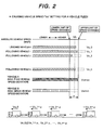
- Fig. 2 is a diagram explaining the principles of operation.
- Fig. 2 shows a status in which any vehicle speed "Vs" is set for one entire fleet of vehicles which are to be driven in line (fleet driving).
- Vs vehicle speed
- ACC mode since the set vehicle speed is controlled as an upper-limit vehicle speed during headway distance control, if the value of "Vs" when viewed in terms of absolute speed does not change between vehicles, fleet driving will be possible, but realistically, this is not probable.
- Figs. 3 to 9 are flowcharts showing examples of control.
- Fig. 3 is a flowchart showing an example in which the upper-limit vehicle speed during headway distance control is greater than the set value by a fixed speed, and this flowchart also corresponds to Fig. 2 explaining the principles of operation.
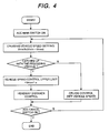
- Fig. 4 is a flowchart showing an example in which the upper-limit vehicle speed during headway distance control is set to a fixed value which is greater than the upper limit of the vehicle speed setting range by a fixed speed.
- map information supplied by a car navigation system or the information supplied by an automatic expressway charge collection system, or other information may be usable as an expressway identification means.
- Fig. 5 shows an example in which, when the vehicle speed is set to the upper limit, the upper-limit vehicle speed during headway distance control matches a value greater than the upper limit of the vehicle speed setting range by a fixed speed.
- Fig. 6 shows an example in which the upper-limit vehicle speed during headway distance control is greater than the speed of the preceding vehicle by a fixed speed.
- the response of the following vehicle also improves.
- a limiter is provided for the maximum vehicle control speed in this example.
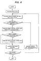
- Fig. 7 shows an example in which the upper-limit vehicle speed under headway distance control is increased by multiplying the set vehicle speed by a constant.
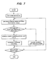
- Fig. 8 shows the example where the automatic vehicle speed control apparatus is provided with the follow-up drive prioritizing switch 15 by which, although conventional ACC mode is valid during the OFF status of the switch, an ACC mode that assigns priority to follow-up driving will be selected when the switch is set to the ON position.
- the switch does not always need to be provided downstream with respect to the ACC main switch, and can be, for example, a three-position switch provided on the same level as that of the ACC main switch, or may have an added function so that when the switch is set to ON, the upper limit of the vehicle speed will also be set automatically.
- the particular setting position of the follow-up drive prioritizing switch on the display device 10 can be displayed in a character/graphic format or may be displayed in a different display color.
- Fig. 9 shows an example in which, when the preceding vehicle is a heavy-duty truck, fleet driving at the same set vehicle speed as the speed of the preceding vehicle is enabled by increasing the upper limit of the vehicle speeds existing during headway distance control, to a value greater than the previously set speed.
- Fleet driving in compliance with the maximum speed limit of 90 km/h applied to heavy-duty trucks can be reliably achieved by limiting the type of preceding vehicle to a heavy-duty truck.
- a method that employs a vehicle-mounted camera, inter-vehicle communications, or the like, may be usable as a means of identifying heavy-duty trucks.
- the permissible errors of speedometer indications that are provided for inArticle 46 of the Safety Standards are "within the range from +15 to -10 percent at speeds of 35 kilometers or more per hour on flat paved roads", and since this range is specified as the integrated permissible error range that covers all conditions such as the error of the instrument itself, the deflection of tires due to loading, wear on the tires, or the air pressures thereof, provided that irrespective of the vehicle type, the maximum ACC-settable vehicle speed is "V km/h", the symbols " ⁇ " and “ ⁇ ” shown in the flowchart take values of "0.25 x V km/h or more" and "22/17 or more", respectively.
Abstract
Description
- The present invention relates to an automatic vehicle speed control apparatus to conduct constant speed driving control when the headway distance to the preceding vehicle is equal to, or greater than a set value, and to conduct headway distance control when the headway distance is smaller than the set value, and more particularly to follow-up driving under the headway distance control.
- The vehicles with (ACC) as an option are coming to be marketed in order to achieve driving comfort. The adaptive cruise control recognizes the behavior of the preceding vehicle by means of a laser radar or a millimeter radar and hereby implement automatic follow-up driving. when the headway distance is equal to, or greater than a set value, the own vehicle can run at a constant speed. When once the own vehicle has overtaken the preceding vehicle, the own vehicle can automatically run to maintain the set headway distance,
- Additionally, Vehicle control with steering wheel control, inter-vehicle communications, road-to-vehicle communications, and other factors added to ACC in order to achieve fleet driving (driving in line) on expressways or automobile-dedicated roads and hereby to improve traffic efficiency and reduce drivers' burdens, is also proposed.
- The above control system is disclosed in, for example, Japanese laid-open patent publications Nos. Hei 07-200991 and Hei 08-192662.
- Under these circumstances, the heavy-duty trucks that will be newly registered from September 2003 are obliged to be equipped with a 90-km/h speed limiting device in order to reduce accidents on expressways. This will increase the demand for the execution of fleet driving on expressways.
- To consider up to the collaborative control that uses inter-vehicle communications and/or road-to-vehicle communications, however, the unification of standards is first required. Therefore, it is difficult, for the moment, to apply such fleet driving to general vehicles.
- The Japanese laid-open patent publication No. Hei 07-200991 relates to a case in which the collaborative control using inter-vehicle communications is to be realized. Although fleet driving With ACC is possible, even if the same vehicle speed is set for a fleet, follow-up driving is not always possible because of idiosyncrasies in speed recognition between vehicles. Particularly, fleet driving at the ACC-settable maximum speed is difficult.
- Although the conventional ACC described in Japanese laid-open patent publication No. Hei 08-192662 is improved so as to enable follow-up with the preceding vehicle when its actual speed is increased above the set speed, fleet driving is not considered and therefore the set vehicle speed is limited to the value existing during the start of vehicle speed control. Accordingly, it is not always possible for following vehicles to follow the preceding vehicle when the same vehicle speed is set.
- An object of the present invention is to provide an automatic vehicle speed control apparatus by which, when the preceding vehicle is running within legal speed limits, all vehicles following the preceding vehicle can continue to run in line (fleet driving) and highly efficient and smooth flow of traffic and reduction in drivers' burdens can be achieved.
- The above object can be fulfilled by increasing the upper-limit value of the vehicle speed placed under the control of the headway distance, to a value moderately greater than the vehicle speed which is set beforehand.
-
- Fig. 1 is a system block diagram showing an embodiment of the present invention.
- Fig. 2 is a diagram explaining the principles of operation.
- Fig. 3 is a control flowchart showing an embodiment of the present invention.
- Fig. 4 is a control flowchart showing another embodiment of the present invention.
- Fig. 5 is a control flowchart showing a yet another embodiment of the present invention.
- Fig. 6 is a control flowchart showing a further embodiment of the present invention.
- Fig. 7 is a control flowchart showing a further embodiment of the present invention.
- Fig. 8 is a control flowchart showing a further embodiment of the present invention.
- Fig. 9 is a control flowchart showing a further embodiment of the present invention.
-
- The preferred embodiments of the present invention are described below using drawings. An example of a system block diagram of the automatic vehicle speed control apparatus pertaining to the invention is shown in Fig. 1. This automatic vehicle speed control apparatus is constructed so that the behavior of the preceding vehicle is recognized by a
radar device 1, and then the recognized behavior is checked against the information sent from avehicle speed sensor 2. The own vehicle runs at a constant speed when the headway distance is equal to, or greater than, the set value, and automatically follows the preceding vehicle at the set headway distance once the former has overtaken the latter. -
Vehicle controller 3 is the main controller for providing automatic speed control. The other inputs required for control include amain switch 4a for making the automatic speed control function valid and invalid, a setting switch 4b for setting the vehicle speed for constant-speed driving, a resuming switch 4c for resuming control after it has been canceled, a cancellation switch 4d for temporary cancellation, atap switch 4e for setting the headway time against the preceding vehicle, arelease switch 5 that operates only during the braking operations of the driver and does not operate during automatic braking, a brakeoil pressure sensor 6 that detects applied braking force, a steeringwheel angle sensor 7 that detects corner driving, a G-sensor 8, agear signal device 9 for detecting transmission gear status, and so on. - The set vehicle speed and control status are transmitted to the driver via a
display device 10. Thedisplay device 10 here can include a voice function in addition to screen display. When a voice function is included, eyes-free operations are realized, which is preferable in terms of safe driving. - Target commands from the
vehicle controller 3 activate anengine controller 11 to control the opening angle of a throttle (not shown in the figure), with the result that the amount of inlet air to anengine 12 and even the output thereof are adjusted. Also, abrake controller 13 controls abooster 14 or a hydraulic actuator (not shown in the figure), hereby adjusting a brakeoil pressure sensor 6. Finally, automatic speed control is provided by headway distance feedback control. - Follow-up
drive prioritizing switch 15 is a switch by which, although normal ACC mode is valid during the OFF status of the switch, an ACC mode that assigns priority to follow-up driving will be selected when the switch is set to the ON position. - Fig. 2 is a diagram explaining the principles of operation.
- More specifically, Fig. 2 shows a status in which any vehicle speed "Vs" is set for one entire fleet of vehicles which are to be driven in line (fleet driving). In normal ACC mode, since the set vehicle speed is controlled as an upper-limit vehicle speed during headway distance control, if the value of "Vs" when viewed in terms of absolute speed does not change between vehicles, fleet driving will be possible, but realistically, this is not probable.
- To follow the preceding vehicle, the own vehicle must be driven at a speed equal to, or higher than, that of the preceding vehicle. Even when the vehicle speed "Vs" is set for each vehicle, however, the actual speeds of individual vehicles when compared in absolute speed will differ ("Vs_0", "Vs_1", "Vs_2", ... "Vs_n") as shown in the figure. Fleet driving is established, only when the set speeds "Vs_1", "Vs_2", ... "Vs_n" of the following vehicles are all equal to, or greater than, the set speed "Vs_0" of the preceding vehicle.
- In this figure, since the set speed "Vs_1" of the following
vehicle 1 is greater than the set speed "Vs_0" of the leadingvehicle 0, follow-up in this zone is established, whereas, since the set speed "Vs_2" of the followingvehicle 2 is smaller than the set speed "Vs_1" of the followingvehicle 1, the followingvehicle 2 cannot follow thevehicle 2 in this zone and fleet driving is disturbed. - Let us here consider the upper and lower limits of speed changes when viewed in terms of absolute vehicle speed. If the difference between these upper and lower limits is taken as "α", it is possible, by changing the upper-limit vehicle speed of all following vehicles placed under headway distance control, from the set speed "Vs" to a value of "Vs+α" or more, to make the following vehicles run at a speed higher than that of the leading
vehicle 0, since the vehicle speed in the form of fleet driving matches the set speed ("Vsmax" or less) of the leadingvehicle 0, and thereby to make fleet driving possible since the differences in vehicle speed between vehicles can be absorbed. - Of course, it suffices just to set the upper-limit vehicle speed in headway distance control mode so that the differences in vehicle speed between vehicles are greater than the set speed, and the method of setting the upper-limit vehicle speed does not need to be limited to fixed-value addition described earlier in this Specification.
- Figs. 3 to 9 are flowcharts showing examples of control.
- Fig. 3 is a flowchart showing an example in which the upper-limit vehicle speed during headway distance control is greater than the set value by a fixed speed, and this flowchart also corresponds to Fig. 2 explaining the principles of operation.
- Fig. 4 is a flowchart showing an example in which the upper-limit vehicle speed during headway distance control is set to a fixed value which is greater than the upper limit of the vehicle speed setting range by a fixed speed. Although the response of the following vehicle is improved by using this method, the use thereof is limited to driving on expressways, since the vehicle automatically follows once the preceding vehicle has accelerated to the upper limit of the vehicle speed setting range.
- Although no such information is shown in the flowchart, the map information supplied by a car navigation system or the information supplied by an automatic expressway charge collection system, or other information may be usable as an expressway identification means.
- Fig. 5 shows an example in which, when the vehicle speed is set to the upper limit, the upper-limit vehicle speed during headway distance control matches a value greater than the upper limit of the vehicle speed setting range by a fixed speed. The adoption of this configuration makes it possible to reduce the uncomfortable feeling of the driver familiar with a conventional ACC system.
- Fig. 6 shows an example in which the upper-limit vehicle speed during headway distance control is greater than the speed of the preceding vehicle by a fixed speed. In this example, the response of the following vehicle also improves. However, since direct use of this method does not limit the fleet driving speed, a limiter is provided for the maximum vehicle control speed in this example.
- Fig. 7 shows an example in which the upper-limit vehicle speed under headway distance control is increased by multiplying the set vehicle speed by a constant.
- Fig. 8 shows the example where the automatic vehicle speed control apparatus is provided with the follow-up
drive prioritizing switch 15 by which, although conventional ACC mode is valid during the OFF status of the switch, an ACC mode that assigns priority to follow-up driving will be selected when the switch is set to the ON position. In this example, the switch does not always need to be provided downstream with respect to the ACC main switch, and can be, for example, a three-position switch provided on the same level as that of the ACC main switch, or may have an added function so that when the switch is set to ON, the upper limit of the vehicle speed will also be set automatically. In addition, the particular setting position of the follow-up drive prioritizing switch on thedisplay device 10 can be displayed in a character/graphic format or may be displayed in a different display color. - Fig. 9 shows an example in which, when the preceding vehicle is a heavy-duty truck, fleet driving at the same set vehicle speed as the speed of the preceding vehicle is enabled by increasing the upper limit of the vehicle speeds existing during headway distance control, to a value greater than the previously set speed. Fleet driving in compliance with the maximum speed limit of 90 km/h applied to heavy-duty trucks can be reliably achieved by limiting the type of preceding vehicle to a heavy-duty truck.
- A method that employs a vehicle-mounted camera, inter-vehicle communications, or the like, may be usable as a means of identifying heavy-duty trucks.
- The value at which the legally specified "integrated permissible error" of the speedometer used in the vehicle can be absorbed is based on the following concept: the permissible errors of speedometer indications that are provided for inArticle 46 of the Safety Standards are "within the range from +15 to -10 percent at speeds of 35 kilometers or more per hour on flat paved roads", and since this range is specified as the integrated permissible error range that covers all conditions such as the error of the instrument itself, the deflection of tires due to loading, wear on the tires, or the air pressures thereof, provided that irrespective of the vehicle type, the maximum ACC-settable vehicle speed is "V km/h", the symbols "α" and "β" shown in the flowchart take values of "0.25 x V km/h or more" and "22/17 or more", respectively.
- Of course, if the relevant law is amended, a concept similar to the above will be applied and "α" and "β" will correspondingly take the appropriate values. Also, as the values of "α" and "β" are increased, following vehicles will be more likely to follow the preceding vehicle if the driver thereof drives at a speed exceeding the set speed. It is desirable, therefore, that the vehicle speed be set to a value in the neighborhood of its lower limit.
- In any case, provided that the leading vehicle runs in ACC mode at a cruising speed within the legal speed limits, the steady driving vehicle speed of the following vehicle does not exceed the upper limit of the legal speed limits, and hereby, fleet driving can be realized.
- Since any changes or differences in vehicle speed between vehicles can be absorbed by increasing above the set vehicle speed the upper-limit value of the vehicle speed under the headway distance control conducted when the preceding vehicle is acquired using the ACC function, fleet driving at the same setting of the vehicle speed is possible and this, in turn, reduces the burdens of the drivers when they drive on expressways, and ensures highly efficient, smooth traffic flow.
- Reference numerals attached to the drawings show the following parts. 1 ... Radar device, 2 ... Vehicle speed sensor, 3 ... Vehicle controller, 4a ... Main switch, 4b ... Setting switch, 10 ... Display device, 11 ...Engine controller, 13 ... Brake controller, 15 ... Follow-up drive prioritizing switch.
Claims (15)
- An automatic vehicle speed control apparatus comprising:wherein constant speed driving control capable of maintaining the previously set speed of the vehicle is selected when the headway distance to said preceding vehicle is equal to, or greater than a previously set distance, and headway distance control maintaining the headway distance to said preceding vehicle at the required value is selected when the headway distance is smaller than the set distance,a vehicle speed detection unit (2) for detecting the speed of a vehicle;a headway distance detection unit (1) for detecting the headway distance to the immediately preceding vehicle; and a vehicle control unit (3) for accelerating and decelerating said own vehicle;
wherein fleet driving (driving in line) in which the own vehicle runs at the same set speed as that of the preceding vehicle is enabled by increasing the vehicle speed upper limit existing under headway distance control above the previously set speed. - An automatic vehicle speed control apparatus as set forth in Claim 1, wherein the upper limit of the vehicle speed under the control of the headway distance is increased above the previously set speed when the previously set speed of the vehicle is equal to the upper limit of its settable speeds.
- An automatic vehicle speed control apparatus as set forth in Claim 1, further comprising a switch for selecting whether the upper limit of the vehicle speed under the control of the headway distance is to be increased above the previously set speed or to be matched thereto.
- An automatic vehicle speed control apparatus as set forth in Claim 2, wherein the upper limit of the vehicle speed under the control of the headway distance is always controlled to a fixed value which is greater than the upper limit of the vehicle speed setting range by a fixed speed.
- An automatic vehicle speed control apparatus as set forth in Claim 3, wherein the upper limit of the vehicle speed under the control of the headway distance is controlled to a value which is greater than the set speed by a fixed speed.
- An automatic vehicle speed control apparatus as set forth in Claim, wherein the upper limit of the vehicle speed under the control of the headway distance is controlled to a value which is greater than the set speed by a fixed speed.
- An automatic vehicle speed control apparatus as set forth in Claim 2, wherein the upper limit of the vehicle speed under the control of the headway distance is controlled to a value which is greater than the speed of the preceding vehicle by a fixed speed.
- An automatic vehicle speed control apparatus as set forth in Claim 2, wherein the upper limit of the vehicle speed under the control of the headway distance is increased by multiplying the previously set speed by a constant.
- An automatic vehicle speed control apparatus as set forth in Claim 2, wherein the upper limit of the vehicle speed under the control of the headway distance is increased by multiplying the speed of the preceding vehicle by a constant.
- An automatic vehicle speed control apparatus as set forth in Claim 2, wherein follow-up driving in which the own vehicle can run at the same set speed as that of the preceding vehicle is enabled by not providing an upper limit for the vehicle speed existing under the control of the headway distance.
- An automatic vehicle speed control apparatus as set forth in Claim 5, wherein the fixed speed to be added to increase the vehicle speed above its set value is controlled to a value at which the legally specified "integrated permissible error" of the speedometer used in the vehicle can be absorbed.
- An automatic vehicle speed control apparatus as set forth in Claim 6, wherein the fixed value which has been obtained by adding a fixed speed to increase the vehicle speed the upper limit of its setting range is controlled to a value at which the legally specified "integrated permissible error" of the speedometer used in the vehicle can be absorbed.
- An automatic vehicle speed control apparatus as set forth in Claim 7, wherein the value added to increase the vehicle speed its set value is controlled to a value at which the legally specified "integrated permissible error" of the speedometer used in the vehicle can be absorbed.
- An automatic vehicle speed control apparatus as set forth in Claim 9, wherein the constant by which the set speed is to be multiplied is controlled to a value at which the legally specified "integrated permissible error" of the speedometer used in the vehicle can be absorbed.
- An automatic vehicle speed control apparatus as set forth in Claim 2, wherein the preceding vehicle is a heavy-duty truck.
Applications Claiming Priority (2)
| Application Number | Priority Date | Filing Date | Title |
|---|---|---|---|
| JP2002123337A JP3832380B2 (en) | 2002-04-25 | 2002-04-25 | Automatic vehicle speed control device |
| JP2002123337 | 2002-04-25 |
Publications (3)
| Publication Number | Publication Date |
|---|---|
| EP1359047A2 true EP1359047A2 (en) | 2003-11-05 |
| EP1359047A3 EP1359047A3 (en) | 2006-08-09 |
| EP1359047B1 EP1359047B1 (en) | 2009-03-04 |
Family
ID=29208124
Family Applications (1)
| Application Number | Title | Priority Date | Filing Date |
|---|---|---|---|
| EP03008835A Expired - Fee Related EP1359047B1 (en) | 2002-04-25 | 2003-04-24 | Automatic vehicle speed control apparatus |
Country Status (4)
| Country | Link |
|---|---|
| US (1) | US6975931B2 (en) |
| EP (1) | EP1359047B1 (en) |
| JP (1) | JP3832380B2 (en) |
| DE (1) | DE60326407D1 (en) |
Cited By (3)
| Publication number | Priority date | Publication date | Assignee | Title |
|---|---|---|---|---|
| EP1832463A3 (en) * | 2006-03-10 | 2009-09-09 | Nissan Motor Co., Ltd. | Vehicle headway distance control |
| EP1933292A3 (en) * | 2006-12-13 | 2009-09-16 | Daubner & Stommel GbR Bau-Werk-Planung | Method and system for influencing the traffic flow within a section of road |
| EP2461304A1 (en) * | 2009-07-28 | 2012-06-06 | Toyota Jidosha Kabushiki Kaisha | Vehicle control device, vehicle control method, and vehicle control system |
Families Citing this family (11)
| Publication number | Priority date | Publication date | Assignee | Title |
|---|---|---|---|---|
| JP3861865B2 (en) * | 2003-09-03 | 2006-12-27 | 株式会社デンソー | Vehicle operation device |
| US8626418B2 (en) * | 2005-12-15 | 2014-01-07 | International Business Machines Corporation | Method and system for monitoring speed of a vehicle |
| US20100082179A1 (en) * | 2008-09-29 | 2010-04-01 | David Kronenberg | Methods for Linking Motor Vehicles to Reduce Aerodynamic Drag and Improve Fuel Economy |
| US7801512B1 (en) * | 2009-03-05 | 2010-09-21 | Makor Issues And Rights Ltd. | Traffic speed enforcement based on wireless phone network |
| EP2302416B1 (en) * | 2009-09-28 | 2013-06-19 | Sick Ag | Safety scanner |
| KR20120139151A (en) * | 2011-06-17 | 2012-12-27 | 현대모비스 주식회사 | Smart cruise control system and method for controlling distance between vehicles |
| JP6201473B2 (en) * | 2013-07-17 | 2017-09-27 | 日産自動車株式会社 | Vehicle travel control device |
| US9272621B2 (en) * | 2014-04-24 | 2016-03-01 | Cummins Inc. | Systems and methods for vehicle speed management |
| CN104477168A (en) * | 2014-11-28 | 2015-04-01 | 长城汽车股份有限公司 | Automotive adaptive cruise system and method |
| US10967877B2 (en) | 2016-04-15 | 2021-04-06 | Honda Motor Co., Ltd. | Vehicle control system, vehicle control method, and vehicle control program |
| JP6938713B2 (en) * | 2016-04-15 | 2021-09-22 | 本田技研工業株式会社 | Vehicle control systems, vehicle control methods, and vehicle control programs |
Citations (3)
| Publication number | Priority date | Publication date | Assignee | Title |
|---|---|---|---|---|
| US4622636A (en) * | 1983-05-23 | 1986-11-11 | Nissan Motor Company, Limited | System and method for automatically controlling vehicle speed |
| DE4123110A1 (en) * | 1990-07-25 | 1992-01-30 | Volkswagen Ag | Motor vehicle speed controller with demand speed input - accepts externally generated max. speed, max. speed corresp. to road grip and selects lowest max. speed |
| JPH08192662A (en) * | 1995-01-20 | 1996-07-30 | Mitsubishi Motors Corp | Running control device of vehicle |
Family Cites Families (6)
| Publication number | Priority date | Publication date | Assignee | Title |
|---|---|---|---|---|
| JPH07200991A (en) | 1993-11-30 | 1995-08-04 | Sconick Joseph | Cooperative operation system of two or more vehicles |
| US5839534A (en) * | 1995-03-01 | 1998-11-24 | Eaton Vorad Technologies, Llc | System and method for intelligent cruise control using standard engine control modes |
| GB2328542A (en) * | 1997-08-20 | 1999-02-24 | Jaguar Cars | Vehicle adaptive cruise control |
| JP3620359B2 (en) * | 1999-08-10 | 2005-02-16 | 日産自動車株式会社 | Vehicle travel control device |
| DE10015300B4 (en) * | 2000-03-28 | 2018-04-05 | Robert Bosch Gmbh | Method and device for controlling the driving speed of a vehicle |
| EP1247685A1 (en) * | 2001-04-06 | 2002-10-09 | Ford Global Technologies, Inc., A subsidiary of Ford Motor Company | Control device for motor vehicle speed governor |
-
2002
- 2002-04-25 JP JP2002123337A patent/JP3832380B2/en not_active Expired - Fee Related
-
2003
- 2003-04-24 EP EP03008835A patent/EP1359047B1/en not_active Expired - Fee Related
- 2003-04-24 DE DE60326407T patent/DE60326407D1/en not_active Expired - Lifetime
- 2003-04-24 US US10/421,859 patent/US6975931B2/en not_active Expired - Lifetime
Patent Citations (3)
| Publication number | Priority date | Publication date | Assignee | Title |
|---|---|---|---|---|
| US4622636A (en) * | 1983-05-23 | 1986-11-11 | Nissan Motor Company, Limited | System and method for automatically controlling vehicle speed |
| DE4123110A1 (en) * | 1990-07-25 | 1992-01-30 | Volkswagen Ag | Motor vehicle speed controller with demand speed input - accepts externally generated max. speed, max. speed corresp. to road grip and selects lowest max. speed |
| JPH08192662A (en) * | 1995-01-20 | 1996-07-30 | Mitsubishi Motors Corp | Running control device of vehicle |
Non-Patent Citations (1)
| Title |
|---|
| PATENT ABSTRACTS OF JAPAN vol. 1996, no. 11, 29 November 1996 (1996-11-29) -& JP 08 192662 A (MITSUBISHI), 30 July 1996 (1996-07-30) * |
Cited By (6)
| Publication number | Priority date | Publication date | Assignee | Title |
|---|---|---|---|---|
| EP1832463A3 (en) * | 2006-03-10 | 2009-09-09 | Nissan Motor Co., Ltd. | Vehicle headway distance control |
| US7788012B2 (en) | 2006-03-10 | 2010-08-31 | Nissan Motor Co., Ltd. | Vehicle headway distance control apparatus and method |
| EP1933292A3 (en) * | 2006-12-13 | 2009-09-16 | Daubner & Stommel GbR Bau-Werk-Planung | Method and system for influencing the traffic flow within a section of road |
| US7880644B2 (en) | 2006-12-13 | 2011-02-01 | Daubner & Stommel GbR Bau-Werk -Planung | Method and system for influencing the traffic flow within a route section |
| EP2461304A1 (en) * | 2009-07-28 | 2012-06-06 | Toyota Jidosha Kabushiki Kaisha | Vehicle control device, vehicle control method, and vehicle control system |
| EP2461304A4 (en) * | 2009-07-28 | 2013-02-27 | Vehicle control device, vehicle control method, and vehicle control system |
Also Published As
| Publication number | Publication date |
|---|---|
| EP1359047B1 (en) | 2009-03-04 |
| US20030204300A1 (en) | 2003-10-30 |
| DE60326407D1 (en) | 2009-04-16 |
| JP3832380B2 (en) | 2006-10-11 |
| US6975931B2 (en) | 2005-12-13 |
| EP1359047A3 (en) | 2006-08-09 |
| JP2003317199A (en) | 2003-11-07 |
Similar Documents
| Publication | Publication Date | Title |
|---|---|---|
| EP1078803B1 (en) | Vehicle and device and method for controlling running of the same | |
| US10354156B2 (en) | Limiting speed display device for vehicle | |
| EP1288055A2 (en) | Adaptive cruise control apparatus and system | |
| EP1359047B1 (en) | Automatic vehicle speed control apparatus | |
| US8041493B2 (en) | Cruise control device and method for controlling the running of a vehicle | |
| WO2016129231A1 (en) | Inter-vehicle management device and inter-vehicle management method | |
| EP1065087A2 (en) | Automobile running control system for optimum inter-vehicle spacing | |
| CN103129556A (en) | Driving assistance system | |
| GB2454516A (en) | Vehicle speed control | |
| CN111483316B (en) | Vehicle and speed limit control method and device thereof | |
| US11299153B2 (en) | Vehicle traveling control apparatus | |
| CN112334371A (en) | Longitudinal guidance driver assistance system in a motor vehicle | |
| CN112313131B (en) | Driver assistance system and method for autopilot with automatic longitudinal guidance | |
| JP7256475B2 (en) | Vehicle running control device | |
| CN113183956A (en) | Constant-speed cruise control method and device, readable storage medium and automobile | |
| US20070142992A1 (en) | Method for improving a cruise control system | |
| US20230068472A1 (en) | Driving assistance apparatus, vehicle, driving control method, and program | |
| US11769406B2 (en) | Automobile | |
| US20230063897A1 (en) | Vehicle | |
| US20230192097A1 (en) | Vehicle control apparatus, vehicle, acceleration-and-deceleration control method, and vehicle control program | |
| JP2023027997A (en) | Automobile | |
| JP2023028560A (en) | Automobile | |
| CN116133925A (en) | Method and system for predicting the functional quality of a driver assistance function | |
| JP2021109559A (en) | Vehicle travel control device | |
| JP2023064491A (en) | Driving support device |
Legal Events
| Date | Code | Title | Description |
|---|---|---|---|
| PUAI | Public reference made under article 153(3) epc to a published international application that has entered the european phase |
Free format text: ORIGINAL CODE: 0009012 |
|
| AK | Designated contracting states |
Kind code of ref document: A2 Designated state(s): AT BE BG CH CY CZ DE DK EE ES FI FR GB GR HU IE IT LI LU MC NL PT RO SE SI SK TR |
|
| AX | Request for extension of the european patent |
Extension state: AL LT LV MK |
|
| PUAL | Search report despatched |
Free format text: ORIGINAL CODE: 0009013 |
|
| AK | Designated contracting states |
Kind code of ref document: A3 Designated state(s): AT BE BG CH CY CZ DE DK EE ES FI FR GB GR HU IE IT LI LU MC NL PT RO SE SI SK TR |
|
| AX | Request for extension of the european patent |
Extension state: AL LT LV MK |
|
| 17P | Request for examination filed |
Effective date: 20070209 |
|
| AKX | Designation fees paid |
Designated state(s): DE FR GB IT |
|
| 17Q | First examination report despatched |
Effective date: 20070718 |
|
| GRAP | Despatch of communication of intention to grant a patent |
Free format text: ORIGINAL CODE: EPIDOSNIGR1 |
|
| GRAS | Grant fee paid |
Free format text: ORIGINAL CODE: EPIDOSNIGR3 |
|
| GRAA | (expected) grant |
Free format text: ORIGINAL CODE: 0009210 |
|
| RIN1 | Information on inventor provided before grant (corrected) |
Inventor name: ADACHI, HIDEFUMI,C |
|
| AK | Designated contracting states |
Kind code of ref document: B1 Designated state(s): DE FR GB IT |
|
| REG | Reference to a national code |
Ref country code: GB Ref legal event code: FG4D |
|
| RAP2 | Party data changed (patent owner data changed or rights of a patent transferred) |
Owner name: HITACHI, LTD. |
|
| REF | Corresponds to: |
Ref document number: 60326407 Country of ref document: DE Date of ref document: 20090416 Kind code of ref document: P |
|
| PLBE | No opposition filed within time limit |
Free format text: ORIGINAL CODE: 0009261 |
|
| STAA | Information on the status of an ep patent application or granted ep patent |
Free format text: STATUS: NO OPPOSITION FILED WITHIN TIME LIMIT |
|
| 26N | No opposition filed |
Effective date: 20091207 |
|
| GBPC | Gb: european patent ceased through non-payment of renewal fee |
Effective date: 20090604 |
|
| PG25 | Lapsed in a contracting state [announced via postgrant information from national office to epo] |
Ref country code: GB Free format text: LAPSE BECAUSE OF NON-PAYMENT OF DUE FEES Effective date: 20090604 |
|
| PG25 | Lapsed in a contracting state [announced via postgrant information from national office to epo] |
Ref country code: IT Free format text: LAPSE BECAUSE OF FAILURE TO SUBMIT A TRANSLATION OF THE DESCRIPTION OR TO PAY THE FEE WITHIN THE PRESCRIBED TIME-LIMIT Effective date: 20090304 |
|
| REG | Reference to a national code |
Ref country code: FR Ref legal event code: PLFP Year of fee payment: 14 |
|
| REG | Reference to a national code |
Ref country code: FR Ref legal event code: PLFP Year of fee payment: 15 |
|
| REG | Reference to a national code |
Ref country code: FR Ref legal event code: PLFP Year of fee payment: 16 |
|
| PGFP | Annual fee paid to national office [announced via postgrant information from national office to epo] |
Ref country code: FR Payment date: 20200312 Year of fee payment: 18 |
|
| PGFP | Annual fee paid to national office [announced via postgrant information from national office to epo] |
Ref country code: DE Payment date: 20200415 Year of fee payment: 18 |
|
| REG | Reference to a national code |
Ref country code: DE Ref legal event code: R119 Ref document number: 60326407 Country of ref document: DE |
|
| PG25 | Lapsed in a contracting state [announced via postgrant information from national office to epo] |
Ref country code: FR Free format text: LAPSE BECAUSE OF NON-PAYMENT OF DUE FEES Effective date: 20210430 Ref country code: DE Free format text: LAPSE BECAUSE OF NON-PAYMENT OF DUE FEES Effective date: 20211103 |