EP1359028B1 - Bandage flexible non pneumatique - Google Patents
Bandage flexible non pneumatique Download PDFInfo
- Publication number
- EP1359028B1 EP1359028B1 EP03009138.3A EP03009138A EP1359028B1 EP 1359028 B1 EP1359028 B1 EP 1359028B1 EP 03009138 A EP03009138 A EP 03009138A EP 1359028 B1 EP1359028 B1 EP 1359028B1
- Authority
- EP
- European Patent Office
- Prior art keywords
- tyre according
- elastic articulation
- width
- elastic
- support elements
- Prior art date
- Legal status (The legal status is an assumption and is not a legal conclusion. Google has not performed a legal analysis and makes no representation as to the accuracy of the status listed.)
- Expired - Lifetime
Links
- 230000002787 reinforcement Effects 0.000 claims description 15
- 239000002131 composite material Substances 0.000 claims description 8
- 229920001971 elastomer Polymers 0.000 claims description 6
- 239000013536 elastomeric material Substances 0.000 claims description 4
- 239000011159 matrix material Substances 0.000 claims description 3
- NINIDFKCEFEMDL-UHFFFAOYSA-N Sulfur Chemical compound [S] NINIDFKCEFEMDL-UHFFFAOYSA-N 0.000 claims description 2
- 239000000806 elastomer Substances 0.000 claims description 2
- 239000004814 polyurethane Substances 0.000 claims description 2
- 229920002635 polyurethane Polymers 0.000 claims description 2
- 229920005992 thermoplastic resin Polymers 0.000 claims description 2
- 229920001187 thermosetting polymer Polymers 0.000 claims description 2
- 239000005864 Sulphur Substances 0.000 claims 1
- 150000001875 compounds Chemical class 0.000 claims 1
- 230000003100 immobilizing effect Effects 0.000 claims 1
- 239000000835 fiber Substances 0.000 description 9
- 238000005452 bending Methods 0.000 description 5
- 238000006073 displacement reaction Methods 0.000 description 3
- 239000000463 material Substances 0.000 description 3
- 239000003365 glass fiber Substances 0.000 description 2
- 239000000203 mixture Substances 0.000 description 2
- 230000035515 penetration Effects 0.000 description 2
- 229920005989 resin Polymers 0.000 description 2
- 239000011347 resin Substances 0.000 description 2
- 229920000049 Carbon (fiber) Polymers 0.000 description 1
- 241000897276 Termes Species 0.000 description 1
- 230000004323 axial length Effects 0.000 description 1
- 239000004917 carbon fiber Substances 0.000 description 1
- 230000006835 compression Effects 0.000 description 1
- 238000007906 compression Methods 0.000 description 1
- 239000000470 constituent Substances 0.000 description 1
- 238000010276 construction Methods 0.000 description 1
- 230000001186 cumulative effect Effects 0.000 description 1
- 125000004122 cyclic group Chemical group 0.000 description 1
- 230000003111 delayed effect Effects 0.000 description 1
- 230000005489 elastic deformation Effects 0.000 description 1
- 230000000763 evoking effect Effects 0.000 description 1
- 230000002349 favourable effect Effects 0.000 description 1
- 238000004519 manufacturing process Methods 0.000 description 1
- 238000011084 recovery Methods 0.000 description 1
- 239000011208 reinforced composite material Substances 0.000 description 1
- 239000012783 reinforcing fiber Substances 0.000 description 1
- 238000007789 sealing Methods 0.000 description 1
- 238000004513 sizing Methods 0.000 description 1
- 229910052717 sulfur Inorganic materials 0.000 description 1
- 239000011593 sulfur Substances 0.000 description 1
- 239000000725 suspension Substances 0.000 description 1
- 239000004634 thermosetting polymer Substances 0.000 description 1
- 210000003462 vein Anatomy 0.000 description 1
- XLYOFNOQVPJJNP-UHFFFAOYSA-N water Substances O XLYOFNOQVPJJNP-UHFFFAOYSA-N 0.000 description 1
- 238000004804 winding Methods 0.000 description 1
Images
Classifications
-
- B—PERFORMING OPERATIONS; TRANSPORTING
- B60—VEHICLES IN GENERAL
- B60C—VEHICLE TYRES; TYRE INFLATION; TYRE CHANGING; CONNECTING VALVES TO INFLATABLE ELASTIC BODIES IN GENERAL; DEVICES OR ARRANGEMENTS RELATED TO TYRES
- B60C7/00—Non-inflatable or solid tyres
- B60C7/10—Non-inflatable or solid tyres characterised by means for increasing resiliency
- B60C7/14—Non-inflatable or solid tyres characterised by means for increasing resiliency using springs
- B60C7/16—Non-inflatable or solid tyres characterised by means for increasing resiliency using springs of helical or flat coil form
-
- B—PERFORMING OPERATIONS; TRANSPORTING
- B60—VEHICLES IN GENERAL
- B60C—VEHICLE TYRES; TYRE INFLATION; TYRE CHANGING; CONNECTING VALVES TO INFLATABLE ELASTIC BODIES IN GENERAL; DEVICES OR ARRANGEMENTS RELATED TO TYRES
- B60C7/00—Non-inflatable or solid tyres
- B60C7/10—Non-inflatable or solid tyres characterised by means for increasing resiliency
- B60C7/12—Non-inflatable or solid tyres characterised by means for increasing resiliency using enclosed chambers, e.g. gas-filled
-
- B—PERFORMING OPERATIONS; TRANSPORTING
- B60—VEHICLES IN GENERAL
- B60C—VEHICLE TYRES; TYRE INFLATION; TYRE CHANGING; CONNECTING VALVES TO INFLATABLE ELASTIC BODIES IN GENERAL; DEVICES OR ARRANGEMENTS RELATED TO TYRES
- B60C7/00—Non-inflatable or solid tyres
- B60C7/24—Non-inflatable or solid tyres characterised by means for securing tyres on rim or wheel body
-
- B—PERFORMING OPERATIONS; TRANSPORTING
- B60—VEHICLES IN GENERAL
- B60C—VEHICLE TYRES; TYRE INFLATION; TYRE CHANGING; CONNECTING VALVES TO INFLATABLE ELASTIC BODIES IN GENERAL; DEVICES OR ARRANGEMENTS RELATED TO TYRES
- B60C9/00—Reinforcements or ply arrangement of pneumatic tyres
- B60C9/18—Structure or arrangement of belts or breakers, crown-reinforcing or cushioning layers
Definitions
- the present invention relates to tires mounted on wheels and designed to be able to carry a substantial load without inflation pressure, called non-pneumatic tires.
- the patent application WO 00/37269 proposes such a non-pneumatic elastic bandage. It describes a bearing structure essentially comprising a plurality of support elements arranged substantially radially, in a cyclic symmetry all around the circumference of the bandage.
- a number of support elements present in the contact area are subjected to significant bending, which allows them to develop a recovery effort of part of the load.
- An interconnection structure makes the support elements work together, transferring the stresses to the adjacent support elements.
- this bandage to carry a certain load comes from the bending stress of the support elements present in the contact area of the non-pneumatic elastic bandage, and it also comes from the stress also in bending, the support elements outside. of the contact area of the non-pneumatic elastic bandage, via the interconnection structure.
- the interconnection structure while being able to transmit a part of the loading of the support elements on the neighboring support elements, it is known that it is sufficiently flexible to allow relative displacements of the support elements, both by compared to others, not only in the radial direction but also in the circumferential direction.
- the difference in displacement of the support members in the radial direction corresponds to a difference in flexural stress of these.
- the displacement difference in the circumferential direction corresponds to a circumferential stressing of the interconnection structure, evidenced by the de-axialization.
- the object of the present invention is to improve the proposed carrier structure so as to give it considerably improved endurance while maintaining its very good ability to support the load.
- the invention provides a flexible bandage according to claim 1 of the circumference.
- the interconnection structure is arranged radially between the support members and the tread.
- the support elements are continuous, an anchor to a rim to the other passing in front of the tread.
- the interconnection structure is continuous circumferentially, and advantageously reinforced for example by cables or son or ribbons as will appear in the following.
- the invention proposes to produce elastic hinges independent of each other, separated from each other circumferentially, each being secured to one side of a support member and the other of the interconnection structure, to transmit the efforts between support elements and interconnection structure.
- the advantageous operation of the bandage proposed by the invention makes it possible to ensure good overall operation of the supporting structure while judiciously decoupling its constituent elements, guaranteeing excellent endurance combined with excellent performance.
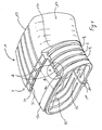
- the figure 1 illustrates an embodiment in which the bandage profile defines a toroidal internal cavity of oval section.
- the tire 1 comprises two axially separable fixing regions 11, two sidewalls 12 and a tread 13.
- the tread 13 has several parallel ribs, but this aspect is of course in no way limiting.
- the flanks 12 are rounded and occupy the greater part of the radial height of the tire 1.
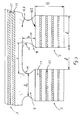
- the bearing structure comprises support elements 2.
- the support elements 2 are circumferentially adjacent and each extend substantially radially from a fastening zone 11 to the other.
- the support elements 2 comprise a stack of blades 21 of composite material, flexible, superimposed with the interposition of an elastomer layer 22 between the blades 21.
- the beam of blades thus bonded to one another forms a beam capable of be stressed in flexion.
- This aspect of the constitution of the laminate is however not limiting.
- the supporting structure also comprises an interconnection structure 3 between the support elements 2, preferably arranged radially between the tread and the support elements 2.
- the interconnection structure 3 is capable of distributing a circumferential radial stress between several support members while allowing movement differences between adjacent support members.
- the interconnection structure 3 preferably comprises a reinforcement oriented substantially circumferentially, for example a monofilament reinforcement 30 embedded in an elastomeric matrix 31, wound in several places to surround all the support elements 2 opposite the tread, itself preferably being rubber.
- the monofilament reinforcement turns 30 are in this particular case arranged radially over a layer 32 of an elastomeric material.
- the monofilament reinforcement 30 is wound substantially circumferentially, that is to say at an angle close to 0 ° with respect to a plane perpendicular to the axis. It may be a winding of said monofilament reinforcement 30 according to the desired number of turns or, which is equivalent, it may be monofilament rings in desired number. Note that one could, in variant of the monofilament reinforcement 30, use many cables among those commonly used as reinforcement to zero degree disposed within the tread of conventional tires. It would also be possible to use a reinforcement having the shape of a blade or a ribbon for example made of reinforced composite material, rather than a monofilament reinforcement. Again, the blade or ribbon is wound according to the desired number of turns or used in the form of rings used in a desired number.
- the composite material of the blades 21 and the monofilament reinforcement 30 comprises reinforcing fibers embedded in a resin.
- a thermosetting resin matrix is preferably used, but in some less demanding applications a thermoplastic resin may be suitable.
- the fibers are preferably arranged mainly longitudinally in each blade and in each monofilamentary reinforcement.
- glass fibers are used.
- many other fibers could be used, such as for example carbon fibers.
- a longilinear composite element of very great length with respect to the section, comprising substantially symmetrical technical fibers, said fibers being in long lengths, said fibers being impregnated in a thermoset resin having an initial expansion modulus of at least 2.3 GPa, in which said fibers are all substantially parallel to each other, the fiber content being between 30% and 80% of the overall weight of the elongate composite element, the density of the elongate composite element being less than 2.2, said elongated composite member having in flexion a compression breaking stress greater than the extension tensile stress, said elongate composite element having a compressive elastic deformation of at least 2%.
- said substantially symmetrical technical fibers are glass fibers.
- each support element 2 and the interconnection structure 3 are connected by elastic joints 4.
- Each support element 2 is radially surmounted by such an elastic articulation 4, which provides the mechanical connection between the support elements 2 and the interconnection structure 3, the forces transmitted from one to the other passing through said elastic joints 4.
- said support elements 2 are axially continuous with respect to the tread and beyond, to the attachment zones 11.
- each support element 2 comprises a median portion 25 substantially corresponding to the width of the interconnection structure 3. This is how it is done, in the non-limiting example illustrating the invention, said first portion (of each support member) disposed at least facing a portion of the tread.
- the interconnection structure 3 occupies substantially the entire width of the tread 13.
- each elastic articulation 4 makes it possible to connect the middle part 25 of the support elements 2 to the interconnection structure 3.
- each support element 2 comprises, on each side of the tire, a lateral portion 26 extending in the sidewall 12 and joining the attachment zone 11.
- said other portion (of each support member) disposed beyond the tread, where the support members are flexed when the tread is loaded.
- the elastic joint 4 proposed by the present invention could find application in many other embodiments of non-pneumatic tires whose bearing structure comprises support elements whose flexure under load provides the essential if not all the capacity supporting a load, and an interconnection structure between support members.
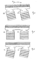
- each elastic hinge 4 has a flange 42 integral with a support member 2 and a head 43 secured to the interconnection structure 3. Between flange 42 and head 43, each elastic articulation 4 has free transverse faces 41, that is to say not in contact with another element of the bandage 1. The deformation of the transverse faces (see the explanations on the operation of the bandage below) n ' so is not upset by other elements whose presence would oppose it.
- Each elastic joint 4 is preferably of elastomeric material.
- a low hysteresis elastomeric material is used.
- sulfur vulcanizable rubber mixtures of the kind used for the sidewalls of tires gives good results.
- Such mixtures have a sufficiently low hysteresis and are sufficiently resistant to tearing, which enables the elastic joints to function properly in their role of transmitting the forces between the support elements 2 and the interconnection structure, while accepting deformations. important and repeated.
- Another material giving excellent results is polyurethane.
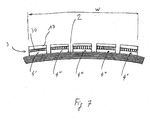
- each of the support members 2 has a width "L” in the circumferential direction and a height “H” in the radial direction. It can be seen that the circumferential gap between two adjacent arches has a length "l”. As for the elastic joints 4, they have a radial height "h” and a circumferential width "s”. It has already been seen that, in this embodiment of the invention, each elastic articulation 4 is continuous substantially over the entire width "w" of the tread 13 (see FIG. figure 1 ).
- each elastic articulation 4 has transverse faces 41 of substantially concave shape, so that the width of the elastic articulation 4 at the center of the radial thickness thereof, called width 1c , is somewhat less to the width L of the sole 42.
- width 1c the width of the elastic articulation 4 at the center of the radial thickness thereof.
- fixing zone is used here to designate in general the portion of the tire intended to cooperate with a rigid mechanical part that is also integral with a hub.
- the fixing zone is embedded on said mechanical part.
- the reader can usefully refer to the patent application WO 00/37269 supra.
- the attachment zone could equally well be single and one-piece, the radial section of the bandage then being closed, the choice of one or the other provision being any non-specific way of the present invention.
- the mounting axially separable fixing zones 11 it is seen in FIGS. 8 and 9 of the patent application WO 00/37269 , a kind of very narrow rim formed by two inner ferrules 380 and 381 and an insert 321, part of which forms an outer shell, which makes it possible to pinch each of the zones of fixing to obtain a recess of the radially inner portion of the carrier structure.
- the tire illustrating the invention comprises laminated elements arranged substantially radially.
- the laminated elements “de-radialize” somewhat during the passage in the contact area which, besides bending, also solicits them in torsion.
- the term “de-axialization” refers to the fact that reinforcements which are normally oriented radially in the sidewalls (carcass threads for a conventional radial tire, support elements for the embodiments of the tire described here) differ somewhat from this radial orientation. , the maximum of this difference being observed for the reinforcements opposite the entry and the exit of the contact area with the ground. Note that this deradialization is possible by the ability of the support elements to accommodate other deformations that a simple bending in a radial plane.
- the supporting structure by deforming, allows a certain flattening of the tread area concerned by the contact with the ground, so that the footprint of the loaded bandage has a certain surface, like well-known operation of inflated tires.
- the fixing area or zones are preferably located on a fraction corresponding to at most 50% of the distance axially separating the lateral limits of the bandage. Said radially inner portion of the flexible bearing structure is thus cantilevered enough pronounced beyond the fixing area or zones.
- a favorable constructive provision is that the support members are, just beyond the attachment zone, oriented in a direction substantially parallel to the axis of rotation. This is what appears in the example described.
- the bandage described being symmetrical, the fixing zone is substantially centered between the axial limits of said bandage, without this being limiting.
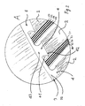
- the Figures 4 to 6 allow to visualize the portion of the elastic band corresponding to the contact air operating under a nominal load and show the deformation of the elastic joints 4 from the deformation of the support elements 2 and the interconnection structure 3.
- the deformation of the elastic joints at the entrance of the contact area ( figure 4 ), observing the elastic articulation 4A.
- the deformation of the elastic articulation 4C symmetrical to that of the elastic articulation 4A.
- the support elements 2 not only are bent, but also tilt relative to the average orientation of the interconnection structure 3.
- the presence of the elastic joints 4 makes a connection of the support elements 2 to the structure of the structure. interconnection 3 allowing the transfer of the mechanical stresses of service while allowing sufficient movement, including torsions of the support elements, to provide the entire carrier structure very high endurance.
- the support elements 2 are thus linked to the interconnection structure 3 with a kind of articulation, a little like the suspension arm elements are linked to the body of the vehicles most often by elastic rubber joints.
- the bandage has an outer skin 120 giving it a uniform appearance as seen in the right part of the figure 1 .
- This skin 120 covers all the support elements 2, from the outside thereof. There could also be a material between the support members 2, partially or completely filling the space between two adjacent support members 2.
- Another advantage of this skin is the sealing it provides to the internal cavity defined by the supporting structure, thus avoiding clogging of the internal cavity by the penetration of pebbles, water, mud; this is likely to disturb the operation of the bandage, even to damage it.
- Such a skin is however not designed to transmit forces or between support elements or between support elements and interconnection structure.
- the bandage does not comprise skin dressing the support elements 2 in the flanks, that is to say that the support elements 2 remain bare at least in the flanks, the flank of the final object having the appearance of the left part of the figure 1 .
- This part of the figure 1 can therefore be representative of the actual appearance of the flank, and not just be skinned.
- the tread could reveal communications with the internal cavity, that is to say not be waterproof.
- the interconnection structure could be installed radially inside the support elements at least partially, with the interposition of elastic hinges, and have a wear part (the tread ), circumferentially continuous or not, radially outside the support elements 2.
- the proposed tire architecture allows the construction of tires designed to operate without inflation pressure (non-pneumatic tire). Note that, and this is an important remark, nothing prevents to put in the proposed bandage a certain air pressure. It is sufficient, of course, to ensure that the bandage is airtight (presence of a skin 120 and non-perforated tread), or is provided with an inner tube. We can then adjust the characteristics, including flexibility, by playing on a certain pressurization "p" of the internal cavity. By making an analogy with an inflated tire, the pressurization "p" evoked here for the tire according to the invention compares with the pressure variation ⁇ p around a nominal pressure P for which said tire to be inflated is designed.
- the support elements 2 carry the load; they do not work completely isolated from each other, but they are interconnected by an interconnection structure 3 with interposition of elastic joints 4, so as to ensure good overall operation, avoiding shear too intense, and so as to provide good uniformity, that is to say a relative constancy of properties regardless of the circumferential position of the bandage relative to the ground.
Landscapes
- Engineering & Computer Science (AREA)
- Mechanical Engineering (AREA)
- Tires In General (AREA)
- Orthopedics, Nursing, And Contraception (AREA)
Applications Claiming Priority (2)
| Application Number | Priority Date | Filing Date | Title |
|---|---|---|---|
| FR0205474A FR2839015A1 (fr) | 2002-04-29 | 2002-04-29 | Bandage flexible non pneumatique |
| FR0205474 | 2002-04-29 |
Publications (2)
| Publication Number | Publication Date |
|---|---|
| EP1359028A1 EP1359028A1 (fr) | 2003-11-05 |
| EP1359028B1 true EP1359028B1 (fr) | 2015-01-28 |
Family
ID=28800105
Family Applications (1)
| Application Number | Title | Priority Date | Filing Date |
|---|---|---|---|
| EP03009138.3A Expired - Lifetime EP1359028B1 (fr) | 2002-04-29 | 2003-04-22 | Bandage flexible non pneumatique |
Country Status (8)
| Country | Link |
|---|---|
| US (1) | US6994135B2 (enExample) |
| EP (1) | EP1359028B1 (enExample) |
| JP (1) | JP2003320808A (enExample) |
| KR (1) | KR20030085494A (enExample) |
| CN (1) | CN1454796A (enExample) |
| BR (1) | BR0301038A (enExample) |
| FR (1) | FR2839015A1 (enExample) |
| RU (1) | RU2297334C2 (enExample) |
Families Citing this family (49)
| Publication number | Priority date | Publication date | Assignee | Title |
|---|---|---|---|---|
| ATE498020T1 (de) * | 2000-08-28 | 2011-02-15 | Oncomedx Inc | 5t4 rna in plasma und serum als marker für neoplastische erkrankungen |
| WO2005005168A1 (en) * | 2003-07-14 | 2005-01-20 | New Tech Tire Llc | Self-supporting tire of atmospheric internal pressure |
| US7546862B2 (en) * | 2005-05-06 | 2009-06-16 | New Tech Tire Llc | Non-pneumatic vehicle tire |
| ITTO20040120A1 (it) * | 2004-02-27 | 2004-05-27 | Fiat Auto Spa | Pneumatico per veicoli, in particolare, autoveicoli |
| FR2872820B1 (fr) * | 2004-07-07 | 2008-09-05 | Conception & Dev Michelin Sa | Systeme adhesif pour le collage direct d'un polyurethane cuit a du caoutchouc cru |
| ATE552957T1 (de) | 2006-01-27 | 2012-04-15 | Michelin Rech Tech | Verfahren zur herstellung eines verbundstoffrings |
| FR2910838B1 (fr) * | 2006-12-27 | 2009-03-06 | Conception & Dev Michelin Sa | Procede et dispositif de fabrication d'un anneau composite |
| US8109308B2 (en) * | 2007-03-27 | 2012-02-07 | Resilient Technologies LLC. | Tension-based non-pneumatic tire |
| US8104524B2 (en) * | 2007-03-27 | 2012-01-31 | Resilient Technologies Llc | Tension-based non-pneumatic tire |
| FR2921011B1 (fr) | 2007-09-14 | 2009-11-27 | Michelin Soc Tech | Produit stratifie composite. |
| FR2921013B1 (fr) | 2007-09-14 | 2009-11-27 | Soc Tech Michelin | Roue elastique non pneumatique. |
| US20090173421A1 (en) * | 2008-01-08 | 2009-07-09 | Freudenberg-Nok General Partnership | Flatless Hybrid Isolated Tire |
| FR2928865B1 (fr) | 2008-03-19 | 2010-03-19 | Michelin Soc Tech | Roue elastique non pneumatique |
| FR2928859B1 (fr) | 2008-03-19 | 2010-03-19 | Michelin Soc Tech | Produit stratifie composite |
| US20110180194A1 (en) * | 2008-09-29 | 2011-07-28 | Resilient Technologies, Llc | Run-flat device |
| US9108470B2 (en) * | 2008-09-29 | 2015-08-18 | Polaris Industries Inc. | Run-flat device |
| US8944125B2 (en) * | 2009-07-20 | 2015-02-03 | Polaris Industries Inc. | Tension-based non-pneumatic tire |
| US8176957B2 (en) * | 2009-07-20 | 2012-05-15 | Resilient Technologies, Llc. | Tension-based non-pneumatic tire |
| US9662939B2 (en) * | 2009-07-28 | 2017-05-30 | Bridgestone Americas Tire Operations, Llc | Tension-based non-pneumatic tire |
| FR2962938B1 (fr) | 2010-07-20 | 2013-06-14 | Michelin Soc Tech | Bandage flexible non pneumatique dont la structure porteuse comporte des lames metalliques |
| FR2964597B1 (fr) | 2010-09-09 | 2012-08-31 | Michelin Soc Tech | Roue elastique non pneumatique multietages |
| US8672006B2 (en) | 2011-07-15 | 2014-03-18 | New Tech Tire Llc | Non-pneumatic tire |
| WO2013129631A1 (ja) * | 2012-02-29 | 2013-09-06 | 株式会社ブリヂストン | タイヤ |
| US9573422B2 (en) | 2012-03-15 | 2017-02-21 | Polaris Industries Inc. | Non-pneumatic tire |
| CA2915483C (en) | 2013-06-15 | 2021-11-16 | Ronald Thompson | Annular ring and non-pneumatic tire |
| FR3009225B1 (fr) | 2013-08-01 | 2015-07-31 | Michelin & Cie | Monobrin en cvr (composite verre-resine) ameliore |
| EP3049257B1 (en) | 2013-09-24 | 2019-02-20 | Bridgestone Americas Tire Operations, LLC | Tire with toroidal element |
| FR3015363B1 (fr) | 2013-12-19 | 2016-02-05 | Michelin & Cie | Renfort multi-composite |
| EP3659820B1 (en) | 2013-12-24 | 2022-04-13 | Bridgestone Americas Tire Operations, LLC | Airless tire construction having variable stiffness |
| FR3020369B1 (fr) | 2014-04-29 | 2016-05-06 | Michelin & Cie | Renfort plat multi-composite |
| FR3031757B1 (fr) | 2015-01-21 | 2017-09-01 | Michelin & Cie | Renfort multi-composite verre-resine a proprietes ameliorees |
| WO2016126983A1 (en) | 2015-02-04 | 2016-08-11 | Advancing Mobility, Llc. | Non-pneumatic tire and other annular devices |
| WO2016189209A1 (fr) | 2015-05-28 | 2016-12-01 | Compagnie Generale Des Etablissements Michelin | Renfort multi-composite en verre-resine ameliore |
| FR3036651B1 (fr) | 2015-05-28 | 2017-05-19 | Michelin & Cie | Renfort plat multi-composite |
| US9834040B2 (en) | 2015-12-10 | 2017-12-05 | The Goodyear Tire & Rubber Company | Structurally supported tire |
| US9849721B2 (en) | 2015-12-10 | 2017-12-26 | The Goodyear Tire & Rubber Company | Structurally supported tire |
| CA3008846C (en) | 2015-12-16 | 2024-02-20 | Ronald H. Thompson | Track system for traction of a vehicle |
| US11318790B2 (en) * | 2016-04-13 | 2022-05-03 | The Goodyear Tire & Robber Company | Shear band and non-pneumatic tire |
| FR3056442A1 (fr) | 2016-09-27 | 2018-03-30 | Compagnie Generale Des Etablissements Michelin | Produit stratifie a base de caoutchouc silicone et de composite fibre-resine |
| FR3056444A1 (fr) | 2016-09-27 | 2018-03-30 | Compagnie Generale Des Etablissements Michelin | Roue elastique non pneumatique incorporant un stratifie a base de caoutchouc silicone et de composite fibre-resine |
| WO2019050549A1 (en) * | 2017-09-11 | 2019-03-14 | Compagnie Generale Des Etablissements Michelin | NON-PNEUMATIC TIRE |
| WO2019125468A1 (en) * | 2017-12-21 | 2019-06-27 | Compagnie Generale Des Etablissements Michelin | Reinforced resilient support for a non-pneumatic tire |
| FR3089995A3 (fr) | 2018-12-18 | 2020-06-19 | Michelin & Cie | Composition de résine comprenant un agent de réticulation spécifique |
| FR3089993A3 (fr) | 2018-12-18 | 2020-06-19 | Michelin & Cie | Composition de résine comprenant un agent de réticulation spécifique |
| US20220080774A1 (en) * | 2018-12-31 | 2022-03-17 | Compagnie Generale Des Etablissements Michelin | Improved spoke to compliant-band attachment |
| CN112959858A (zh) * | 2021-02-18 | 2021-06-15 | 南京航空航天大学 | 一种铰链组-柔性板协同式非充气车轮 |
| EP4331867B1 (fr) * | 2022-08-29 | 2025-03-12 | Venturi Lab SA | Roue déformable a support de charge non-pneumatique pour des conditions lunaires et martiennes |
| KR102677597B1 (ko) * | 2022-09-06 | 2024-06-21 | 주식회사 대동농기계 | 트레드부와 스포크부 접합공정효율이 향상된 비공기압 타이어와 이의 제조방법 |
| WO2025221279A1 (en) * | 2024-04-15 | 2025-10-23 | Triangle Tyre Co. Ltd. | Non-pneumatic tire |
Family Cites Families (19)
| Publication number | Priority date | Publication date | Assignee | Title |
|---|---|---|---|---|
| US1790992A (en) * | 1931-02-03 | Cushion tibe | ||
| FR374345A (fr) * | 1907-02-06 | 1907-06-10 | Gustave Emile Noe Isidore Erne | Bandage élastique pour roues de tous véhicules |
| FR495100A (fr) * | 1919-01-25 | 1919-09-27 | Jean Auguste Prince | Bandage de roues pour véhicules |
| US1346695A (en) * | 1919-06-03 | 1920-07-13 | Emory J Benedict | Resilient tire |
| US1450473A (en) * | 1921-05-12 | 1923-04-03 | Henry A Carson | Resilient tire |
| US1446939A (en) * | 1921-08-06 | 1923-02-27 | Sisti Salvatore Leo | Resilient wheel |
| US1610238A (en) * | 1924-10-13 | 1926-12-14 | Thomas J Benson | Cushion tire |
| US1625679A (en) * | 1926-01-27 | 1927-04-19 | George D Pearson | Automobile tire |
| US1647455A (en) * | 1926-10-26 | 1927-11-01 | Levinson Israel | Resilient tire |
| US1651211A (en) * | 1927-04-09 | 1927-11-29 | Lambert Leon | Automobile tire |
| US1822556A (en) * | 1927-08-09 | 1931-09-08 | Barber William | Cushion tire |
| US1687206A (en) * | 1927-09-17 | 1928-10-09 | Hatvani Gabriel | Spring tire |
| US2346799A (en) * | 1942-01-07 | 1944-04-18 | William A Tripp | Resilient tire |
| IT1118031B (it) * | 1977-06-24 | 1986-02-24 | Pirelli | Perfezionamento a pneumatici per ruote di veicoli |
| US4248287A (en) * | 1977-11-08 | 1981-02-03 | Brad Ragan, Inc. | Method of and apparatus for making flotation tire and tire product |
| US5236027A (en) * | 1992-02-24 | 1993-08-17 | Lu Tsai Chuan | Wheel assembly |
| FR2787388B1 (fr) * | 1998-12-18 | 2001-01-12 | Conception & Dev Michelin Sa | Bandage elastique utilisable de facon non pneumatique |
| HUP9902483A3 (en) * | 1999-01-05 | 2003-10-28 | New Tech Tire Llc New York | Tyre |
| EP1167080B1 (fr) | 2000-06-22 | 2007-01-03 | Conception et Développement Michelin S.A. | Bandage renforcé par un élément composite, ainsi qu'un tel élément |
-
2002
- 2002-04-29 FR FR0205474A patent/FR2839015A1/fr active Pending
-
2003
- 2003-04-22 EP EP03009138.3A patent/EP1359028B1/fr not_active Expired - Lifetime
- 2003-04-28 JP JP2003123847A patent/JP2003320808A/ja not_active Ceased
- 2003-04-28 KR KR10-2003-0026685A patent/KR20030085494A/ko not_active Ceased
- 2003-04-28 US US10/425,009 patent/US6994135B2/en not_active Expired - Lifetime
- 2003-04-28 RU RU2003112448/11A patent/RU2297334C2/ru not_active IP Right Cessation
- 2003-04-29 CN CN03124106A patent/CN1454796A/zh active Pending
- 2003-04-29 BR BR0301038-4A patent/BR0301038A/pt not_active Application Discontinuation
Also Published As
| Publication number | Publication date |
|---|---|
| BR0301038A (pt) | 2004-08-17 |
| US6994135B2 (en) | 2006-02-07 |
| RU2297334C2 (ru) | 2007-04-20 |
| CN1454796A (zh) | 2003-11-12 |
| US20030226630A1 (en) | 2003-12-11 |
| EP1359028A1 (fr) | 2003-11-05 |
| KR20030085494A (ko) | 2003-11-05 |
| JP2003320808A (ja) | 2003-11-11 |
| FR2839015A1 (fr) | 2003-10-31 |
Similar Documents
| Publication | Publication Date | Title |
|---|---|---|
| EP1359028B1 (fr) | Bandage flexible non pneumatique | |
| EP1056604B1 (fr) | Bandage flexible utilisable de facon non pneumatique | |
| EP2121355B1 (fr) | Structure de bourrelet de pneu | |
| WO2017005713A1 (fr) | Dispositif de type pneumatique pour vehicule | |
| WO2009044014A2 (fr) | Pneumatique utilisant une structure de renfort à fibres de section aplatie | |
| WO2016116491A1 (fr) | Dispositif de type pneumatique pour vehicule | |
| EP1640184A1 (fr) | Bandage flexible non pneumatique | |
| WO2016116490A1 (fr) | Dispositif de type pneumatique pour vehicule | |
| EP1237739B1 (fr) | Bourrelet pour pneumatique a mobilite etendue | |
| WO2019092343A1 (fr) | Pneumatique pour vehicule de tourisme | |
| EP3452308B1 (fr) | Adaptateur pour ensemble roulant et ensemble roulant le comprenant | |
| EP2429834B1 (fr) | Armature de renforcement bi matériaux de renforts et pneu comportant une telle armature | |
| WO2003010011A1 (fr) | Pneumatique ayant des flancs dissymetriques et renforces | |
| EP3490814A1 (fr) | Dispositif de type pneumatique pour véhicule | |
| CA2389891A1 (fr) | Appui de securite et ensemble appui et jante pour pneumatique comportant des moyens de centrage et a montage facilite | |
| WO2018206901A1 (fr) | Pneumatique avec un sommet comportant une couche de rigidification et une bande de roulement a forte adherence | |
| EP3490813A1 (fr) | Dispositif de type pneumatique pour vehicule | |
| EP1101633B1 (fr) | Pneumatique avec zone basse découplée | |
| WO2020245240A1 (fr) | Pneumatique comportant des flancs optimises et une armature de sommet constituee de deux couches de sommet de travail et d'une couche d'elements de renforcement circonferentiels | |
| WO2006024561A1 (fr) | Pneumatique a mobilite etendue avec zone d'ancrage a moment d'inertie eleve | |
| FR3067655A1 (fr) | Roue non-pneumatique comprenant une structure de renfort circonferentielle | |
| EP1515860B1 (fr) | Pneumatique avec nappe sommet imbriquee dans une nappe carcasse | |
| FR2910380A1 (fr) | Pneumatique a sommet rigide. | |
| EP3642052A1 (fr) | Dispositif de type pneumatique pour véhicule | |
| FR3066147A3 (fr) | Pneumatique avec un sommet comportant une couche de rigidification et une bande de roulement a forte adherence |
Legal Events
| Date | Code | Title | Description |
|---|---|---|---|
| PUAI | Public reference made under article 153(3) epc to a published international application that has entered the european phase |
Free format text: ORIGINAL CODE: 0009012 |
|
| AK | Designated contracting states |
Kind code of ref document: A1 Designated state(s): AT BE BG CH CY CZ DE DK EE ES FI FR GB GR HU IE IT LI LU MC NL PT RO SE SI SK TR |
|
| AX | Request for extension of the european patent |
Extension state: AL LT LV MK |
|
| 17P | Request for examination filed |
Effective date: 20040506 |
|
| AKX | Designation fees paid |
Designated state(s): AT BE BG CH CY CZ DE DK EE ES FI FR GB GR HU IE IT LI LU MC NL PT RO SE SI SK TR |
|
| 17Q | First examination report despatched |
Effective date: 20050302 |
|
| 17Q | First examination report despatched |
Effective date: 20050302 |
|
| RAP1 | Party data changed (applicant data changed or rights of an application transferred) |
Owner name: MICHELIN RECHERCHE ET TECHNIQUE S.A. |
|
| GRAP | Despatch of communication of intention to grant a patent |
Free format text: ORIGINAL CODE: EPIDOSNIGR1 |
|
| INTG | Intention to grant announced |
Effective date: 20140922 |
|
| GRAS | Grant fee paid |
Free format text: ORIGINAL CODE: EPIDOSNIGR3 |
|
| GRAA | (expected) grant |
Free format text: ORIGINAL CODE: 0009210 |
|
| AK | Designated contracting states |
Kind code of ref document: B1 Designated state(s): AT BE BG CH CY CZ DE DK EE ES FI FR GB GR HU IE IT LI LU MC NL PT RO SE SI SK TR |
|
| REG | Reference to a national code |
Ref country code: GB Ref legal event code: FG4D Free format text: NOT ENGLISH |
|
| REG | Reference to a national code |
Ref country code: CH Ref legal event code: EP |
|
| REG | Reference to a national code |
Ref country code: IE Ref legal event code: FG4D Free format text: LANGUAGE OF EP DOCUMENT: FRENCH |
|
| REG | Reference to a national code |
Ref country code: DE Ref legal event code: R096 Ref document number: 60347271 Country of ref document: DE Effective date: 20150312 |
|
| REG | Reference to a national code |
Ref country code: AT Ref legal event code: REF Ref document number: 708071 Country of ref document: AT Kind code of ref document: T Effective date: 20150315 |
|
| REG | Reference to a national code |
Ref country code: AT Ref legal event code: MK05 Ref document number: 708071 Country of ref document: AT Kind code of ref document: T Effective date: 20150128 |
|
| REG | Reference to a national code |
Ref country code: NL Ref legal event code: VDEP Effective date: 20150128 |
|
| PG25 | Lapsed in a contracting state [announced via postgrant information from national office to epo] |
Ref country code: BG Free format text: LAPSE BECAUSE OF FAILURE TO SUBMIT A TRANSLATION OF THE DESCRIPTION OR TO PAY THE FEE WITHIN THE PRESCRIBED TIME-LIMIT Effective date: 20150428 Ref country code: SE Free format text: LAPSE BECAUSE OF FAILURE TO SUBMIT A TRANSLATION OF THE DESCRIPTION OR TO PAY THE FEE WITHIN THE PRESCRIBED TIME-LIMIT Effective date: 20150128 Ref country code: ES Free format text: LAPSE BECAUSE OF FAILURE TO SUBMIT A TRANSLATION OF THE DESCRIPTION OR TO PAY THE FEE WITHIN THE PRESCRIBED TIME-LIMIT Effective date: 20150128 Ref country code: FI Free format text: LAPSE BECAUSE OF FAILURE TO SUBMIT A TRANSLATION OF THE DESCRIPTION OR TO PAY THE FEE WITHIN THE PRESCRIBED TIME-LIMIT Effective date: 20150128 |
|
| PG25 | Lapsed in a contracting state [announced via postgrant information from national office to epo] |
Ref country code: GR Free format text: LAPSE BECAUSE OF FAILURE TO SUBMIT A TRANSLATION OF THE DESCRIPTION OR TO PAY THE FEE WITHIN THE PRESCRIBED TIME-LIMIT Effective date: 20150429 Ref country code: NL Free format text: LAPSE BECAUSE OF FAILURE TO SUBMIT A TRANSLATION OF THE DESCRIPTION OR TO PAY THE FEE WITHIN THE PRESCRIBED TIME-LIMIT Effective date: 20150128 Ref country code: AT Free format text: LAPSE BECAUSE OF FAILURE TO SUBMIT A TRANSLATION OF THE DESCRIPTION OR TO PAY THE FEE WITHIN THE PRESCRIBED TIME-LIMIT Effective date: 20150128 |
|
| REG | Reference to a national code |
Ref country code: DE Ref legal event code: R097 Ref document number: 60347271 Country of ref document: DE |
|
| PG25 | Lapsed in a contracting state [announced via postgrant information from national office to epo] |
Ref country code: CZ Free format text: LAPSE BECAUSE OF FAILURE TO SUBMIT A TRANSLATION OF THE DESCRIPTION OR TO PAY THE FEE WITHIN THE PRESCRIBED TIME-LIMIT Effective date: 20150128 Ref country code: SK Free format text: LAPSE BECAUSE OF FAILURE TO SUBMIT A TRANSLATION OF THE DESCRIPTION OR TO PAY THE FEE WITHIN THE PRESCRIBED TIME-LIMIT Effective date: 20150128 Ref country code: RO Free format text: LAPSE BECAUSE OF FAILURE TO SUBMIT A TRANSLATION OF THE DESCRIPTION OR TO PAY THE FEE WITHIN THE PRESCRIBED TIME-LIMIT Effective date: 20150128 Ref country code: DK Free format text: LAPSE BECAUSE OF FAILURE TO SUBMIT A TRANSLATION OF THE DESCRIPTION OR TO PAY THE FEE WITHIN THE PRESCRIBED TIME-LIMIT Effective date: 20150128 Ref country code: EE Free format text: LAPSE BECAUSE OF FAILURE TO SUBMIT A TRANSLATION OF THE DESCRIPTION OR TO PAY THE FEE WITHIN THE PRESCRIBED TIME-LIMIT Effective date: 20150128 |
|
| PG25 | Lapsed in a contracting state [announced via postgrant information from national office to epo] |
Ref country code: MC Free format text: LAPSE BECAUSE OF FAILURE TO SUBMIT A TRANSLATION OF THE DESCRIPTION OR TO PAY THE FEE WITHIN THE PRESCRIBED TIME-LIMIT Effective date: 20150128 Ref country code: LU Free format text: LAPSE BECAUSE OF FAILURE TO SUBMIT A TRANSLATION OF THE DESCRIPTION OR TO PAY THE FEE WITHIN THE PRESCRIBED TIME-LIMIT Effective date: 20150422 |
|
| REG | Reference to a national code |
Ref country code: CH Ref legal event code: PL |
|
| PLBE | No opposition filed within time limit |
Free format text: ORIGINAL CODE: 0009261 |
|
| STAA | Information on the status of an ep patent application or granted ep patent |
Free format text: STATUS: NO OPPOSITION FILED WITHIN TIME LIMIT |
|
| GBPC | Gb: european patent ceased through non-payment of renewal fee |
Effective date: 20150428 |
|
| PG25 | Lapsed in a contracting state [announced via postgrant information from national office to epo] |
Ref country code: IT Free format text: LAPSE BECAUSE OF FAILURE TO SUBMIT A TRANSLATION OF THE DESCRIPTION OR TO PAY THE FEE WITHIN THE PRESCRIBED TIME-LIMIT Effective date: 20150128 |
|
| 26N | No opposition filed |
Effective date: 20151029 |
|
| REG | Reference to a national code |
Ref country code: IE Ref legal event code: MM4A |
|
| PG25 | Lapsed in a contracting state [announced via postgrant information from national office to epo] |
Ref country code: LI Free format text: LAPSE BECAUSE OF NON-PAYMENT OF DUE FEES Effective date: 20150430 Ref country code: CH Free format text: LAPSE BECAUSE OF NON-PAYMENT OF DUE FEES Effective date: 20150430 Ref country code: GB Free format text: LAPSE BECAUSE OF NON-PAYMENT OF DUE FEES Effective date: 20150428 |
|
| PG25 | Lapsed in a contracting state [announced via postgrant information from national office to epo] |
Ref country code: SI Free format text: LAPSE BECAUSE OF FAILURE TO SUBMIT A TRANSLATION OF THE DESCRIPTION OR TO PAY THE FEE WITHIN THE PRESCRIBED TIME-LIMIT Effective date: 20150128 |
|
| REG | Reference to a national code |
Ref country code: FR Ref legal event code: PLFP Year of fee payment: 14 |
|
| PG25 | Lapsed in a contracting state [announced via postgrant information from national office to epo] |
Ref country code: IE Free format text: LAPSE BECAUSE OF NON-PAYMENT OF DUE FEES Effective date: 20150422 |
|
| REG | Reference to a national code |
Ref country code: FR Ref legal event code: PLFP Year of fee payment: 15 |
|
| PG25 | Lapsed in a contracting state [announced via postgrant information from national office to epo] |
Ref country code: HU Free format text: LAPSE BECAUSE OF FAILURE TO SUBMIT A TRANSLATION OF THE DESCRIPTION OR TO PAY THE FEE WITHIN THE PRESCRIBED TIME-LIMIT; INVALID AB INITIO Effective date: 20030422 |
|
| PG25 | Lapsed in a contracting state [announced via postgrant information from national office to epo] |
Ref country code: CY Free format text: LAPSE BECAUSE OF FAILURE TO SUBMIT A TRANSLATION OF THE DESCRIPTION OR TO PAY THE FEE WITHIN THE PRESCRIBED TIME-LIMIT Effective date: 20150128 |
|
| PG25 | Lapsed in a contracting state [announced via postgrant information from national office to epo] |
Ref country code: PT Free format text: LAPSE BECAUSE OF FAILURE TO SUBMIT A TRANSLATION OF THE DESCRIPTION OR TO PAY THE FEE WITHIN THE PRESCRIBED TIME-LIMIT Effective date: 20150528 Ref country code: BE Free format text: LAPSE BECAUSE OF NON-PAYMENT OF DUE FEES Effective date: 20150430 |
|
| PG25 | Lapsed in a contracting state [announced via postgrant information from national office to epo] |
Ref country code: TR Free format text: LAPSE BECAUSE OF FAILURE TO SUBMIT A TRANSLATION OF THE DESCRIPTION OR TO PAY THE FEE WITHIN THE PRESCRIBED TIME-LIMIT Effective date: 20150128 |
|
| REG | Reference to a national code |
Ref country code: FR Ref legal event code: PLFP Year of fee payment: 16 |
|
| PGFP | Annual fee paid to national office [announced via postgrant information from national office to epo] |
Ref country code: DE Payment date: 20180420 Year of fee payment: 16 |
|
| PGFP | Annual fee paid to national office [announced via postgrant information from national office to epo] |
Ref country code: FR Payment date: 20180420 Year of fee payment: 16 |
|
| REG | Reference to a national code |
Ref country code: DE Ref legal event code: R119 Ref document number: 60347271 Country of ref document: DE |
|
| PG25 | Lapsed in a contracting state [announced via postgrant information from national office to epo] |
Ref country code: DE Free format text: LAPSE BECAUSE OF NON-PAYMENT OF DUE FEES Effective date: 20191101 |
|
| PG25 | Lapsed in a contracting state [announced via postgrant information from national office to epo] |
Ref country code: FR Free format text: LAPSE BECAUSE OF NON-PAYMENT OF DUE FEES Effective date: 20190430 |