EP1358970B1 - Hand tool with exchangable tool part magnetically secured to the handle - Google Patents
Hand tool with exchangable tool part magnetically secured to the handle Download PDFInfo
- Publication number
- EP1358970B1 EP1358970B1 EP02291126A EP02291126A EP1358970B1 EP 1358970 B1 EP1358970 B1 EP 1358970B1 EP 02291126 A EP02291126 A EP 02291126A EP 02291126 A EP02291126 A EP 02291126A EP 1358970 B1 EP1358970 B1 EP 1358970B1
- Authority
- EP
- European Patent Office
- Prior art keywords
- tool
- handle
- magnet
- ramp
- tool part
- Prior art date
- Legal status (The legal status is an assumption and is not a legal conclusion. Google has not performed a legal analysis and makes no representation as to the accuracy of the status listed.)
- Expired - Lifetime
Links
Images
Classifications
-
- A—HUMAN NECESSITIES
- A47—FURNITURE; DOMESTIC ARTICLES OR APPLIANCES; COFFEE MILLS; SPICE MILLS; SUCTION CLEANERS IN GENERAL
- A47G—HOUSEHOLD OR TABLE EQUIPMENT
- A47G21/00—Table-ware
- A47G21/02—Forks; Forks with ejectors; Combined forks and spoons; Salad servers
-
- B—PERFORMING OPERATIONS; TRANSPORTING
- B25—HAND TOOLS; PORTABLE POWER-DRIVEN TOOLS; MANIPULATORS
- B25G—HANDLES FOR HAND IMPLEMENTS
- B25G3/00—Attaching handles to the implements
- B25G3/02—Socket, tang, or like fixings
- B25G3/12—Locking and securing devices
-
- A—HUMAN NECESSITIES
- A47—FURNITURE; DOMESTIC ARTICLES OR APPLIANCES; COFFEE MILLS; SPICE MILLS; SUCTION CLEANERS IN GENERAL
- A47G—HOUSEHOLD OR TABLE EQUIPMENT
- A47G2200/00—Details not otherwise provided for in A47G
- A47G2200/10—Magnetism
- A47G2200/106—Permanent
-
- Y—GENERAL TAGGING OF NEW TECHNOLOGICAL DEVELOPMENTS; GENERAL TAGGING OF CROSS-SECTIONAL TECHNOLOGIES SPANNING OVER SEVERAL SECTIONS OF THE IPC; TECHNICAL SUBJECTS COVERED BY FORMER USPC CROSS-REFERENCE ART COLLECTIONS [XRACs] AND DIGESTS
- Y10—TECHNICAL SUBJECTS COVERED BY FORMER USPC
- Y10S—TECHNICAL SUBJECTS COVERED BY FORMER USPC CROSS-REFERENCE ART COLLECTIONS [XRACs] AND DIGESTS
- Y10S403/00—Joints and connections
- Y10S403/01—Magnetic
Definitions
- the invention relates to the field of hand tools, and more specifically to tableware and flatware.
- the invention concerns also tools and do-it-yourself.
- Tableware articles - forks, knives, spoon and the like - are integral devices. Some are moulded out of metal; other comprise a plastic handle moulded a metal tool.
- DE-A-24 26 810 disclosing the preambles of claims 1, 8 and 12 is considered at present as the closest prior art
- DE-A-24 26 810 and DE-A-24 26 884 disclose a set of tableware articles with are formed of separate handle and tool elements. They may be assembled using the force of a magnet.
- US-A-2 697 642 discloses a magnetic handle connection for brooms and other cleaning devices.
- a tapered magnet is provided on the broom or mop; the lower end of the handle is provided with a hole, into which a magnet is fitted.
- the invention provides a hand tool comprising a handle and a removable tool part, one of which is provided with a protruding section and a first magnet, the other of which is provided with a bore adapted to receive the protruding section and with a second magnet adapted to contact, or with very light airgap, the first magnet when the protruding section is received into the bore, wherein the tool part is provided with a first ramp, the handle tool part is provided with a second ramp matching the shape of the first ramp and the shape of the ramps is adapted to allow the magnets to contact, or with very light airgap, in one radial position of the tool part relative to the handle characterized in that the shape of the ramps is further adapted to cause an axial displacement of the handle relative to the tool part when the handle is rotated relative to the tool part .
- the magnetic force of the contacting magnets is higher than 10 N and is lower than 100 N.
- the protruding section and the bore have a circular cross section.
- the bore may be provided with an inner sheath.
- the second magnet is within the sheath.
- the invention provides a tableware handle, having at one end a bore, a magnet within the bore or without sheath typical and a ramp, the shape of the ramp being further adapted to cause the axial displacement of a matching ramp when rotated with respect to said matching ramp.
- the bore has a circular cross section.
- the bore may be provided with an inner sheath.
- the second magnet may be within the sheath.
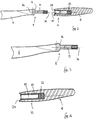
- the assembling end 8 of the handle is provided with a circular bore 18 for receiving the protruding section 12 of the tool part.
- this bore is further provided with an inner sheath 20 covering the inner wall of the opening.
- a second magnet 22 is provided in the end of the bore. The second magnet also lies within the sheath 20, which is preferred for the reasons discussed below.
- the handle is also provided with a second ramp 24. The shape of the second ramp matches the shape of the first ramp 16.
- the first and second ramps mate, so that the first magnet 14 contacts the second magnet 22.
- the tool is then assembled. In this assembled state, the tool appears integral to the user and may be used as any tool of the prior art.
- the first and second magnets lock the tool part and the handle in the axial direction, and prevent any axial movement. Any torque caused by using the tool 2 is transmitted from the tool part 6 to the handle 4 through the protruding part 12 and the bore 18 with its sheath 20. This assembly makes it possible to exert a high torque on the tool, without any risk that it disassembles.
- Figure 3 is an enlarged view of the assembling end 8 of the tool part.
- the features discussed above are not described again.
- Figure 3 shows that the first ramp 16 on the tool part is saddle-shaped. This provides a smooth and continuous transition from the tool part to the handle.
- the first ramp is not symmetric, so that there is only one radial position for assembling the tool on the handle.
- the maximum angle between the first ramp and a plane perpendicular to the axis 26 of the protruding part is between 5° and 45°; in the example, it is around 25°.
- the rate between the torque exerted on the tool part and the force axial force is proportional to the tangent of this angle.
- the angle may therefore be adapted to the strength of the magnets and to the radial torque deemed necessary for separating the tool.
- the proposed angle range ensures that the rate is between 30° and 45°. This is adapted to the magnet strength around 16 N discussed below.
- the protruding section may comprise an outer sheath. This may be helpful in providing a limited play between the protruding part and the bore in the handle. It may also be of help in case the material used for the tool part is not easily workable, e.g. for a moulded ceramic tool part.
- the first magnet is located in a bore 28 at the free end of the protruding section 12. It is maintained in this bore by any appropriate method, e.g. by gluing with an epoxy glue. The magnet could also be forced into the bore. The only limit to such a force assembly is the actual capability of the magnet to resist crushing. With a magnet compression strength in the usual range of 900 N/mm 2 or higher, this type of force assembly is possible. If a sheath were provided also over the protruding section, the magnet could be mounted within the sheath.
- the sheath is preferably made of amagnetic metal, for example stainless steel. This ensures magnetic hysteresis loop of the two magnets.
- the first and second magnet may be rare earth magnets, e.g. magnets of the type sold by Isolectra Martin, under reference NEODYNE 6 x 6 . They cause an axial strength of 16 N. This value was found to be sufficient for ensuring that the tool remains assembled in use. More generally, one could use a magnetic strength between 10 and 100 N. The lower value of this range ensures that the tool remains assembled. The higher value ensures that is remains possible to disassemble the tool, thanks to the ramps, without using additional specific tooling.
- rare earth magnets e.g. magnets of the type sold by Isolectra Martin, under reference NEODYNE 6 x 6 . They cause an axial strength of 16 N. This value was found to be sufficient for ensuring that the tool remains assembled in use. More generally, one could use a magnetic strength between 10 and 100 N. The lower value of this range ensures that the tool remains assembled. The higher value ensures that is remains possible to disassemble the tool, thanks to the ramps, without using additional specific tooling.
- the magnet 14 is not necessarily at the end of the protruding section 12. It could lie along the protruding section, thereby at the same time guiding the protruding part and ensuring the locking effect.
- an inner sheath is provided in bore 18 and no sheath is provided for protruding section 12.
- the protruding section is on the tool part, while the bore is provided in the handle. This is especially appropriate for tableware; one may also provide the bore in the tool part and the protruding section in the handle.
Abstract
Description
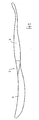
- figure 1 shows a schematic view of a hand tool according to the invention;
- figure 2 shows a partial cross section of the tool of figure 1, in a disassembled state;
- figure 3 shows an enlarged view of one end of the tool part of the hand tool of figure 1;
- figure 4 shows an enlarged view of the assembly end of the handle of the hand tool of figure 1.
- length of protruding section : about 24 mm;
- outer diameter of protruding section : 7 mm;
- diameter of first magnet : 6 mm;
- length of first magnet: 6 mm;
- thickness of sheath : 0,5 to 1 mm;
- floating between protruding section and sheath : 0,1 to 0,2 mm.
Claims (14)
- A hand tool (2) comprising a handle (4) and a removable tool part (6), one of which is provided with a protruding section (12) and a first magnet (14), the other of which is provided with a bore (18) adapted to receive the protruding section and with a second magnet (22) adapted to contact, or with very light airgap, the first magnet when the protruding section is received into the bore, wherein the tool part is provided with a first ramp (16), the handle tool part is provided with a second ramp (24) matching the shape of the first ramp (16) and the shape of the ramps (16,24) is adapted to allow the magnets (14,22) to contact, or with very light airgap, in one radial position of the tool part (6) relative to the handle (4) characterized in that the shape of the ramps (16,24) is further adapted to cause an axial displacement of the handle (4) relative to the tool part (6) when the handle (4) is rotated relative to the tool part (6).
- The tool of claim 1, wherein the magnetic force of the contacting magnets (14, 22) is higher than 10 N.
- The tool of claim 1 or 2, wherein the magnetic force of the contacting magnets (14, 22) is lower than 100 N.
- The tool of claim 1, 2 or 3, wherein the shape of the ramp (16, 24) is adapted to allow the magnets to contact in one radial position of the tool part (6) relative to the handle (4).
- The tool of one of claims 1 to 4, wherein the bore (18) is provided with an inner sheath (20).
- The tool of claim 5, wherein the second magnet (22) is within the sheath (20).
- The tool of one of claims 1 to 6, wherein the tool part is one of a spoon, fork and knife.
- A tableware handle, having at one end (8) a bore (18), a magnet (22) within the bore and a ramp (24), characterized in that the shape of the ramp (24) is further adapted to cause the axial displacement of a matching ramp when rotated with respect to said matching ramp.
- The handle of claim 8, wherein the bore (18) has a circular cross section.
- The handle of claim 8 or 9, wherein the bore (18) is provided with an inner sheath (20).
- The handle of claim 10, wherein the magnet (22) is within the sheath (20).
- A tableware tool part, having at the end opposite the tool part a protruding section (12), a magnet (14) and a ramp (16), characterized in that the shape of the ramp (16) is further adapted to cause the axial displacement of a matching ramp when rotated with respect to said matching ramp.
- The tool part of claim 12, wherein the magnet is located within a bore (28) at the end of the protruding section.
- The tool part of claim 12 or 13, wherein the bore (18) has a circular cross section.
Priority Applications (7)
| Application Number | Priority Date | Filing Date | Title |
|---|---|---|---|
| DE60207986T DE60207986T2 (en) | 2002-05-03 | 2002-05-03 | Hand tool with replaceable magnetically attached to the handle tool part |
| DK02291126T DK1358970T3 (en) | 2002-05-03 | 2002-05-03 | Hand tool with an interchangeable tool part magnetically attached to the handle |
| AT02291126T ATE312686T1 (en) | 2002-05-03 | 2002-05-03 | HAND TOOL WITH INTERCHANGEABLE MAGNETIC TOOL PART ATTACHED TO THE HANDLE |
| ES02291126T ES2254621T3 (en) | 2002-05-03 | 2002-05-03 | HAND TOOL WITH PART OF INTERCHANGEABLE TOOL MAGNETICALLY SET TO THE HANDLE. |
| PT02291126T PT1358970E (en) | 2002-05-03 | 2002-05-03 | MANUAL UTENSILS WITH MAGNETICALLY FIXED POSTAGE TO THE CABLE |
| EP02291126A EP1358970B1 (en) | 2002-05-03 | 2002-05-03 | Hand tool with exchangable tool part magnetically secured to the handle |
| US10/428,121 US7162802B2 (en) | 2002-05-03 | 2003-05-02 | Hand tool |
Applications Claiming Priority (1)
| Application Number | Priority Date | Filing Date | Title |
|---|---|---|---|
| EP02291126A EP1358970B1 (en) | 2002-05-03 | 2002-05-03 | Hand tool with exchangable tool part magnetically secured to the handle |
Publications (2)
| Publication Number | Publication Date |
|---|---|
| EP1358970A1 EP1358970A1 (en) | 2003-11-05 |
| EP1358970B1 true EP1358970B1 (en) | 2005-12-14 |
Family
ID=28799748
Family Applications (1)
| Application Number | Title | Priority Date | Filing Date |
|---|---|---|---|
| EP02291126A Expired - Lifetime EP1358970B1 (en) | 2002-05-03 | 2002-05-03 | Hand tool with exchangable tool part magnetically secured to the handle |
Country Status (7)
| Country | Link |
|---|---|
| US (1) | US7162802B2 (en) |
| EP (1) | EP1358970B1 (en) |
| AT (1) | ATE312686T1 (en) |
| DE (1) | DE60207986T2 (en) |
| DK (1) | DK1358970T3 (en) |
| ES (1) | ES2254621T3 (en) |
| PT (1) | PT1358970E (en) |
Families Citing this family (56)
| Publication number | Priority date | Publication date | Assignee | Title |
|---|---|---|---|---|
| US20050102845A1 (en) * | 2003-11-18 | 2005-05-19 | Alterra Holdings Corporation | Retention system for a hand tool combination |
| WO2006121798A1 (en) * | 2005-05-06 | 2006-11-16 | Jeffrey Frank | Tool assembly |
| US7909061B2 (en) | 2005-06-17 | 2011-03-22 | Masco Corporation Of Indiana | Magnetic coupling for sprayheads |
| US7753079B2 (en) | 2005-06-17 | 2010-07-13 | Masco Corporation Of Indiana | Magnetic coupling for sprayheads |
| US9315975B2 (en) | 2005-06-17 | 2016-04-19 | Delta Faucet Company | Magnetic coupling for sprayheads |
| US20100043815A1 (en) * | 2006-05-11 | 2010-02-25 | Frank Levy | Multihead Artist and Make-up Brush |
| US20070261188A1 (en) * | 2006-05-11 | 2007-11-15 | Frank Levy | Multi-head artist and make-up brush |
| US9339105B2 (en) | 2006-05-11 | 2016-05-17 | Switchpro, Llc | Multi-head artist and make-up brush |
| US7484427B2 (en) * | 2006-06-06 | 2009-02-03 | Bolt Bethel, Llc | Adjustable torque thread gauge assembly and method of calibration thereof |
| US20080016699A1 (en) * | 2006-07-19 | 2008-01-24 | Kuo Chi Chang | Structure for fastening sword blade to scabbard |
| US20080072719A1 (en) * | 2006-09-27 | 2008-03-27 | Burton Kozak | Non-ferrous bit for use with a magnetic chuck |
| US7530771B2 (en) * | 2006-09-27 | 2009-05-12 | Burton Kozak | Non-ferrous bit for use with a magnetic chuck |
| TWI454352B (en) * | 2006-11-17 | 2014-10-01 | 3M Innovative Properties Co | Ribbon curling device |
| US10155093B2 (en) | 2006-11-27 | 2018-12-18 | Frank Levy | Apparatus and method for producing CO2 enriched medical foam |
| US10322271B2 (en) | 2006-11-27 | 2019-06-18 | Frank Levy | Delivery system and method for the effective and reliable delivery of controlled amounts of a medical fluid |
| US10350399B2 (en) | 2006-11-27 | 2019-07-16 | Frank Levy | Apparatus and method for producing an enriched medical suspension of carbon dioxide |
| CN201067174Y (en) | 2007-05-14 | 2008-06-04 | 爱你士化妆用具(天津)有限公司 | Cosmetic brush with changeable brush head |
| US20090229130A1 (en) * | 2008-03-11 | 2009-09-17 | Swierski Scott T | Interchangeable toddler utensils utilizing novel retention mechanisms and a novel handle |
| CA2637501A1 (en) * | 2008-07-11 | 2010-01-11 | Trudy Braga | Candlewick holder remover |
| US20100089151A1 (en) * | 2008-10-09 | 2010-04-15 | Alberto Mantilla | Stackable measuring containers with removable handles |
| US20100263219A1 (en) * | 2008-12-17 | 2010-10-21 | Kempker Jeffrey A | Tool with ergonomic handle and replaceable cutter head |
| US20100242289A1 (en) * | 2009-03-30 | 2010-09-30 | Scott Roskam | Scissors utilizing a flexible and detachable thumb ring connection |
| US8627844B2 (en) * | 2009-10-30 | 2014-01-14 | Masco Corporation Of Indiana | Magnetic escutcheon mounting assembly |
| US8567430B2 (en) | 2009-10-30 | 2013-10-29 | Masco Corporation Of Indiana | Magnetic coupling for faucet handle |
| US20130133683A1 (en) * | 2009-11-13 | 2013-05-30 | Debra E. Guthans | Hair styling tool with removable handle |
| US8418700B2 (en) * | 2009-11-13 | 2013-04-16 | Debra E. Guthans | Hair styling assembly |
| US20110114111A1 (en) * | 2009-11-13 | 2011-05-19 | Guthans Debra E | Hair styling tool with detachable handle |
| US8726525B2 (en) * | 2010-01-13 | 2014-05-20 | Progressive International Corporation | Magnetic peeler set |
| US8505420B2 (en) * | 2010-06-21 | 2013-08-13 | Nelson B. Alfaro | Magnetized hand tools |
| ES2384925B1 (en) * | 2010-12-15 | 2013-05-20 | Electrodomésticos Taurus, S.L. | HANDBAND WITH SEPARABLE WORK HEAD. |
| CH705172B1 (en) | 2011-06-21 | 2016-08-15 | Benardeau Anne-Laure | Manual utensil, in particular component of a table cover. |
| US8789282B2 (en) | 2012-05-25 | 2014-07-29 | Shavelogic, Inc. | Magnetic attachment for shaving cartridge |
| US10272579B2 (en) | 2012-05-25 | 2019-04-30 | Shavelogic, Inc. | Magnetic attachment for shaving cartridge |
| US9284723B2 (en) | 2012-07-27 | 2016-03-15 | Kohler Co. | Magnetic docking faucet |
| US9181685B2 (en) | 2012-07-27 | 2015-11-10 | Kohler Co. | Magnetic docking faucet |
| US20140116211A1 (en) | 2012-10-25 | 2014-05-01 | Shavelogic, Inc. | Dedicated Attachment Systems for Consumer Products |
| US20140220200A1 (en) * | 2013-02-04 | 2014-08-07 | Andrew Di Guglielmo | Combined Utensil |
| US8985130B2 (en) * | 2013-03-12 | 2015-03-24 | Edgewater International, Inc. | Magnetically assisted coupling for segmented shaft |
| US20150250361A1 (en) * | 2014-03-04 | 2015-09-10 | Nedra Marion | Deformable Product Extraction Tool |
| US20160249757A1 (en) * | 2015-02-27 | 2016-09-01 | Harold Walter Hogarth | Finger-Mountable Eating Utensils and Related Methods |
| US9873604B2 (en) | 2015-03-06 | 2018-01-23 | Taphandles Llc | Adjustment mechanism for a beverage tap handle |
| US10026535B2 (en) * | 2015-12-31 | 2018-07-17 | Catch Latch, Llc | Mechanical magnetic connector structure |
| USD832648S1 (en) * | 2017-09-14 | 2018-11-06 | Mr. Bar-B-Q Products Llc | Utensil handle |
| CA3012798A1 (en) * | 2017-10-16 | 2019-04-16 | Thompson Brothers & Company, Llc | Connection mechanism for grilling utensil with a removable tip |
| USD894697S1 (en) | 2018-11-30 | 2020-09-01 | Rachael E. Stewart | Kitchen utensil |
| EP3771530A1 (en) * | 2019-07-31 | 2021-02-03 | Bic Violex S.A. | Mechanical assembly of a skin care device, skin care device and process for manufacturing thereof |
| USD943368S1 (en) * | 2019-11-13 | 2022-02-15 | Helen Of Troy Limited | Fruit cutting and scooping tool |
| USD942825S1 (en) * | 2020-01-30 | 2022-02-08 | Spectrum Diversified Designs, Llc | Kitchen tool |
| USD943366S1 (en) * | 2020-01-30 | 2022-02-15 | Spectrum Diversified Designs, Llc | Kitchen tool |
| US20220176576A1 (en) * | 2020-12-09 | 2022-06-09 | Jason D. Lopez Dba The Den Barbering | Razor tool and method |
| USD966795S1 (en) | 2021-02-22 | 2022-10-18 | Mr. Bar-B-Q Products Llc | Utensil handle |
| USD1005060S1 (en) | 2021-04-28 | 2023-11-21 | Rachael E. Stewart | Kitchen utensil |
| USD989575S1 (en) | 2021-08-23 | 2023-06-20 | Mr. Bar-B-Q Products Llc | Spatula |
| USD989576S1 (en) | 2021-08-27 | 2023-06-20 | Mr. Bar-B-Q Products Llc | Spatula |
| USD1012607S1 (en) | 2021-10-07 | 2024-01-30 | Mr. Bar-B-Q Products Llc | Utensil handle |
| USD1016554S1 (en) | 2021-10-08 | 2024-03-05 | Mr. Bar-B-Q Products Llc | Utensil handle |
Family Cites Families (20)
| Publication number | Priority date | Publication date | Assignee | Title |
|---|---|---|---|---|
| US2130661A (en) * | 1933-11-14 | 1938-09-20 | John Vanderkamp | Tooth brush |
| US2105119A (en) * | 1935-05-11 | 1938-01-11 | Washburn Co | Ferrule for handles and method of attaching same |
| US2697642A (en) * | 1949-09-28 | 1954-12-21 | Rudy Jerome | Magnetic handle connection |
| US2921326A (en) * | 1956-10-09 | 1960-01-19 | Iodent Chemical Company | Toothbrush |
| US3516697A (en) * | 1969-02-20 | 1970-06-23 | Raymar Inc | Connector for tubular members |
| GB1338074A (en) * | 1970-03-31 | 1973-11-21 | Spear Jackson Ashberry Ltd | Cutlery and flatware |
| DE2426810A1 (en) * | 1974-06-04 | 1976-03-11 | Geb Fanger Baerbel Bubik | Interchangeable handle cutlery set - has different handles for one head set for everyday and special occasion use |
| DE2426884A1 (en) * | 1974-06-04 | 1976-03-11 | Klaus Bonness | Interchangeable cutlery utensil head - has basic handle to receive compact heads by screw or spring fitting |
| US4821417A (en) * | 1987-04-09 | 1989-04-18 | Levine Anthony H | Device for facilitating use by handicapped of tools and utensils |
| US5327612A (en) * | 1993-03-02 | 1994-07-12 | Marshalltown Trowel Company | Plastic molded trowel handle having fingerguard and palm grip |
| US5355544A (en) * | 1993-11-22 | 1994-10-18 | The Procter & Gamble Company | Force-indicating toothbrush using magnetic latching |
| US5577426A (en) * | 1994-11-08 | 1996-11-26 | Snap-On Technologies, Inc. | Magnetic bit holder and hand tool incorporating same |
| US5950280A (en) * | 1997-08-11 | 1999-09-14 | Magic American Corporation | Utensil holding device |
| US5816337A (en) * | 1997-08-29 | 1998-10-06 | Kun-Chuan; Hsu | Handle of gardening tool |
| US6016728A (en) * | 1998-05-06 | 2000-01-25 | Bohl; Russell D. | Compact multi-purpose hand tool |
| US6048073A (en) * | 1999-04-23 | 2000-04-11 | Shiao; Hsuan-Sen | Telescopic hand tool |
| US20020092181A1 (en) * | 2001-01-16 | 2002-07-18 | Choi Yat Fay | 4-in-1 meal tools |
| US6513199B1 (en) * | 2001-10-26 | 2003-02-04 | Chun-Yong Cheng | Handle of a trowel |
| US6675483B2 (en) * | 2001-11-29 | 2004-01-13 | Helman Group, Ltd. | Combination barbecue tool |
| US6854919B2 (en) * | 2002-06-20 | 2005-02-15 | S.C. Johnson & Son, Inc. | Push-lock handle assembly |
-
2002
- 2002-05-03 AT AT02291126T patent/ATE312686T1/en not_active IP Right Cessation
- 2002-05-03 DK DK02291126T patent/DK1358970T3/en active
- 2002-05-03 PT PT02291126T patent/PT1358970E/en unknown
- 2002-05-03 ES ES02291126T patent/ES2254621T3/en not_active Expired - Lifetime
- 2002-05-03 EP EP02291126A patent/EP1358970B1/en not_active Expired - Lifetime
- 2002-05-03 DE DE60207986T patent/DE60207986T2/en not_active Expired - Lifetime
-
2003
- 2003-05-02 US US10/428,121 patent/US7162802B2/en not_active Expired - Lifetime
Also Published As
| Publication number | Publication date |
|---|---|
| DE60207986D1 (en) | 2006-01-19 |
| ES2254621T3 (en) | 2006-06-16 |
| PT1358970E (en) | 2006-05-31 |
| EP1358970A1 (en) | 2003-11-05 |
| DK1358970T3 (en) | 2006-05-08 |
| DE60207986T2 (en) | 2006-08-31 |
| US7162802B2 (en) | 2007-01-16 |
| US20030204914A1 (en) | 2003-11-06 |
| ATE312686T1 (en) | 2005-12-15 |
Similar Documents
| Publication | Publication Date | Title |
|---|---|---|
| EP1358970B1 (en) | Hand tool with exchangable tool part magnetically secured to the handle | |
| EP2296511B1 (en) | Combination chopstick utensil | |
| TWI342819B (en) | A magnetic device for holding and driving bits and fasteners | |
| US8240233B2 (en) | Connecting rod of a tool head | |
| US20050098002A1 (en) | Magnetic screw-holding device | |
| CA1247886A (en) | Handle with alternate tool orientation | |
| US4643052A (en) | Bevel gear driven offset screwdriver arrangement | |
| TW201006625A (en) | Tool chuck for screwdriver | |
| US20210354321A1 (en) | Coupling mechanism | |
| TWM581964U (en) | Easily-assembled torque wrench | |
| US4007929A (en) | Collapsible game racket | |
| US6392517B1 (en) | Magnetic retrieval tool with increased flux | |
| CA2131208C (en) | Handle for kitchen utensil | |
| JP2007509762A5 (en) | ||
| TW201100214A (en) | Tool positioning structure | |
| US8109207B2 (en) | Gripping member for a magnetised lid | |
| US5643095A (en) | Billiard cue having an axial aligning shaft-handle connector | |
| US20040037702A1 (en) | Ceiling fan blade for quick assembly | |
| US6058610A (en) | Decorative food cutter | |
| USD437739S1 (en) | Steak knife | |
| JP2001162545A (en) | Ratchet-type hand tool | |
| CN212146179U (en) | Screwdriver with magnet | |
| GB2328898A (en) | Cutlery | |
| CN212146178U (en) | Hand tool set with magnetic screwdriver | |
| TW201729927A (en) | Cutting tool key, cutting head key assembly and method of attaching cutting head to tool holder |
Legal Events
| Date | Code | Title | Description |
|---|---|---|---|
| PUAI | Public reference made under article 153(3) epc to a published international application that has entered the european phase |
Free format text: ORIGINAL CODE: 0009012 |
|
| AK | Designated contracting states |
Kind code of ref document: A1 Designated state(s): AT BE CH CY DE DK ES FI FR GB GR IE IT LI LU MC NL PT SE TR |
|
| AX | Request for extension of the european patent |
Extension state: AL LT LV MK RO SI |
|
| 17P | Request for examination filed |
Effective date: 20040426 |
|
| AKX | Designation fees paid |
Designated state(s): AT BE CH CY DE DK ES FI FR GB GR IE IT LI LU MC NL PT SE TR |
|
| 17Q | First examination report despatched |
Effective date: 20041220 |
|
| RIN1 | Information on inventor provided before grant (corrected) |
Inventor name: GRENIER, JEAN Inventor name: BENARDEAU, ANNE-LAURE |
|
| GRAP | Despatch of communication of intention to grant a patent |
Free format text: ORIGINAL CODE: EPIDOSNIGR1 |
|
| RIN1 | Information on inventor provided before grant (corrected) |
Inventor name: BENARDEAU, ANNE-LAURE Inventor name: GRENIER, JEAN |
|
| GRAS | Grant fee paid |
Free format text: ORIGINAL CODE: EPIDOSNIGR3 |
|
| GRAA | (expected) grant |
Free format text: ORIGINAL CODE: 0009210 |
|
| AK | Designated contracting states |
Kind code of ref document: B1 Designated state(s): AT BE CH CY DE DK ES FI FR GB GR IE IT LI LU MC NL PT SE TR |
|
| PG25 | Lapsed in a contracting state [announced via postgrant information from national office to epo] |
Ref country code: AT Free format text: LAPSE BECAUSE OF FAILURE TO SUBMIT A TRANSLATION OF THE DESCRIPTION OR TO PAY THE FEE WITHIN THE PRESCRIBED TIME-LIMIT Effective date: 20051214 |
|
| REG | Reference to a national code |
Ref country code: GB Ref legal event code: FG4D |
|
| REG | Reference to a national code |
Ref country code: CH Ref legal event code: EP |
|
| REG | Reference to a national code |
Ref country code: IE Ref legal event code: FG4D |
|
| REF | Corresponds to: |
Ref document number: 60207986 Country of ref document: DE Date of ref document: 20060119 Kind code of ref document: P |
|
| PG25 | Lapsed in a contracting state [announced via postgrant information from national office to epo] |
Ref country code: GR Free format text: LAPSE BECAUSE OF FAILURE TO SUBMIT A TRANSLATION OF THE DESCRIPTION OR TO PAY THE FEE WITHIN THE PRESCRIBED TIME-LIMIT Effective date: 20060314 |
|
| REG | Reference to a national code |
Ref country code: SE Ref legal event code: TRGR |
|
| PG25 | Lapsed in a contracting state [announced via postgrant information from national office to epo] |
Ref country code: IE Free format text: LAPSE BECAUSE OF NON-PAYMENT OF DUE FEES Effective date: 20060503 |
|
| REG | Reference to a national code |
Ref country code: DK Ref legal event code: T3 |
|
| REG | Reference to a national code |
Ref country code: SE Ref legal event code: TRGR |
|
| REG | Reference to a national code |
Ref country code: CH Ref legal event code: NV Representative=s name: CABINET ROLAND NITHARDT CONSEILS EN PROPRIETE INDU |
|
| PG25 | Lapsed in a contracting state [announced via postgrant information from national office to epo] |
Ref country code: MC Free format text: LAPSE BECAUSE OF NON-PAYMENT OF DUE FEES Effective date: 20060531 |
|
| REG | Reference to a national code |
Ref country code: PT Ref legal event code: SC4A Effective date: 20060313 |
|
| REG | Reference to a national code |
Ref country code: ES Ref legal event code: FG2A Ref document number: 2254621 Country of ref document: ES Kind code of ref document: T3 |
|
| ET | Fr: translation filed | ||
| PLBE | No opposition filed within time limit |
Free format text: ORIGINAL CODE: 0009261 |
|
| STAA | Information on the status of an ep patent application or granted ep patent |
Free format text: STATUS: NO OPPOSITION FILED WITHIN TIME LIMIT |
|
| 26N | No opposition filed |
Effective date: 20060915 |
|
| REG | Reference to a national code |
Ref country code: IE Ref legal event code: MM4A |
|
| PG25 | Lapsed in a contracting state [announced via postgrant information from national office to epo] |
Ref country code: CY Free format text: LAPSE BECAUSE OF FAILURE TO SUBMIT A TRANSLATION OF THE DESCRIPTION OR TO PAY THE FEE WITHIN THE PRESCRIBED TIME-LIMIT Effective date: 20051214 |
|
| REG | Reference to a national code |
Ref country code: FR Ref legal event code: PLFP Year of fee payment: 15 |
|
| REG | Reference to a national code |
Ref country code: FR Ref legal event code: PLFP Year of fee payment: 16 |
|
| REG | Reference to a national code |
Ref country code: CH Ref legal event code: NV Representative=s name: ACTOSPHERE SARL, CH |
|
| REG | Reference to a national code |
Ref country code: FR Ref legal event code: PLFP Year of fee payment: 17 |
|
| PGFP | Annual fee paid to national office [announced via postgrant information from national office to epo] |
Ref country code: LU Payment date: 20180522 Year of fee payment: 17 |
|
| PGFP | Annual fee paid to national office [announced via postgrant information from national office to epo] |
Ref country code: PT Payment date: 20180430 Year of fee payment: 17 Ref country code: ES Payment date: 20180607 Year of fee payment: 17 Ref country code: FI Payment date: 20180502 Year of fee payment: 17 Ref country code: DK Payment date: 20180517 Year of fee payment: 17 Ref country code: DE Payment date: 20180505 Year of fee payment: 17 |
|
| PGFP | Annual fee paid to national office [announced via postgrant information from national office to epo] |
Ref country code: TR Payment date: 20180502 Year of fee payment: 17 Ref country code: BE Payment date: 20180529 Year of fee payment: 17 Ref country code: NL Payment date: 20180526 Year of fee payment: 17 Ref country code: IT Payment date: 20180503 Year of fee payment: 17 |
|
| PGFP | Annual fee paid to national office [announced via postgrant information from national office to epo] |
Ref country code: SE Payment date: 20180525 Year of fee payment: 17 |
|
| PGFP | Annual fee paid to national office [announced via postgrant information from national office to epo] |
Ref country code: GB Payment date: 20180529 Year of fee payment: 17 |
|
| PGFP | Annual fee paid to national office [announced via postgrant information from national office to epo] |
Ref country code: CH Payment date: 20180829 Year of fee payment: 17 |
|
| REG | Reference to a national code |
Ref country code: DE Ref legal event code: R119 Ref document number: 60207986 Country of ref document: DE |
|
| REG | Reference to a national code |
Ref country code: CH Ref legal event code: PL |
|
| REG | Reference to a national code |
Ref country code: DK Ref legal event code: EBP Effective date: 20190531 |
|
| REG | Reference to a national code |
Ref country code: NL Ref legal event code: MM Effective date: 20190601 |
|
| GBPC | Gb: european patent ceased through non-payment of renewal fee |
Effective date: 20190503 |
|
| PG25 | Lapsed in a contracting state [announced via postgrant information from national office to epo] |
Ref country code: LI Free format text: LAPSE BECAUSE OF NON-PAYMENT OF DUE FEES Effective date: 20190531 Ref country code: CH Free format text: LAPSE BECAUSE OF NON-PAYMENT OF DUE FEES Effective date: 20190531 Ref country code: SE Free format text: LAPSE BECAUSE OF NON-PAYMENT OF DUE FEES Effective date: 20190504 Ref country code: PT Free format text: LAPSE BECAUSE OF NON-PAYMENT OF DUE FEES Effective date: 20191104 Ref country code: FI Free format text: LAPSE BECAUSE OF NON-PAYMENT OF DUE FEES Effective date: 20190503 |
|
| REG | Reference to a national code |
Ref country code: BE Ref legal event code: MM Effective date: 20190531 |
|
| PG25 | Lapsed in a contracting state [announced via postgrant information from national office to epo] |
Ref country code: LU Free format text: LAPSE BECAUSE OF NON-PAYMENT OF DUE FEES Effective date: 20190503 |
|
| PG25 | Lapsed in a contracting state [announced via postgrant information from national office to epo] |
Ref country code: GB Free format text: LAPSE BECAUSE OF NON-PAYMENT OF DUE FEES Effective date: 20190503 Ref country code: NL Free format text: LAPSE BECAUSE OF NON-PAYMENT OF DUE FEES Effective date: 20190601 Ref country code: DK Free format text: LAPSE BECAUSE OF NON-PAYMENT OF DUE FEES Effective date: 20190531 Ref country code: IT Free format text: LAPSE BECAUSE OF NON-PAYMENT OF DUE FEES Effective date: 20190503 Ref country code: DE Free format text: LAPSE BECAUSE OF NON-PAYMENT OF DUE FEES Effective date: 20191203 |
|
| REG | Reference to a national code |
Ref country code: SE Ref legal event code: EUG |
|
| PG25 | Lapsed in a contracting state [announced via postgrant information from national office to epo] |
Ref country code: BE Free format text: LAPSE BECAUSE OF NON-PAYMENT OF DUE FEES Effective date: 20190531 |
|
| REG | Reference to a national code |
Ref country code: ES Ref legal event code: FD2A Effective date: 20200925 |
|
| PG25 | Lapsed in a contracting state [announced via postgrant information from national office to epo] |
Ref country code: ES Free format text: LAPSE BECAUSE OF NON-PAYMENT OF DUE FEES Effective date: 20190504 |
|
| PGFP | Annual fee paid to national office [announced via postgrant information from national office to epo] |
Ref country code: FR Payment date: 20210415 Year of fee payment: 20 |
|
| PG25 | Lapsed in a contracting state [announced via postgrant information from national office to epo] |
Ref country code: TR Free format text: LAPSE BECAUSE OF NON-PAYMENT OF DUE FEES Effective date: 20190503 |