EP1358428B1 - Ausgleichsmechanismus - Google Patents
Ausgleichsmechanismus Download PDFInfo
- Publication number
- EP1358428B1 EP1358428B1 EP02711023A EP02711023A EP1358428B1 EP 1358428 B1 EP1358428 B1 EP 1358428B1 EP 02711023 A EP02711023 A EP 02711023A EP 02711023 A EP02711023 A EP 02711023A EP 1358428 B1 EP1358428 B1 EP 1358428B1
- Authority
- EP
- European Patent Office
- Prior art keywords
- cam
- counter
- balancing mechanism
- support
- axis
- Prior art date
- Legal status (The legal status is an assumption and is not a legal conclusion. Google has not performed a legal analysis and makes no representation as to the accuracy of the status listed.)
- Expired - Lifetime
Links
- 230000007246 mechanism Effects 0.000 title claims description 32
- 230000005484 gravity Effects 0.000 claims description 7
- 230000006835 compression Effects 0.000 claims description 3
- 238000007906 compression Methods 0.000 claims description 3
- 230000000694 effects Effects 0.000 description 3
- 239000012530 fluid Substances 0.000 description 2
- 238000004364 calculation method Methods 0.000 description 1
- 238000010276 construction Methods 0.000 description 1
- 230000001627 detrimental effect Effects 0.000 description 1
- 230000002452 interceptive effect Effects 0.000 description 1
- 238000012886 linear function Methods 0.000 description 1
- 238000000034 method Methods 0.000 description 1
- 230000002093 peripheral effect Effects 0.000 description 1
- 230000036316 preload Effects 0.000 description 1
- 239000007787 solid Substances 0.000 description 1
Images


Classifications
-
- F—MECHANICAL ENGINEERING; LIGHTING; HEATING; WEAPONS; BLASTING
- F16—ENGINEERING ELEMENTS AND UNITS; GENERAL MEASURES FOR PRODUCING AND MAINTAINING EFFECTIVE FUNCTIONING OF MACHINES OR INSTALLATIONS; THERMAL INSULATION IN GENERAL
- F16M—FRAMES, CASINGS OR BEDS OF ENGINES, MACHINES OR APPARATUS, NOT SPECIFIC TO ENGINES, MACHINES OR APPARATUS PROVIDED FOR ELSEWHERE; STANDS; SUPPORTS
- F16M11/00—Stands or trestles as supports for apparatus or articles placed thereon ; Stands for scientific apparatus such as gravitational force meters
- F16M11/02—Heads
- F16M11/04—Means for attachment of apparatus; Means allowing adjustment of the apparatus relatively to the stand
- F16M11/06—Means for attachment of apparatus; Means allowing adjustment of the apparatus relatively to the stand allowing pivoting
- F16M11/10—Means for attachment of apparatus; Means allowing adjustment of the apparatus relatively to the stand allowing pivoting around a horizontal axis
-
- F—MECHANICAL ENGINEERING; LIGHTING; HEATING; WEAPONS; BLASTING
- F16—ENGINEERING ELEMENTS AND UNITS; GENERAL MEASURES FOR PRODUCING AND MAINTAINING EFFECTIVE FUNCTIONING OF MACHINES OR INSTALLATIONS; THERMAL INSULATION IN GENERAL
- F16F—SPRINGS; SHOCK-ABSORBERS; MEANS FOR DAMPING VIBRATION
- F16F15/00—Suppression of vibrations in systems; Means or arrangements for avoiding or reducing out-of-balance forces, e.g. due to motion
- F16F15/28—Counterweights, i.e. additional weights counterbalancing inertia forces induced by the reciprocating movement of masses in the system, e.g. of pistons attached to an engine crankshaft; Attaching or mounting same
-
- F—MECHANICAL ENGINEERING; LIGHTING; HEATING; WEAPONS; BLASTING
- F16—ENGINEERING ELEMENTS AND UNITS; GENERAL MEASURES FOR PRODUCING AND MAINTAINING EFFECTIVE FUNCTIONING OF MACHINES OR INSTALLATIONS; THERMAL INSULATION IN GENERAL
- F16M—FRAMES, CASINGS OR BEDS OF ENGINES, MACHINES OR APPARATUS, NOT SPECIFIC TO ENGINES, MACHINES OR APPARATUS PROVIDED FOR ELSEWHERE; STANDS; SUPPORTS
- F16M2200/00—Details of stands or supports
- F16M2200/04—Balancing means
- F16M2200/041—Balancing means for balancing rotational movement of the head
Definitions
- EP-A-696702 discloses a mechanism according to the preamble to Claim 1.
- plate 3 rotates relative to a cylindrical body 6 and a hub 22 and again bearings are provided.
- Bodies 5 and 6 are connected to a common structure 7 which is mounted to, or indeed could form part of, a tripod or other stable structure upon which the head can be mounted. Where the head is a tilt and pan head, this structure 7 may be arranged to rotate about a vertical axis so that rotation in both the horizontal and vertical plane is achieved. This range or rotation is usually desirable.
- a return force F in a direction which is not normal to a cam surface also causes a force having a component at 90° to the force F and which serves to resist movement of the cam. It is this resisting force, which varies as the return force on the spring varies as the cam is moved longitudinally backwards and forwards, which serves to counter-balance the varying torque of the load tilting.
- the spring energy depends upon the preload and additional compression given by the cam height. It may be noted that cam height and gradient are interactive. Preferably, the profile is calculated for each point on the cam to within, say, one tenth of a degree but may be provided in other (eg larger) increments or by formula if produced on computer aided machinery and this can be done by those skilled in the art.
- Bodies 8 and 22 are required to be torsionally rigid with regard to each other, whilst allowing for relative axial movement. This can be achieved by many means such as keys, splines or similar. However, in order to avoid detrimental backlash or axial friction either chordal links or the method as follows may be used.
- a further pair of projections 20, 21 ( Figure 4) are provided on cam follower body 8 and, in use, these impinge upon a peripheral axial projection 22b from hub 22 which may require a cut-out 22a to clear axial movement of cam follower 10.
- the elements 20 and 21 may be of similar construction to the cam follower, having a projection from body 8 and a rotatable disk so that they, and therefore body 8, can slide longitudinally relative to hub 22. If, as may be preferred for a balance of forces, more than one projection is provided, then an equivalent number of associated pairs of elements 20 and 21 (cam followers) may be provided, being equispaced.
- Figure 4 shows parts of the apparatus which may be termed an 'energy pack' 40.
- This comprises drum 8, with followers 10,20,21, hub 22 and a lever 27 with shaft 23 that extends through plates 22,26 and into plate 2.
- the 'energy pack' can rotate about an axis which is offset from the axis of rotation O of the platform.
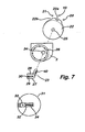
- Hub 22 (and therefore the cam followers and springs) rotates with shaft 23, as shaft 23 has a key 40 ( Figure 7), which fits into a keyway 25 in the central hole in hub 22.
- the cam is also mounted offset from the centre of plate 2 and.so the axis of rotation of the cam and resilient means is offset from the axis of rotation of the support (being coaxial with bearing 26).
Landscapes
- Engineering & Computer Science (AREA)
- General Engineering & Computer Science (AREA)
- Mechanical Engineering (AREA)
- Physics & Mathematics (AREA)
- Acoustics & Sound (AREA)
- Aviation & Aerospace Engineering (AREA)
- Accessories Of Cameras (AREA)
- Transmission Devices (AREA)
- Vehicle Step Arrangements And Article Storage (AREA)
- Manipulator (AREA)
Claims (17)
- Ausgleichsmechanismus, der einen Träger (1) zum Tragen eines um eine horizontale Achse zu neigenden Gegenstands; einen ringförmigen Nocken (4), der mit dem Träger bewegbar ist, dessen Nockenoberfläche in einer Richtung variiert, die in Bezug auf die Rotationsebene des Trägers normal ist; und einen Nockenläufer (9) aufweist, der durch ein federndes Mittel (12) belastet wird, wodurch, sowie der Träger rotiert, der Nockenläufer und das fedemde Mittel eine Rücksteltkraft verursachen, die ausgeübt werden soll, um im Wesentlichen das durch die Rotation des Trägers verursachte Drehmoment auszugleichen, wobei ein Mittel zum Variieren der Rückstettkraft in Übereinstimmung mit einer Last auf dem Träger bereitgestellt wird, dadurch gekennzeichnet, dass der Nocken um seine eigene Achse rotieren kann, die von der Rotationsachse des Trägers versetzt ist und Mittel zum Einstellen eines variablen Reaktionspunkts (E) einschließt, gegen die die Norkenläuferkraft, an oder versetzt von der Rotationsachse des Trägers, reagiert, um dadurch zu bewirken, dass die Rückstellkraft, die aufgrund der Rotation des Trägers um einen speziellen Winkel ausgeübt wird, variiert wird.
- Ausgleichmechanismus wie in Anspruch 1 beansprucht, der ein "Energiepaket" ('energy pack') umfasst, das angepasst ist, um eine Achse zu rotieren, die von der Rotationsachse des Trägers versetzt ist, wobei das Energiepaket eine Trommel (8) umfasst, die mindestens einen Nockenläufer (10), eine Nabe (22) und einen Hebel (27) aufweist, die angeordnet ist dem Energiepaket zu ermöglichen, um eine Achse zu rotieren, die von der Rotationsachse des Trägers versetzt ist.
- Ausgleichsmechanismus wie in Ansprüchen 1 oder 2 beansprucht, wobei der Nocken versetzt montiert ist, sodass die Rotationsachse des Nocken und des federnden Mittels von der Rotationsachse des Trägers versetzt ist.
- Ausgleichsmechanismus wie in einem beliebigen vorherigen Anspruch beansprucht, der Teil eines Schwenk-/Neigekopfes formt.
- Ausgleichsmechanismus wie in einem beliebigen vorherigen Anspruch beansprucht, wobei das federnde Mittel eine oder mehrere Federn (12) sind.
- Ausgleichsmechanismus wie in einem beliebigen vorherigen Anspruch beansprucht, wobei der Nocken einen allgemein ringförmigen, axialen Vorsprung aus einem Körper (5) formt und der Vorsprung eine variable Höhe aufweist, um die Nockenoberfläche bereitzustellen.
- Ausgleichsmechanismus wie in Anspruch 6 beansprucht, wobei der Träger auf zwei mit Abstand angeordneten Platten (2, 3) montiert ist, wovon eine den Nocken trägt.
- Ausgleichsmechanismus wie in Anspruch 7 beansprucht, wobei mindestens ein Nockenläufer an einem Körper (8) bereitgestellt ist, der federnd gegen eine Nabe montiert ist, die für relative rotierende Bewegung mit der anderen der besagten Platten angepasst ist.
- Ausgleichsmechanismus wie in Anspruch 8 beansprucht, wobei der Körper in den Bereich passt, der durch den ringförmigen Nocken definiert ist und der oder jeder Nockenläufer nach außen aus dem Körper hervorsteht.
- Ausgleichsmechanismus wie in einem beliebigen vorherigen Anspruch beansprucht, wobei das Nockenprofil ausgewählt ist, Folgendes zu berücksichtigen:(a) das durch eine außermittig kommende Last gegebene Moment;(b) Änderung in der effektiven Länge des Hebels, aufgrund einer um die Achse schwenkenden Last;(c) Federenergie, aufgrund von Kompression, die aus der Nockenhöhe herrührt; und(d) Gradient des Nocken.
- Ausgleichsmechanismus wie in einem beliebigen vorherigen Anspruch beansprucht, wobei der oder jeder Nockenläufer so profiliert ist, dass sich der Nocken relativ dazu bewegt
- Ausgleichsmechanismus wie in einem beliebigen vorherigen Anspruch beansprucht, der eine Vielheit in gleichen Abständen angeordneter Nachläufer umfasst.
- Ausgleichsmechanismus wie in einem beliebigen vorherigen Anspruch beansprucht, der Mittel zur Kompensation für eine Änderung der Last oder der Distanz des Schwerpunkts der Last von einem Drehzapfen einschließt.
- Ausgleichsmechanismus wie in Anspruch 13 beansprucht, der Mittel für die Auswahl eines Reaktionspunkts aufweist.
- Ausgleichsmechanismus wie in Anspruch 14 beansprucht, wobei ein Hebel (23), der Teil eines Energiepakets bildet, eine Keilnut (25) formt und ein Keil (40) wählbar in eine variable Position in der Keilnut befestigt wird, um einen variablen Drehzapfen-Reaktionspunkt zu bilden.
- Ausgleichsmochanismus wie in einem beliebigen der Ansprüche 1 bis 3 beansprucht, wobei der Nocken ringförmig ist und der oder jeder Nockenläufer auf einem Körper bereitgestellt ist, der sich innerhalb des ringförmigen Nockens befindet und nach außen aus dem Körper hervorsteht.
- Schwenk-/Neigekopf, der einen Ausgteichsmechanismus, wie in einem beliebigen vorherigen Anspruch beansprucht, umfasst.
Applications Claiming Priority (3)
| Application Number | Priority Date | Filing Date | Title |
|---|---|---|---|
| GBGB0103180.6A GB0103180D0 (en) | 2001-02-09 | 2001-02-09 | Counter-balancing mechanism |
| GB0103180 | 2001-02-09 | ||
| PCT/GB2002/000529 WO2002065013A1 (en) | 2001-02-09 | 2002-02-08 | Counter-balancing mechanism |
Publications (2)
| Publication Number | Publication Date |
|---|---|
| EP1358428A1 EP1358428A1 (de) | 2003-11-05 |
| EP1358428B1 true EP1358428B1 (de) | 2006-05-03 |
Family
ID=9908390
Family Applications (1)
| Application Number | Title | Priority Date | Filing Date |
|---|---|---|---|
| EP02711023A Expired - Lifetime EP1358428B1 (de) | 2001-02-09 | 2002-02-08 | Ausgleichsmechanismus |
Country Status (10)
| Country | Link |
|---|---|
| US (1) | US7055791B2 (de) |
| EP (1) | EP1358428B1 (de) |
| JP (1) | JP4173737B2 (de) |
| AU (1) | AU2002229918B2 (de) |
| CA (1) | CA2437590C (de) |
| DE (1) | DE60211116T2 (de) |
| ES (1) | ES2262786T3 (de) |
| GB (1) | GB0103180D0 (de) |
| WO (1) | WO2002065013A1 (de) |
| ZA (1) | ZA200306151B (de) |
Families Citing this family (10)
| Publication number | Priority date | Publication date | Assignee | Title |
|---|---|---|---|---|
| JP3880848B2 (ja) * | 2001-12-05 | 2007-02-14 | 松下電器産業株式会社 | 監視カメラ装置 |
| DE10211046B4 (de) * | 2002-03-13 | 2004-04-29 | Sachtler Gmbh & Co. Kg | Stativkopf, insbesondere Kamerastativkopf |
| US20040223062A1 (en) * | 2003-05-05 | 2004-11-11 | Richard Pettegrew | Pan and tilt camera system |
| US7746511B2 (en) | 2004-04-23 | 2010-06-29 | Symbol Technologies, Inc. | Scan head rotation at different optimum angles |
| JP4900734B2 (ja) * | 2009-03-19 | 2012-03-21 | 徳真電機工業株式会社 | ストッパ装置、及び連続運搬装置 |
| JP5513090B2 (ja) * | 2009-12-04 | 2014-06-04 | 学校法人慶應義塾 | ヒンジ型機械的荷重補償機構 |
| US9068602B2 (en) * | 2011-11-10 | 2015-06-30 | Low Boon Hoe | Locking mechanism for the support arm elbow of a selectively adjustable multipurpose support stand |
| ITUA20162628A1 (it) * | 2016-04-15 | 2017-10-15 | Vitec Imaging Solutions S P A | Testa di supporto bilanciata per apparecchiature video-fotografiche |
| DE102017215152A1 (de) * | 2017-08-30 | 2019-02-28 | Carl Zeiss Meditec Ag | Vorrichtung zur Erzeugung eines Drehmoments |
| JP6694625B1 (ja) * | 2019-12-05 | 2020-05-20 | 株式会社A−Traction | 受動関節装置 |
Family Cites Families (7)
| Publication number | Priority date | Publication date | Assignee | Title |
|---|---|---|---|---|
| GB1524461A (en) * | 1976-01-17 | 1978-09-13 | Vinten Ltd | Tilt mountling heads |
| US4083524A (en) * | 1976-09-10 | 1978-04-11 | Oconnor Chadwell | Panhead drag mechanism |
| JPS62274194A (ja) * | 1986-05-23 | 1987-11-28 | 株式会社 昭特製作所 | カメラ用雲台の平衡装置 |
| US4959671A (en) * | 1989-02-09 | 1990-09-25 | Heiwa Seiki Kogyo Co., Ltd. | Vertical tilting apparatus of tripod head |
| JPH0629594Y2 (ja) * | 1989-06-07 | 1994-08-10 | 株式会社ダイワ | カメラ用雲台のカウンターバランス機構 |
| JPH0544890A (ja) * | 1991-08-09 | 1993-02-23 | Heiwa Seiki Kogyo Kk | 雲 台 |
| US5553821A (en) * | 1994-08-09 | 1996-09-10 | Heiwa Seiki Kogyo Co., Ltd. | Counterbalancing unit |
-
2001
- 2001-02-09 GB GBGB0103180.6A patent/GB0103180D0/en not_active Ceased
-
2002
- 2002-02-08 EP EP02711023A patent/EP1358428B1/de not_active Expired - Lifetime
- 2002-02-08 AU AU2002229918A patent/AU2002229918B2/en not_active Ceased
- 2002-02-08 DE DE60211116T patent/DE60211116T2/de not_active Expired - Lifetime
- 2002-02-08 US US10/467,686 patent/US7055791B2/en not_active Expired - Lifetime
- 2002-02-08 ES ES02711023T patent/ES2262786T3/es not_active Expired - Lifetime
- 2002-02-08 CA CA2437590A patent/CA2437590C/en not_active Expired - Fee Related
- 2002-02-08 JP JP2002564294A patent/JP4173737B2/ja not_active Expired - Fee Related
- 2002-02-08 WO PCT/GB2002/000529 patent/WO2002065013A1/en not_active Ceased
-
2003
- 2003-08-08 ZA ZA2003/06151A patent/ZA200306151B/en unknown
Also Published As
| Publication number | Publication date |
|---|---|
| AU2002229918B2 (en) | 2006-10-05 |
| DE60211116T2 (de) | 2007-04-19 |
| DE60211116D1 (de) | 2006-06-08 |
| ES2262786T3 (es) | 2006-12-01 |
| CA2437590A1 (en) | 2002-08-22 |
| JP4173737B2 (ja) | 2008-10-29 |
| CA2437590C (en) | 2012-01-31 |
| WO2002065013A1 (en) | 2002-08-22 |
| JP2004520558A (ja) | 2004-07-08 |
| GB0103180D0 (en) | 2001-03-28 |
| US7055791B2 (en) | 2006-06-06 |
| ZA200306151B (en) | 2005-05-25 |
| US20040051024A1 (en) | 2004-03-18 |
| EP1358428A1 (de) | 2003-11-05 |
Similar Documents
| Publication | Publication Date | Title |
|---|---|---|
| EP1358428B1 (de) | Ausgleichsmechanismus | |
| US4955568A (en) | Panhead for camera | |
| AU2002229918A1 (en) | Counter-balancing mechanism | |
| JPH0455512B2 (de) | ||
| US5605101A (en) | Tiltable payload mounting | |
| US10465837B2 (en) | Balanced support head for video/photographic equipment | |
| EP0958472B1 (de) | Vorrichtung zum gewichtsausgleich einer schwenkenden last | |
| JPH0235197B2 (de) | ||
| JP4229844B2 (ja) | 搭載重量物用の傾斜可能な据付台またはこれに関する改善 | |
| US8763974B2 (en) | Support structure | |
| WO2022118228A1 (en) | Balanced support head for video-photographic equipment | |
| JP2004520550A (ja) | 重量補償付カメラ三脚ヘッド | |
| AU746493B2 (en) | Improvements in or relating to tiltable mountings for TV cameras | |
| WO2002002988A1 (en) | Improvements in or relating to mountings for payloads | |
| EP4565809B1 (de) | Vorrichtung zur montage eines ausgleichsmechanismus | |
| EP1640653B1 (de) | Gewichtausgleichvorrichtung für Stativköpfe zur Film- oder Fernsehaufnahme | |
| HK1093785B (en) | Camera-support head with weight compensation | |
| HK1093785A1 (en) | Camera-support head with weight compensation |
Legal Events
| Date | Code | Title | Description |
|---|---|---|---|
| PUAI | Public reference made under article 153(3) epc to a published international application that has entered the european phase |
Free format text: ORIGINAL CODE: 0009012 |
|
| 17P | Request for examination filed |
Effective date: 20030731 |
|
| AK | Designated contracting states |
Kind code of ref document: A1 Designated state(s): AT BE CH CY DE DK ES FI FR GB GR IE IT LI LU MC NL PT SE TR |
|
| AX | Request for extension of the european patent |
Extension state: AL LT LV MK RO SI |
|
| 17Q | First examination report despatched |
Effective date: 20050208 |
|
| GRAP | Despatch of communication of intention to grant a patent |
Free format text: ORIGINAL CODE: EPIDOSNIGR1 |
|
| RBV | Designated contracting states (corrected) |
Designated state(s): DE ES FR GB IT |
|
| RIN1 | Information on inventor provided before grant (corrected) |
Inventor name: LAWRENCE, JEFFREY |
|
| GRAS | Grant fee paid |
Free format text: ORIGINAL CODE: EPIDOSNIGR3 |
|
| GRAA | (expected) grant |
Free format text: ORIGINAL CODE: 0009210 |
|
| AK | Designated contracting states |
Kind code of ref document: B1 Designated state(s): DE ES FR GB IT |
|
| PG25 | Lapsed in a contracting state [announced via postgrant information from national office to epo] |
Ref country code: IT Free format text: LAPSE BECAUSE OF FAILURE TO SUBMIT A TRANSLATION OF THE DESCRIPTION OR TO PAY THE FEE WITHIN THE PRESCRIBED TIME-LIMIT;WARNING: LAPSES OF ITALIAN PATENTS WITH EFFECTIVE DATE BEFORE 2007 MAY HAVE OCCURRED AT ANY TIME BEFORE 2007. THE CORRECT EFFECTIVE DATE MAY BE DIFFERENT FROM THE ONE RECORDED. Effective date: 20060503 |
|
| REG | Reference to a national code |
Ref country code: GB Ref legal event code: FG4D |
|
| REF | Corresponds to: |
Ref document number: 60211116 Country of ref document: DE Date of ref document: 20060608 Kind code of ref document: P |
|
| REG | Reference to a national code |
Ref country code: ES Ref legal event code: FG2A Ref document number: 2262786 Country of ref document: ES Kind code of ref document: T3 |
|
| ET | Fr: translation filed | ||
| PLBE | No opposition filed within time limit |
Free format text: ORIGINAL CODE: 0009261 |
|
| STAA | Information on the status of an ep patent application or granted ep patent |
Free format text: STATUS: NO OPPOSITION FILED WITHIN TIME LIMIT |
|
| 26N | No opposition filed |
Effective date: 20070206 |
|
| REG | Reference to a national code |
Ref country code: FR Ref legal event code: PLFP Year of fee payment: 15 |
|
| REG | Reference to a national code |
Ref country code: FR Ref legal event code: PLFP Year of fee payment: 16 |
|
| REG | Reference to a national code |
Ref country code: FR Ref legal event code: PLFP Year of fee payment: 17 |
|
| PGFP | Annual fee paid to national office [announced via postgrant information from national office to epo] |
Ref country code: ES Payment date: 20190305 Year of fee payment: 18 Ref country code: IT Payment date: 20190215 Year of fee payment: 18 |
|
| PGFP | Annual fee paid to national office [announced via postgrant information from national office to epo] |
Ref country code: FR Payment date: 20190219 Year of fee payment: 18 |
|
| REG | Reference to a national code |
Ref country code: DE Ref legal event code: R119 Ref document number: 60211116 Country of ref document: DE |
|
| PG25 | Lapsed in a contracting state [announced via postgrant information from national office to epo] |
Ref country code: DE Free format text: LAPSE BECAUSE OF NON-PAYMENT OF DUE FEES Effective date: 20200901 |
|
| PGFP | Annual fee paid to national office [announced via postgrant information from national office to epo] |
Ref country code: GB Payment date: 20210205 Year of fee payment: 20 |
|
| REG | Reference to a national code |
Ref country code: ES Ref legal event code: FD2A Effective date: 20210705 |
|
| PG25 | Lapsed in a contracting state [announced via postgrant information from national office to epo] |
Ref country code: FR Free format text: LAPSE BECAUSE OF NON-PAYMENT OF DUE FEES Effective date: 20200302 |
|
| PG25 | Lapsed in a contracting state [announced via postgrant information from national office to epo] |
Ref country code: ES Free format text: LAPSE BECAUSE OF NON-PAYMENT OF DUE FEES Effective date: 20200209 |
|
| PG25 | Lapsed in a contracting state [announced via postgrant information from national office to epo] |
Ref country code: IT Free format text: LAPSE BECAUSE OF NON-PAYMENT OF DUE FEES Effective date: 20200208 |
|
| REG | Reference to a national code |
Ref country code: GB Ref legal event code: PE20 Expiry date: 20220207 |
|
| PG25 | Lapsed in a contracting state [announced via postgrant information from national office to epo] |
Ref country code: GB Free format text: LAPSE BECAUSE OF EXPIRATION OF PROTECTION Effective date: 20220207 |