EP1357751A1 - Transmission method, transmission system, transmission device and reception device - Google Patents
Transmission method, transmission system, transmission device and reception device Download PDFInfo
- Publication number
- EP1357751A1 EP1357751A1 EP02710374A EP02710374A EP1357751A1 EP 1357751 A1 EP1357751 A1 EP 1357751A1 EP 02710374 A EP02710374 A EP 02710374A EP 02710374 A EP02710374 A EP 02710374A EP 1357751 A1 EP1357751 A1 EP 1357751A1
- Authority
- EP
- European Patent Office
- Prior art keywords
- data
- video
- audio data
- digital audio
- transmission
- Prior art date
- Legal status (The legal status is an assumption and is not a legal conclusion. Google has not performed a legal analysis and makes no representation as to the accuracy of the status listed.)
- Withdrawn
Links
Images




Classifications
-
- H—ELECTRICITY
- H04—ELECTRIC COMMUNICATION TECHNIQUE
- H04N—PICTORIAL COMMUNICATION, e.g. TELEVISION
- H04N21/00—Selective content distribution, e.g. interactive television or video on demand [VOD]
- H04N21/20—Servers specifically adapted for the distribution of content, e.g. VOD servers; Operations thereof
- H04N21/23—Processing of content or additional data; Elementary server operations; Server middleware
- H04N21/236—Assembling of a multiplex stream, e.g. transport stream, by combining a video stream with other content or additional data, e.g. inserting a URL [Uniform Resource Locator] into a video stream, multiplexing software data into a video stream; Remultiplexing of multiplex streams; Insertion of stuffing bits into the multiplex stream, e.g. to obtain a constant bit-rate; Assembling of a packetised elementary stream
- H04N21/2368—Multiplexing of audio and video streams
-
- H—ELECTRICITY
- H04—ELECTRIC COMMUNICATION TECHNIQUE
- H04N—PICTORIAL COMMUNICATION, e.g. TELEVISION
- H04N7/00—Television systems
- H04N7/08—Systems for the simultaneous or sequential transmission of more than one television signal, e.g. additional information signals, the signals occupying wholly or partially the same frequency band, e.g. by time division
- H04N7/083—Systems for the simultaneous or sequential transmission of more than one television signal, e.g. additional information signals, the signals occupying wholly or partially the same frequency band, e.g. by time division with signal insertion during the vertical and the horizontal blanking interval, e.g. MAC data signals
-
- G—PHYSICS
- G10—MUSICAL INSTRUMENTS; ACOUSTICS
- G10L—SPEECH ANALYSIS TECHNIQUES OR SPEECH SYNTHESIS; SPEECH RECOGNITION; SPEECH OR VOICE PROCESSING TECHNIQUES; SPEECH OR AUDIO CODING OR DECODING
- G10L19/00—Speech or audio signals analysis-synthesis techniques for redundancy reduction, e.g. in vocoders; Coding or decoding of speech or audio signals, using source filter models or psychoacoustic analysis
-
- H—ELECTRICITY
- H04—ELECTRIC COMMUNICATION TECHNIQUE
- H04N—PICTORIAL COMMUNICATION, e.g. TELEVISION
- H04N21/00—Selective content distribution, e.g. interactive television or video on demand [VOD]
- H04N21/40—Client devices specifically adapted for the reception of or interaction with content, e.g. set-top-box [STB]; Operations thereof
- H04N21/43—Processing of content or additional data, e.g. demultiplexing additional data from a digital video stream; Elementary client operations, e.g. monitoring of home network or synchronising decoder's clock; Client middleware
- H04N21/436—Interfacing a local distribution network, e.g. communicating with another STB or one or more peripheral devices inside the home
- H04N21/4363—Adapting the video stream to a specific local network, e.g. a Bluetooth® network
- H04N21/43632—Adapting the video stream to a specific local network, e.g. a Bluetooth® network involving a wired protocol, e.g. IEEE 1394
-
- H—ELECTRICITY
- H04—ELECTRIC COMMUNICATION TECHNIQUE
- H04N—PICTORIAL COMMUNICATION, e.g. TELEVISION
- H04N21/00—Selective content distribution, e.g. interactive television or video on demand [VOD]
- H04N21/40—Client devices specifically adapted for the reception of or interaction with content, e.g. set-top-box [STB]; Operations thereof
- H04N21/43—Processing of content or additional data, e.g. demultiplexing additional data from a digital video stream; Elementary client operations, e.g. monitoring of home network or synchronising decoder's clock; Client middleware
- H04N21/439—Processing of audio elementary streams
-
- G—PHYSICS
- G09—EDUCATION; CRYPTOGRAPHY; DISPLAY; ADVERTISING; SEALS
- G09G—ARRANGEMENTS OR CIRCUITS FOR CONTROL OF INDICATING DEVICES USING STATIC MEANS TO PRESENT VARIABLE INFORMATION
- G09G2370/00—Aspects of data communication
- G09G2370/04—Exchange of auxiliary data, i.e. other than image data, between monitor and graphics controller
Definitions
- the present invention generally relates to a transmission method, a transmission system, a sending device, and a receiving device, preferably applied to a case where a video-signal source and an image display device are connected, using a DVI (Digital Visual Interface), for example, and more particularly, to a technology for transmitting video data and audio data by time division multiplexing.
- DVI Digital Visual Interface
- DVI digital video interface
- a video-signal source such as a television tuner, a video reproducing device, and a main unit of a personal computer, and an image display device such as a monitor receiving unit are connected.
- Video data are transmitted to a display device as data in which each of primary color signals R, G, B are digitalized in pixels, thereby high-quality picture being transmitted and displayed.
- the video data are pixel-unit data, a display driver on a display device side may be directly driven by the received video data to enable displaying and so on by a comparatively simple configuration for the processing.
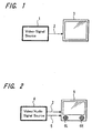
- the video data encoded according to the DVI standard may be transmitted from a video-signal source 1 to a display device 3 by connecting them using a cable 2 of the DVI standard.
- the video data and audio data are transmitted from a video/audio signal source 4 to a display device 6 including a speaker, it is required that the video data are transmitted through the cable 2 according to the DVI standard, and, furthermore, the audio data are transmitted through an audio signal cable 5 different from the cable 2.
- the image output from the video/audio signal source 4 may be displayed on the display device 6, and sounds may be output from speakers 6L, 6R installed in the display device 6.
- connection configuration becomes more complex.
- the number of cables to connect devices is preferably small.
- a data transmission technology using a bus line according to an IEEE (The Institute of Electrical and Electronics Engineers) 1394 standard, for example, may be applied to a technology for transmitting video data and audio data using one cable after multiplexing both the data.
- IEEE 1394 standard The Institute of Electrical and Electronics Engineers 1394 standard
- highly complex data processing is required for data transmission using the bus line according to the above IEEE1394 standard or the like, and therefore, extremely large-scale circuit configuration is required to perform encoding processing for transmission on a sending side, and to perform decoding processing of the data received through the bus line on a receiving side; and the cost may increase.
- video data and audio data are compressed and encoded to multiplex them in view of a transmission rate and so on. Therefore, there has been a disadvantage that the quality of picture may be degraded compared with that in the above described DVI standard in which the video data are digitalized in pixels to be transmitted.
- the object of the present invention is to multiplex audio data onto video data to favorably transmit the multiplexed data in a simple configuration.
- the first aspect of the present invention is a data transmission method comprising the steps of: dividing digital audio data having a predetermined packet structure into units including a predetermined number of bits; converting each unit of the divided digital audio data into specific data to be encoded; arranging the encoded data in blanking intervals of video data; and transmitting the digital audio data as well as the video data using a transmission line for the video data.
- audio data are multiplexed onto video data utilizing blanking intervals of the video data, and the video data and the audio data are simultaneously transmitted adopting an existing video-data transmission format such as the DVI standard.
- the digital audio data are favorably transmitted using a transmission line for the video data, while the existing configuration for transmitting video data is used without alterations.
- the second aspect of the present invention is that in the data transmission method according to the first aspect of the invention, the digital audio data having the packet structure include a parity code for audio data.
- error detection of the transmitted audio data can be performed by using the parity code on a receiving side.
- the third aspect of the present invention is that in the data transmission method according to the second aspect of the invention, data at a position where an error has been detected on decoding the encoded data are restored with operation using the parity code to correct the error, when the digital audio data transmitted on the transmission line is received.
- error correction of the audio data may be realized by simple processing.
- the fourth aspect of the present invention is a data transmission system for transmitting video data and digital audio data from a data sending device to a data receiving device, the data sending device in the data transmission system comprising: data division means for dividing digital audio data having a predetermined packet structure into units including a predetermined number of bits; encoding means for converting each unit of the digital audio data divided by the data division means into specific data to be encoded; and data transmission means for transmitting the data to a predetermined transmission line, after the data encoded by the encoding means are arranged in blanking intervals of the video data to be synthesized, and the data receiving device in the data transmission system comprising: separation means for separating the data arranged in the blanking intervals of the video data which are received through the transmission line; decoding means for decoding the encoded data separated by the separation means; and data assembly means for assembling the data decoded by the decoding means into the data with the original packet structure.
- a transmission system in which audio data are multiplexed onto video data utilizing blanking intervals of the video data, and the video data and the audio data are simultaneously transmitted adopting an existing video-data transmission format such as the DVI standard.
- the digital audio data are favorably transmitted using a transmission line for the video data, while an existing configuration for transmitting video data is used without alterations.
- the fifth aspect of the present invention is that in a data transmission system according to the fourth aspect of the invention, digital audio data having a packet structure, which are divided by the data dividing means of the data sending device, include a parity code for audio data, and the parity code is also transmitted to the data receiving device through the transmission line.
- the sixth aspect of the present invention is that in a data transmission system according to the fifth aspect of the invention, data at a position where an error is detected by the decoding means of the data receiving device are restored into the original data by the operation using the parity code to correct the error.
- the seventh aspect of the present invention is that in a data sending device for sending video data and digital audio data, the data sending device comprises: data division means for dividing the digital audio data having a predetermined packet structure into units including a predetermined number of bits; encoding means for converting each unit of the digital audio data divided by the data division means into specific data to be encoded; and data transmission means for transmitting the data to a predetermined transmission line, in which the data encoded by the encoding means are arranged in blanking intervals of the video data to be synthesized.
- the digital audio data are favorably transmitted using a transmission line for transmitting the video data, while an existing configuration for transmitting video data is used without alterations.
- the eighth aspect of the present invention is that in the data sending device according to the seventh invention, the digital audio data having the packet structure, which are divided by the data dividing means, include a parity code for audio data, and the parity code is also transmitted from the data sending device to the transmission line.
- error detection of the audio data transmitted from the sending device may be realized on the data receiving side using the parity code.
- the ninth aspect of the present invention is that in a data receiving device for receiving video data and digital audio data, the receiving device comprises: separation means for separating data, which are arranged in blanking intervals of the video data, received through a predetermined transmission line; decoding means for decoding the predetermined encoded data separated by the separation means; and data assembly means for assembling the data decoded by the decoding means into the data with the original packet structure.
- the digital audio data are favorably transmitted using a transmission line for transmitting the video data, while an existing configuration for transmitting video data is used without alterations.
- the tenth aspect of the present invention is that in the data receiving device according to the ninth aspect of the invention, the data received through the transmission line include a parity code for audio data to be transmitted; and the data at a position where an error is detected by the decoding means are restored into the original data by operation using the parity code to correct the error.
- error detection of the received audio data using the parity code can be realized, and it enables audio reproduction without an error.
- FIGS. 3 to 11 an embodiment of the present invention will be described.
- the invention is applied to a system in which video data output from a video/audio signal source such as a videotape recording/reproducing device, a video disk reproducing device, and a tuner are transmitted to a display device such as a monitor receiving unit and a television receiver.
- a device having an audio outputting function is used as the display device, and video data and audio data are transmitted from a video/audio signal source using one cable.
- the cable of DVI (Digital Visual Interface) standard is used to transmit the data.
- FIG. 3 is a view showing a general configuration of a transmission system according to this embodiment. It is configured that a video/audio signal source 10 is connected to a display device 20 including a speaker, using a DVI cable 2 by which video data and audio data are transmitted. Connector units of the video/audio signal source 10 and the display device 20, to which the DVI cable 2 is connected, are constituted to have, for example, a 24-pin connector respectively, and twenty-four pins of each connector of the device 10 and device 20 are individually connected through the cable 2.
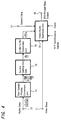
- FIG. 4 shows a configuration for processing in which the video/audio signal source 10 functions as a sending device by which video data and audio data are transmitted to the DVI standard cable.
- the video data encoded according to the DVI standard are supplied from a video processing unit (not shown) of the device 10 to a video-data input unit 11.
- the video data obtained in the video-data input unit 11 are supplied to an video/audio synthesis unit 12; synthesis processing by which the audio data are multiplexed on the video data is performed in the synthesis unit 12; and the synthesized data are supplied to a DVI-format-data output unit 18, from which the data are transmitted to the DVI cable connected to the device 10.
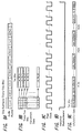
- FIGS. 6A to 6E a configuration in which video data are transmitted according to the DVI format will be described.
- B data blue data
- G data green data
- R data red data
- FIG. 6C The data on each channel are assumed to be data in which eight bits are used to represent each pixel, and data of three channels become data of twenty-four bits in total for one pixel.
- 8-bit data are converted into 10-bit data for transmission.
- the pixel data of each channel are transmitted in synchronization with a pixel clock shown in FIG. 6D.
- FIG. 6E is a view showing details of bit data on each channel, and 10-bit pixel data [0, 1, 2 .... 9] on each channel are transmitted in synchronization with the pixel clock.
- the pixel data on each channel are not transmitted during horizontal blanking intervals and vertical blanking intervals.
- data defined as a horizontal synchronization signal HSYNC are transmitted during the horizontal blanking intervals
- data defined as a vertical synchronization signal VSYNC are transmitted during the vertical blanking intervals.
- two control data CTL0 data and CTL1 data
- two control data CTL2 data and CTL3 data
- control data CTL0, CTL1, CTL2, and CTL3 are represented as control data C0, C1, C2, and C3, respectively.
- Respective control data C0, C1, C2, and C3, which are 2-bit data, are converted into 10-bit data to be arranged in the blanking intervals of respective channels.
- 2-bit data of 1-bit control data C0 and 1-bit control data C1 are obtained; the 2-bit data are converted into 10-bit data with a specific pattern; and the converted 10-bit data are arranged in the blanking intervals.
- FIG. 7 there are four kinds of combinations [0 0], [0 1], [1 0], and [1 1] as the combination of 2-bit data including the control data C0, C1, and 10-bit CTL code is assigned to each combination as shown in FIG. 7. Therefore, data other than the four kinds of 10-bit data are not transmitted on the G data channel during the blanking intervals.
- the control data C2, C3 transmitted on the R data channel are similarly processed.
- the audio data obtained in the audio data input unit 13 are the audio data made into packets according to an IEC (International Electrotechnical Commission) 60958 method.
- one packet (one subframe) comprises thirty-two bits; a preamble is arranged in the first four bits; and one sample of audio data (audio sample word) is arranged in the subsequent 24-bit segment, as shown in FIG. 8A.
- data with the number of bits being less than twenty-four are arranged as one sample.
- a sub-code is arranged in the last four bits.
- a parity bit V, a user data bit U, a channel status bit C, and a parity bit P are arranged as the sub-code in one packet.
- the parity bit P of one bit is a code for executing parity check on the audio data, and it may be judged whether there is an error in the packet of the audio data by the parity check through operation using the parity code. However, only the presence of the error is judged by the data of the parity bit P, and the error may not be corrected.
- a 4-bit segment following the 4-bit preamble is assumed to be an auxiliary data segment, and the segment in which the audio sample word is arranged is set to twenty bits, as shown in FIG. 8B.
- one frame comprises two packets in total, that is, one packet of the audio data for a left channel, and one packet of the audio data for a right channel, and data of sixty-four bits of two packets are transmitted as one unit.
- the audio data having the packet structure obtained in the audio data input unit 13 are constituted to be made into a data array in which thirty-two 2-bit data each comprised of one bit from each of the arranged two packets are obtained, as the audio data of sixty-four bits for two packets (one frame) being one unit, and then the thirty-two 2-bit data are supplied to a symbol cutting-out unit 15.
- the supplied thirty-two 2-bit data are sequentially cut-out one by one (that is, every two bits) to be output.
- the 2-bit data cut-out in the symbol cutting-out unit 15 are supplied to a 2-bit/10-bit conversion unit 16.
- Conversion processing into the 10-bit data in the conversion unit 16 is performed in a similar manner to the conversion processing of the 2-bit data of C0 and C1 into the 10-bit data, as described in FIG. 7. Specifically, the 2-bit data are converted into any one of four kinds of the CTL code shown in FIG. 7.
- the converted 10-bit data are supplied to the video/audio synthesis unit 12, in which the audio data are multiplexed onto the video data by arranging the 10-bit data in the horizontal blanking intervals on the G data channel.
- the audio data are transmitted as the control data C0, C1 which are transmitted during the horizontal blanking intervals on the G data channel.
- the details of data processing in actual practice will be later described in the description on operations.
- the audio data of eight subframes (four frames) at the maximum may be transmitted during one horizontal blanking interval in this embodiment.
- control data supplied from a control-data input unit 17 to the video/audio synthesis unit 12 are converted into 10-bit data as the control data C2 and C3 to be arranged in the horizontal blanking intervals on the R data channel. Further, data necessary for output according to the DVI format, such as the horizontal and the vertical synchronization signals and a pixel clock, are supplied to the video/audio synthesis unit 12.
- FIG. 5 shows a configuration for the processing in which the display device 20 functions as a device receiving the video data and the audio data transmitted through the DVI cable.
- the data transmitted through the DVI cable connected to the device 10 are obtained in a DVI format data input unit 21.
- the data obtained in the input unit 21 are supplied to a video/audio separation unit 22, in which each of the data (audio data and control data) arranged in the blanking intervals is separated from the video data.
- the video data from which the above described data have been separated in the video/audio separation unit 22 are supplied through a video data output unit 23 to a video processing unit (not shown) in the display device 20 to be processed for display.
- the control data (control data C2, C3 multiplexed on the blanking intervals of the R data channel) separated in the video/audio separation unit 22 are supplied to a controller (not shown) of the display device 20 through a control data output unit 24.
- the audio data (data transmitted as the control data C0, C1) which have been separated from the horizontal blanking intervals on the G data channel in the video/audio separation unit 22 are supplied to a 10-bit/2-bit conversion unit 25.
- the 10-bit/2-bit conversion unit 25 decoding processing by which the 10-bit CTL code shown in FIG. 7 are converted into the 2-bit data C0, C1 is performed.
- the 2-bit unit data converted in the 10-bit/2-bit conversion unit 25 are supplied to a packet assembly unit 26, in which thirty-two supplied 2-bit data are collected to be processed for assembling two packets (two subframes: one frame). Further, it is configured that the error detection data output from the 10-bit/2-bit conversion unit 25 are supplied to the packet assembly unit 26, and an error flag based on the error detection data is set to each bit of the packets assembled in the packet assembly unit 26. The data at a bit position to which the error flag has been set are missing data.
- the packet data assembled in the packet assembly unit 26 are supplied to an error correction unit 27 and a parity extraction unit 28.
- a parity bit in the supplied packet data is extracted, and the extracted parity bit is supplied to the error correction unit 27.
- error-correction processing in which the missing data are determined based on the operation according to parity check using the parity bit is performed in the error correction unit 27. Since the parity bit comprises one bit per one packet in this embodiment, it is possible to restore missing data up to one bit per one packet. However, when there are missing data of two or more bits per one packet, the error may not be corrected by the operation using the parity check.
- the two-subframe-unit packet data on which the error-correction processing has been performed are supplied through an audio data output unit 29 to an audio processing unit (not shown) in the display device 20 to be processed and output from speakers 20L and 20R shown in FIG. 3.
- FIGS. 9A to 9E are views showing a state in which audio data packets according to the IEC 60958 standard are arranged in the horizontal blanking intervals on the sending side (the video/audio signal source 10 in this embodiment).
- the audio data packet according to the standard has a constitution in which one subframe corresponding to one packet includes thirty-two bits, and a packet of the left channel (Lch) and a packet of the right channel (Rch) are alternately arranged to be supplied.
- packets A 1 , A 3 , A 5 .... with a subscript of an odd number are subframes for the left channel
- packets A 2 , A 4 , A 6 with a subscript of an even number are subframes for the right channel.
- the 10-bit data obtained as described above are arranged in the horizontal blanking interval shown by a horizontal synchronization signal of FIG. 9D on a specific channel (G data channel in this embodiment) of the video data in synchronization with the pixel clock shown in FIG. 9C.
- FIG. 9E shows a state in the horizontal blanking interval of the channel in which the audio data are arranged as the control data C0, C1.
- the above-described 10-bit data [A 1 , A 2 0], [A 1, A 2 1], [A 1 , A 2 2] .... [A 1 A 2 31] are sequentially output, being synchronous with the pixel clock.
- audio data in each packet are sequentially transmitted in the horizontal blanking interval.
- the 0-data that is, 10-bit data comprising C0 and C1 both of which are 0
- the remaining time of the horizontal blanking interval are continuously arranged in the remaining time of the horizontal blanking interval.
- FIG. 10 shows the example of six subframes (three frames) being arranged (FIG. 10B) in one horizontal blanking interval shown by the horizontal synchronization signal of FIG. 10A, and the example of eight subframes (four frames) are arranged (FIG. 10C) in one horizontal blanking interval of FIG. 10A.
- FIG. 10B shows the example of six subframes (three frames) being arranged (FIG. 10B) in one horizontal blanking interval shown by the horizontal synchronization signal of FIG. 10A
- FIG. 10C shows the example of eight subframes (four frames) in one horizontal blanking interval of FIG. 10A.
- FIG. 10B shows the example of six subframes (three frames) being arranged (FIG. 10B) in one horizontal blanking interval shown by the horizontal synchronization signal of FIG. 10A
- FIG. 10C shows the example of eight subframes (four frames) in one horizontal blanking interval of FIG. 10A.
- FIG. 10B shows the example of six subframes (three frames) being arranged
- the two pieces of processing are combined such that the processing by which the audio data of four frames (four samples per one channel: eight subframes in total) are sent in one horizontal line is executed once in tens of times, when processing by which the audio data of three frames (three samples per one channel: six subframes in total) are sent in one horizontal line is executed, thereby the audio being transmitted as well as the video without delay.
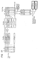
- FIG. 11 shows an example in which two subframes A 1 , A 2 are transmitted. Specifically, as shown in the left end of FIG. 11, after subframes A 1 , A 2 both of which respectively comprise 32 bits are converted into 10-bit data [A 1 , A 2 0], [A 1 , A 2 1], [A 1 , A 2 2] .... [A 1 , A 2 31] by every 2-bit data at each bit position, the converted 10-bit data are sequentially transmitted, using the DVI cable during the horizontal blanking interval.
- the missing data are restored by operation processing in the error correction unit 27.
- the missing data is judged by separately performing the operation using a parity bit on each of the subframes A 1 , A 2 .
- Various kinds of known methods which have been used for encoding digital data may be applied to a method for setting the parity bit. For example, setting a parity bit so that all of the thirty-two bits in one subframe, to which the parity bit is respectively added, become even number as a result, it is possible to judge whether the missing data are 1-data or 0-data by adding thirty-one bits other than the missing data. Consequently, after error correction of a subframe is performed in the error correction unit 27, the corrected subframe may be obtained in the audio data output unit 29.
- the audio data may be easily and favorably transmitted using the configuration for transmitting the video data.
- using a system for transmitting existing digital video data according to the DVI standard enables transmission of the audio data as well as the video data on the same signal cable.
- the audio data are configured to be transmitted in horizontal blanking intervals of the video data, there is no need to change the conventional DVI standard with respect to the configuration for the processing of transmitting the video data, and processing blocks prepared for the DVI standard of the video data may be used at both of the sending and receiving sides without any alterations.
- packet data according to the IEC 60958 method which has been widely used as a data transmission standard for transmitting digital audio data, are transmitted as the audio data without alterations, error correction using a parity bit which has been previously prepared in the packet according to the above method is performed to realize favorable transmission with less errors, when there is a transmission error in the packet data according to the above described method.
- digital audio data of two channels are configured to be transmitted in the above-described embodiment
- the present invention may also be applied to a case where digital audio data of one channel are transmitted, or to a case in which digital audio data of three or more channels are transmitted.
- the CTL2 and CTL3 portions of horizontal blanking intervals on the R data channel shown in FIG. 6 may be used for transmitting the audio data.
- packets in which digital audio data at a certain sample rate are arranged are transmitted, packets in which digital audio data compressed to be encoded according to a predetermined method (such as the ATRAC method and the MP3 method) are arranged may be transmitted.
- a predetermined method such as the ATRAC method and the MP3 method
- the audio data is multiplexed onto the video data to be transmitted using a transmission line according to the DVI standard
- other standards for transmitting the video data may be applied.
- a wireless transmission, as well as a transmission line by wire connection, may be used in those cases.
- audio data are multiplexed onto video data using blanking intervals of the video data, to simultaneously transmit the audio data as well as the video data using a transmission line for transmitting the video data by adopting an existing video-data transmission format such as the DVI standard, and as a result, the digital audio data are favorably transmitted, while an existing configuration for transmitting video data is used without any alterations.
- the digital audio data having a packet structure include the parity code for the audio data, thereby enabling the receiving side to perform error detection of audio data which are transmitted, using the parity code.
Landscapes
- Engineering & Computer Science (AREA)
- Multimedia (AREA)
- Signal Processing (AREA)
- Power Engineering (AREA)
- Computer Networks & Wireless Communication (AREA)
- Computational Linguistics (AREA)
- Health & Medical Sciences (AREA)
- Audiology, Speech & Language Pathology (AREA)
- Human Computer Interaction (AREA)
- Physics & Mathematics (AREA)
- Acoustics & Sound (AREA)
- Television Systems (AREA)
- Compression Or Coding Systems Of Tv Signals (AREA)
- Time-Division Multiplex Systems (AREA)
- Error Detection And Correction (AREA)
- Detection And Prevention Of Errors In Transmission (AREA)
Abstract
Description
Claims (10)
- A data transmission method comprising the steps of:dividing digital audio data having a predetermined packet structure into units including a predetermined number of bits;converting each unit of the divided digital audio data into specific data to be encoded;arranging the encoded data in blanking intervals of video data; andtransmitting the digital audio data as well as the video data, using a transmission line of said video data.
- The data transmission method according to claim 1, wherein
said digital audio data having the packet structure include a parity code for audio data. - The data transmission method according to claim 2, wherein
data at a position where an error is detected on decoding said encoded data are restored by operation using said parity code to correct the error, when the digital audio data transmitted on said transmission line are received. - In a data transmission system for transmitting video data and digital audio data from a data sending device to a data receiving device, the data transmission system comprising:said data sending device including:data division means for dividing digital audio data having a predetermined packet structure into units including a predetermined number of bits;encoding means for converting each unit of the digital audio data divided by said data division means into specific data to be encoded; anddata transmission means for arranging the data encoded by said encoding means in blanking intervals of the video data to be synthesized and transmitting the synthesized data to a predetermined line, andsaid data receiving device including:separation means for separating the data arranged in the blanking intervals of the video data which are received through said transmission line;decoding means for decoding said encoded data separated by said separation means; anddata assembly means for assembling the data decoded by said decoding means into the data with the original packet structure.
- The data transmission system according to claim 4, wherein
the digital audio data having a packet structure, which are divided by the data dividing means of said data sending device, include a parity code for audio data, and the parity code is also transmitted to said data receiving device through said transmission line. - The data transmission system according to claim 5, wherein
data at a position where an error is detected by the decoding means of said data receiving device are restored into the original data by operation using the parity code to correct the error. - In a data sending device for sending video data and digital audio data, the data sending device comprising:data division means for dividing the digital audio data having a predetermined packet structure into units including a predetermined number of bits;encoding means for converting each unit of the digital audio data divided by said data division means into specific data to be encoded; anddata transmission means for arranging the data encoded by said encoding means in blanking intervals of the video data to be synthesized and transmitting the synthesized data to a predetermined line.
- The data sending device according to claim 7, wherein
the digital audio data having a packet structure, which are divided by said data dividing means, include a parity code for audio data, and the parity code is also transmitted from said data transmission means to said transmission line. - In a data receiving device for receiving video data and digital audio data, the data receiving device comprising:separation means for separating data which are arranged in blanking intervals of video data received through a predetermined transmission line;decoding means for decoding the data separated by said separation means, which have been encoded by a predetermined code; anddata assembly means for assembling the data decoded by said decoding means into the data with the original packet structure.
- The data receiving device according to claim 9, wherein
the data received through said transmission line include a parity code for audio data to be transmitted; and
data at a position where an error is detected by said decoding means are restored into the original data by operation using said parity code to correct the error.
Priority Applications (1)
| Application Number | Priority Date | Filing Date | Title |
|---|---|---|---|
| EP12183580A EP2533532A1 (en) | 2001-01-30 | 2002-01-29 | Device for multiplexing digital audio data during blanking intervals of video signals |
Applications Claiming Priority (3)
| Application Number | Priority Date | Filing Date | Title |
|---|---|---|---|
| JP2001002209 | 2001-01-30 | ||
| JP2001022094A JP3648685B2 (en) | 2001-01-30 | 2001-01-30 | Data transmission method and data transmission apparatus |
| PCT/JP2002/000664 WO2002062064A1 (en) | 2001-01-30 | 2002-01-29 | Transmission method, transmission system, transmission device and reception device |
Publications (2)
| Publication Number | Publication Date |
|---|---|
| EP1357751A1 true EP1357751A1 (en) | 2003-10-29 |
| EP1357751A4 EP1357751A4 (en) | 2010-05-26 |
Family
ID=18887550
Family Applications (2)
| Application Number | Title | Priority Date | Filing Date |
|---|---|---|---|
| EP02710374A Withdrawn EP1357751A4 (en) | 2001-01-30 | 2002-01-29 | TRANSMISSION METHOD, TRANSMISSION SYSTEM, TRANSMISSION DEVICE, AND RECEPTION DEVICE |
| EP12183580A Withdrawn EP2533532A1 (en) | 2001-01-30 | 2002-01-29 | Device for multiplexing digital audio data during blanking intervals of video signals |
Family Applications After (1)
| Application Number | Title | Priority Date | Filing Date |
|---|---|---|---|
| EP12183580A Withdrawn EP2533532A1 (en) | 2001-01-30 | 2002-01-29 | Device for multiplexing digital audio data during blanking intervals of video signals |
Country Status (5)
| Country | Link |
|---|---|
| US (2) | US7129991B2 (en) |
| EP (2) | EP1357751A4 (en) |
| JP (1) | JP3648685B2 (en) |
| KR (2) | KR100809676B1 (en) |
| WO (1) | WO2002062064A1 (en) |
Families Citing this family (21)
| Publication number | Priority date | Publication date | Assignee | Title |
|---|---|---|---|---|
| KR100586669B1 (en) | 2003-08-27 | 2006-06-08 | 닛뽕빅터 가부시키가이샤 | Transmission system |
| KR100654834B1 (en) * | 2005-01-12 | 2006-12-08 | 삼성전자주식회사 | Host device, display device and display system |
| US7671873B1 (en) * | 2005-08-11 | 2010-03-02 | Matrox Electronics Systems, Ltd. | Systems for and methods of processing signals in a graphics format |
| DE102006052214B3 (en) * | 2006-11-06 | 2008-02-28 | Siemens Ag | Image playback system has image source, which supplies digital video signals by line pair and communication signal, where communication signal denotes transmission of configuration data or modified data |
| KR100819439B1 (en) * | 2007-08-23 | 2008-04-04 | 주식회사 디에이텍 | Multimedia signal serial transmission device |
| CN101835019A (en) | 2007-09-13 | 2010-09-15 | 株式会社日立制作所 | Transmission method, transmission device, imaging device and display device |
| JP2009100246A (en) | 2007-10-17 | 2009-05-07 | Hitachi Ltd | Display device |
| JP4605231B2 (en) | 2008-02-15 | 2011-01-05 | ソニー株式会社 | Electronic device, display system, transmission method and display method |
| JP4743250B2 (en) | 2008-09-30 | 2011-08-10 | ソニー株式会社 | Transmission apparatus, transmission method and program |
| WO2011041734A1 (en) * | 2009-10-02 | 2011-04-07 | Gabriele Sartori | System and method for a thin-client terminal system supporting usb devices |
| CN102131119A (en) * | 2010-01-14 | 2011-07-20 | 索尼公司 | Information processing apparatus, information processing method, and program |
| WO2011118135A1 (en) * | 2010-03-25 | 2011-09-29 | パナソニック株式会社 | Transmitter apparatus, receiver apparatus, transmission method and reception method |
| WO2013122387A1 (en) | 2012-02-15 | 2013-08-22 | Samsung Electronics Co., Ltd. | Data transmitting apparatus, data receiving apparatus, data transceiving system, data transmitting method, and data receiving method |
| WO2013122385A1 (en) | 2012-02-15 | 2013-08-22 | Samsung Electronics Co., Ltd. | Data transmitting apparatus, data receiving apparatus, data transreceiving system, data transmitting method, data receiving method and data transreceiving method |
| WO2013122386A1 (en) * | 2012-02-15 | 2013-08-22 | Samsung Electronics Co., Ltd. | Data transmitting apparatus, data receiving apparatus, data transreceiving system, data transmitting method, data receiving method and data transreceiving method |
| WO2014045502A1 (en) * | 2012-09-21 | 2014-03-27 | パナソニック株式会社 | Transmission system |
| JP6195444B2 (en) * | 2013-01-18 | 2017-09-13 | サターン ライセンシング エルエルシーSaturn Licensing LLC | Source device, communication system, source device control method, and sink device control method |
| CN104660950B (en) * | 2015-02-14 | 2019-05-14 | 京东方科技集团股份有限公司 | Video controller, display device, playback controller, and display system |
| KR20170059757A (en) * | 2015-11-23 | 2017-05-31 | 삼성전자주식회사 | Video signal transmission device, method for video signal transmission thereof, video signal reception device and method for video signal reception thereof |
| CN105577671B (en) * | 2015-12-30 | 2019-02-01 | 上海芃矽半导体技术有限公司 | The transmission method and Transmission system of audio signal and vision signal |
| US11411989B2 (en) * | 2017-04-27 | 2022-08-09 | Arxan Technologies, Inc. | Transmitting surreptitious data on an existing communication channel |
Family Cites Families (16)
| Publication number | Priority date | Publication date | Assignee | Title |
|---|---|---|---|---|
| JPS58190147A (en) * | 1982-04-30 | 1983-11-07 | Sony Corp | Data transmitting method |
| JPS60174958A (en) | 1984-02-21 | 1985-09-09 | Toshiba Corp | Phase decision apparatus |
| JPH048979A (en) | 1990-04-26 | 1992-01-13 | Hitachi Cable Ltd | Fire protection method for wall or floor penetrations |
| JP3135308B2 (en) | 1991-09-03 | 2001-02-13 | 株式会社日立製作所 | Digital video / audio signal transmission method and digital audio signal reproduction method |
| JPH0680556A (en) * | 1992-09-01 | 1994-03-22 | Kao Corp | Bath agent composition |
| JP3411674B2 (en) * | 1994-06-27 | 2003-06-03 | ペンタックス株式会社 | Aperture device of light source device for endoscope |
| JPH0846956A (en) | 1994-08-02 | 1996-02-16 | Matsushita Electric Ind Co Ltd | Packet extractor |
| JPH08154048A (en) * | 1994-09-29 | 1996-06-11 | Kawasaki Steel Corp | Semiconductor integrated circuit |
| JPH08154084A (en) * | 1994-11-28 | 1996-06-11 | Matsushita Electric Ind Co Ltd | Digital transmission / reception method and apparatus |
| KR100188084B1 (en) * | 1995-05-12 | 1999-06-01 | 김광호 | Apparatus and method for transmitting audio data using video signal line |
| US5751366A (en) * | 1995-08-31 | 1998-05-12 | Lucent Technologies Inc. | Inclusion of audio signal within video signal |
| US5835498A (en) * | 1995-10-05 | 1998-11-10 | Silicon Image, Inc. | System and method for sending multiple data signals over a serial link |
| JP2768338B2 (en) | 1995-12-26 | 1998-06-25 | 日本電気株式会社 | Audio video interface circuit |
| US5761303A (en) * | 1995-12-28 | 1998-06-02 | At&T Corp | Inclusion of audio signal within video signal, at band edges |
| JPH11289522A (en) | 1998-04-01 | 1999-10-19 | Sharp Corp | Television data broadcast receiver |
| JP6080556B2 (en) * | 2013-01-11 | 2017-02-15 | 名古屋電機工業株式会社 | Inspection image generation apparatus, inspection image generation method, and inspection image generation program |
-
2001
- 2001-01-30 JP JP2001022094A patent/JP3648685B2/en not_active Expired - Lifetime
-
2002
- 2002-01-29 KR KR1020077002070A patent/KR100809676B1/en not_active Expired - Lifetime
- 2002-01-29 US US10/240,156 patent/US7129991B2/en not_active Expired - Lifetime
- 2002-01-29 EP EP02710374A patent/EP1357751A4/en not_active Withdrawn
- 2002-01-29 EP EP12183580A patent/EP2533532A1/en not_active Withdrawn
- 2002-01-29 WO PCT/JP2002/000664 patent/WO2002062064A1/en not_active Ceased
- 2002-01-29 KR KR1020027011296A patent/KR100866151B1/en not_active Expired - Lifetime
-
2006
- 2006-07-19 US US11/489,175 patent/US7714934B2/en not_active Expired - Lifetime
Also Published As
| Publication number | Publication date |
|---|---|
| KR100866151B1 (en) | 2008-10-30 |
| US20030169370A1 (en) | 2003-09-11 |
| US7129991B2 (en) | 2006-10-31 |
| EP2533532A1 (en) | 2012-12-12 |
| US7714934B2 (en) | 2010-05-11 |
| US20060285012A1 (en) | 2006-12-21 |
| KR20070029825A (en) | 2007-03-14 |
| WO2002062064A1 (en) | 2002-08-08 |
| EP1357751A4 (en) | 2010-05-26 |
| JP2002232377A (en) | 2002-08-16 |
| JP3648685B2 (en) | 2005-05-18 |
| KR20020091104A (en) | 2002-12-05 |
| KR100809676B1 (en) | 2008-03-07 |
Similar Documents
| Publication | Publication Date | Title |
|---|---|---|
| US7714934B2 (en) | Transmission method, transmission system, sending device and reception device | |
| EP1381235B1 (en) | Data transmitting method, data receiving method, data transmitting device and data receiving device | |
| CN101076130B (en) | Communication method and system, transmiting method and equipment, receiving method and equipment | |
| US8942259B2 (en) | Digital visual interface with audio and auxiliary data | |
| EP1429555B1 (en) | Data transmission device and data reception device | |
| US8503490B2 (en) | Information processing apparatus, information processing method, and program | |
| EP1326444B1 (en) | Signal transmitter and signal receiver | |
| CN101132506B (en) | Video receiving device and video receiving method | |
| JP2007311928A (en) | Transmission method, transmission system, transmission method, transmission device, reception method, and reception device | |
| JP4303166B2 (en) | Data receiving apparatus, data receiving method, and data transmission system | |
| HK1061494A (en) | Transmission method, transmission system, transmission device and reception device | |
| JP4483457B2 (en) | Transmission system | |
| CN100342715C (en) | High-definition multimedia interface branch apparatus | |
| JP3964880B2 (en) | Data receiving method, data receiving apparatus, digital signal transmission system, and data transmitting / receiving method | |
| US20080084502A1 (en) | Method and apparatus for transmitting/receiving data | |
| JP3982390B2 (en) | Data transmission method and apparatus | |
| WO2023171357A1 (en) | Signal transmission device, signal transmission method, signal reception device, signal reception method, and program | |
| CN114071031A (en) | A kind of multi-channel video superposition and switching method and device | |
| JP2003333553A (en) | Video signal converting method, video signal converting apparatus, and video signal transmission method |
Legal Events
| Date | Code | Title | Description |
|---|---|---|---|
| PUAI | Public reference made under article 153(3) epc to a published international application that has entered the european phase |
Free format text: ORIGINAL CODE: 0009012 |
|
| 17P | Request for examination filed |
Effective date: 20021004 |
|
| AK | Designated contracting states |
Kind code of ref document: A1 Designated state(s): AT BE CH CY DE DK ES FI FR GB GR IE IT LI LU MC NL PT SE TR |
|
| REG | Reference to a national code |
Ref country code: HK Ref legal event code: DE Ref document number: 1061494 Country of ref document: HK |
|
| RAP1 | Party data changed (applicant data changed or rights of an application transferred) |
Owner name: SONY CORPORATION Owner name: PANASONIC CORPORATION |
|
| A4 | Supplementary search report drawn up and despatched |
Effective date: 20100422 |
|
| 17Q | First examination report despatched |
Effective date: 20091013 |
|
| R17C | First examination report despatched (corrected) |
Effective date: 20100913 |
|
| STAA | Information on the status of an ep patent application or granted ep patent |
Free format text: STATUS: THE APPLICATION IS DEEMED TO BE WITHDRAWN |
|
| 18D | Application deemed to be withdrawn |
Effective date: 20130222 |
|
| REG | Reference to a national code |
Ref country code: HK Ref legal event code: WD Ref document number: 1061494 Country of ref document: HK |