EP1357256B1 - An internal combustion engine with an improved distribution control device - Google Patents
An internal combustion engine with an improved distribution control device Download PDFInfo
- Publication number
- EP1357256B1 EP1357256B1 EP03009446A EP03009446A EP1357256B1 EP 1357256 B1 EP1357256 B1 EP 1357256B1 EP 03009446 A EP03009446 A EP 03009446A EP 03009446 A EP03009446 A EP 03009446A EP 1357256 B1 EP1357256 B1 EP 1357256B1
- Authority
- EP
- European Patent Office
- Prior art keywords
- shaft
- engine
- drive shaft
- block
- auxiliary
- Prior art date
- Legal status (The legal status is an assumption and is not a legal conclusion. Google has not performed a legal analysis and makes no representation as to the accuracy of the status listed.)
- Expired - Lifetime
Links
Images

Classifications
-
- F—MECHANICAL ENGINEERING; LIGHTING; HEATING; WEAPONS; BLASTING
- F01—MACHINES OR ENGINES IN GENERAL; ENGINE PLANTS IN GENERAL; STEAM ENGINES
- F01L—CYCLICALLY OPERATING VALVES FOR MACHINES OR ENGINES
- F01L1/00—Valve-gear or valve arrangements, e.g. lift-valve gear
- F01L1/02—Valve drive
- F01L1/022—Chain drive
-
- F—MECHANICAL ENGINEERING; LIGHTING; HEATING; WEAPONS; BLASTING
- F01—MACHINES OR ENGINES IN GENERAL; ENGINE PLANTS IN GENERAL; STEAM ENGINES
- F01L—CYCLICALLY OPERATING VALVES FOR MACHINES OR ENGINES
- F01L1/00—Valve-gear or valve arrangements, e.g. lift-valve gear
- F01L1/02—Valve drive
-
- F—MECHANICAL ENGINEERING; LIGHTING; HEATING; WEAPONS; BLASTING
- F01—MACHINES OR ENGINES IN GENERAL; ENGINE PLANTS IN GENERAL; STEAM ENGINES
- F01L—CYCLICALLY OPERATING VALVES FOR MACHINES OR ENGINES
- F01L1/00—Valve-gear or valve arrangements, e.g. lift-valve gear
- F01L1/02—Valve drive
- F01L1/024—Belt drive
-
- F—MECHANICAL ENGINEERING; LIGHTING; HEATING; WEAPONS; BLASTING
- F01—MACHINES OR ENGINES IN GENERAL; ENGINE PLANTS IN GENERAL; STEAM ENGINES
- F01L—CYCLICALLY OPERATING VALVES FOR MACHINES OR ENGINES
- F01L1/00—Valve-gear or valve arrangements, e.g. lift-valve gear
- F01L1/02—Valve drive
- F01L1/04—Valve drive by means of cams, camshafts, cam discs, eccentrics or the like
- F01L1/047—Camshafts
- F01L1/053—Camshafts overhead type
- F01L2001/0535—Single overhead camshafts [SOHC]
-
- F—MECHANICAL ENGINEERING; LIGHTING; HEATING; WEAPONS; BLASTING
- F01—MACHINES OR ENGINES IN GENERAL; ENGINE PLANTS IN GENERAL; STEAM ENGINES
- F01L—CYCLICALLY OPERATING VALVES FOR MACHINES OR ENGINES
- F01L1/00—Valve-gear or valve arrangements, e.g. lift-valve gear
- F01L1/02—Valve drive
- F01L1/04—Valve drive by means of cams, camshafts, cam discs, eccentrics or the like
- F01L1/047—Camshafts
- F01L1/053—Camshafts overhead type
- F01L2001/0537—Double overhead camshafts [DOHC]
Definitions
- the present invention relates to an internal combustion engine provided with at least one overhead camshaft and in particular, but not exclusively, to a diesel engine for a vehicle.
- a drive arrangement for engine comprising a block, a drive shaft, one overhead camshaft and a distribution control device for the rotational connection of the camshaft to the drive shaft in a phased manner;
- the distribution control device comprises a first transmission unit connecting the drive shaft to an intermediate shaft and provided with a first flexible transmission member, and a second transmission unit connecting the intermediate shaft to the camshaft and provided with a second flexible transmission member.
- the first transmission unit of the abovecited US Patent solution comprises an auxiliary shaft having an axis parallel to and alongside an axis of the drive shaft and adapted to drive an oil pump of the engine and geared transmission means connecting the drive shaft to the auxiliary shaft, the first flexible transmission member being interposed between the auxiliary shaft and the intermediate shaft.
- a problem raised by known engines of the type described briefly above relates to the bulk of the first and second transmissions at the front end of the engine, facing the radiator, and the resultant problems that this raises 'from the point of view of installing the water pump and the relative ducts for connection to the engine cooling circuit which should advantageously be installed in this area.
- the object of the present invention is to provide an internal combustion engine with an improved distribution control unit which makes it possible to remedy the problems described above.
- an internal combustion engine comprising a block, a drive shaft, at least one overhead camshaft and a distribution control device for the rotational connection of the camshaft to the drive shaft in a phased manner
- the distribution control device comprising a first transmission unit connecting the drive shaft to an intermediate shaft and provided with a first flexible transmission member, and a second transmission unit connecting the intermediate shaft to the camshaft and provided with a second flexible transmission member
- the first transmission unit comprising an auxiliary shaft having an axis parallel to and alongside an axis of the drive shaft and adapted to drive an auxiliary member of the engine, and geared transmission means connecting the drive shaft to the auxiliary shaft, the first flexible transmission member being interposed between the auxiliary shaft and the intermediate shaft
- said oil pump (24) is housed in a lateral recess (27) of said block (3), behind a housing (23) for said geared transmission means (20,21), and comprises an input shaft (25) coaxial with said auxiliary shaft (19); said axes (E,A)
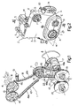
- a transmission device for controlling the distribution in an internal combustion engine 2, in particular a diesel engine, is shown overall by 1.
- the engine 2 comprises a block 3 formed by a cylinder block 4 defining a plurality of cylinders 5 and a sub-block 6 secured below the block 4 with which it meshes along a plane ⁇ .
- the engine 2 comprises a drive shaft 7 having an axis A contained in the plane ⁇ and supported between the cylinder block 4 and the sub-block 6, and a pair of overhead camshafts 10 ( Figs. 1 and 3 ), having axes B and C parallel with one another and with the axis A.
- the engine 2 further comprises an intermediate shaft 11 for driving a high pressure fuel pump 12 forming part of an injection unit (not shown) of the common rail type.
- the pump 12 is disposed on a flank 14 of the engine 2, in the vicinity of a front wall 13 of the block 3; the shaft 11 has an axis D parallel with the axes A, B and C.
- the device 1 ( Fig. 1 ) comprises a first transmission unit 17 connecting the drive shaft 7 to the intermediate shaft 11 and a second chain transmission unit 18 interposed between the intermediate shaft 11 and the two camshafts 10.
- the first transmission unit 17 comprises an auxiliary shaft 19 having an axis E parallel to the axis A of the drive shaft 7 and adjacent thereto, on the same side of the pump 12; the axis E preferably lies in the horizontal plane ⁇ passing through the axis A of the drive shaft 7.
- the first transmission unit 17 further comprises a pair of gears 20, 21 keyed on the drive shaft 7 and the auxiliary shaft 19 respectively, and connected together in order rotationally to connect the two shafts 7, 19, and a chain transmission 22 interposed between the auxiliary shaft 19 and the intermediate shaft 11.
- the gears 20, 21 are disposed in a box housing 23 provided immediately outside the front wall 13 of the engine 2, substantially symmetrical with respect to the plane ⁇ and formed in part by the cylinder block 4 and in part by the sub-block 6.
- the auxiliary shaft 19 moves an auxiliary member of the engine, in particular an oil pump 24 ( Figs. 3 and 4 ).
- the pump 24, of the geared type has an input shaft 25 of axis E on which a drive gear 26 is keyed.
- the pump 24 is advantageously housed in a lateral recess 27 of the block 3, open laterally for access to the pump itself, and disposed behind the housing 23.
- the auxiliary shaft 19 is advantageously formed in two parts, for technological and assembly reasons, and in particular comprises a tubular duct 30, mounted to pass through the housing 23 in an angularly free and axially fixed manner, and a spindle 31 which connects the duct 30 to the shaft 25 of the pump 24.
- the gear 21 is keyed on the duct 30, for instance by means of force fitting under heating.
- the spindle 31 is coupled to the duct 30 and to the shaft 25 of the pump 24 in a rotationally rigid and axially sliding manner by means of respective splined couplings 36, 37. In this way, it is possible axially to disengage the spindle 31 from the pump 24 and enable the dismantling of the latter without dismantling the engine 2.
- the position of the pump 24 is such as to enable an easy connection to the oil couple (not shown) and to the lubrication circuit of the engine 2 by means of channels 40 provided in the block 3.
- a sprocket 41 is also keyed on the duct 30 and forms part of the chain transmission 22, which sprocket further comprises a chain 42 and a driven wheel 43 keyed on a duct 44 rigidly connected to the intermediate shaft 11 of the pump 12 ( Fig. 3 ).
- the chain 42 of the chain transmission 22 is advantageously housed within the block 3 in the vicinity of the front wall 13.
- the second transmission unit 18 comprises, in a known manner, a drive sprocket 45 keyed on the intermediate shaft 11, a pair of wheels 46 keyed on the respective camshafts 10 and a single chain 47 in engagement with the sprocket 41 and both the wheels 46.
- the chains 42 and 47 are guided, in a conventional manner, by respective pairs of shoes 48a, 48b and 49a, 49b; one of the shoes (48a, 49a) of each pair, cooperating with the taut branch of the relative chain 42, 47 is fixed; the other (48b, 49b) cooperating with the return branch faces the flank 14 of the engine 2 and can move, under the thrust of a hydraulic tensioning member 50 and 51 respectively, for the recovery of play.
- the auxiliary shaft 19 is driven in rotation by the drive shaft 7 by means of the pair of gears 20, 21 and actuates the oil pump 24. Motion is transmitted via the chain 42 to the intermediate shaft 11, which also actuates the fuel pump 12, and from there to the camshafts 10 by means of the chain 47.
- the overall transmission ratio formed by the first transmission unit 17 and by the second transmission unit 18 is 1 ⁇ 2.
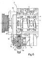
- a large zone 52 ( Fig. 6 ) is left free in a position adjacent to the front end of the cylinder block 4, in which auxiliary engine components may be readily installed, and in particular the cooling water pump (not shown) and the relative ducts for connection to the engine cooling circuit.
- the tensioning devices 50, 51 may be disposed towards the exterior of the engine 2 rather than on the side of the zone 52 as is conventionally the case. This provides the twofold advantage of avoiding the bulk of the tensioning devices 50, 51 in the zone 52 and improving their accessibility.
- auxiliary shaft 19 mounted between the cylinder block 4 and the sub-block 6 makes it possible to assemble the shaft itself and the oil pump 24 in a rapid and efficient way.
- the provision of the auxiliary shaft 19 in two telescopically sliding parts makes it possible to remove the oil pump 24 without dismantling the block 3.
- one or both of the chains 42, 47 may be replaced by toothed belts; in this case, the moving shoes and the relative hydraulic tensioning devices may be replaced by conventional mechanical idle pulley tensioning devices.
- the engine may be a controlled ignition rather than a diesel engine; the fuel pump may be an injection pump of conventional type; the auxiliary shaft 19 may directly control an auxiliary member at one of its front ends.
Landscapes
- Engineering & Computer Science (AREA)
- Mechanical Engineering (AREA)
- General Engineering & Computer Science (AREA)
- Valve-Gear Or Valve Arrangements (AREA)
- Gear Transmission (AREA)
- Ignition Installations For Internal Combustion Engines (AREA)
- Valve Device For Special Equipments (AREA)
Abstract
Description
- The present invention relates to an internal combustion engine provided with at least one overhead camshaft and in particular, but not exclusively, to a diesel engine for a vehicle.
- Internal combustion engines of the above-mentioned type are known in which the camshaft is synchronously driven by means of a first transmission, for instance a chain transmission, connecting the drive shaft to an intermediate return shaft, for instance the shaft of the fuel pump, and a second chain or toothed belt transmission connecting the intermediate shaft to the axle or the camshafts. An embodiment of this arrangement is disclosed in
EP-A-1 046 790 . - According to
US 5.154.144 , a drive arrangement for engine is disclosed comprising a block, a drive shaft, one overhead camshaft and a distribution control device for the rotational connection of the camshaft to the drive shaft in a phased manner; the distribution control device comprises a first transmission unit connecting the drive shaft to an intermediate shaft and provided with a first flexible transmission member, and a second transmission unit connecting the intermediate shaft to the camshaft and provided with a second flexible transmission member. - The first transmission unit of the abovecited US Patent solution comprises an auxiliary shaft having an axis parallel to and alongside an axis of the drive shaft and adapted to drive an oil pump of the engine and geared transmission means connecting the drive shaft to the auxiliary shaft, the first flexible transmission member being interposed between the auxiliary shaft and the intermediate shaft.
- A problem raised by known engines of the type described briefly above relates to the bulk of the first and second transmissions at the front end of the engine, facing the radiator, and the resultant problems that this raises 'from the point of view of installing the water pump and the relative ducts for connection to the engine cooling circuit which should advantageously be installed in this area.
- The object of the present invention is to provide an internal combustion engine with an improved distribution control unit which makes it possible to remedy the problems described above.
- According to the present invention, this object is achieved by an internal combustion engine comprising a block, a drive shaft, at least one overhead camshaft and a distribution control device for the rotational connection of the camshaft to the drive shaft in a phased manner, the distribution control device comprising a first transmission unit connecting the drive shaft to an intermediate shaft and provided with a first flexible transmission member, and a second transmission unit connecting the intermediate shaft to the camshaft and provided with a second flexible transmission member, the first transmission unit comprising an auxiliary shaft having an axis parallel to and alongside an axis of the drive shaft and adapted to drive an auxiliary member of the engine, and geared transmission means connecting the drive shaft to the auxiliary shaft, the first flexible transmission member being interposed between the auxiliary shaft and the intermediate shaft; characterized in that said oil pump (24) is housed in a lateral recess (27) of said block (3), behind a housing (23) for said geared transmission means (20,21), and comprises an input shaft (25) coaxial with said auxiliary shaft (19); said axes (E,A) lying on a horizontal plane (α).
- The present invention is described in further detail below with reference to an embodiment thereof, given by way of non-limiting example, with reference to the accompanying drawings, in which:
-
Fig. 1 is a perspective, diagrammatic and partial view of a distribution control unit of an internal combustion engine in accordance with the present invention; -
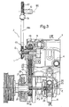
Fig. 2 is a perspective and partial view of the engine, with some parts removed for clarity; -
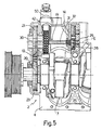
Fig. 3 is a section along the line III-III ofFig. 1 ; -
Fig. 4 is a section along the line IV-IV ofFig. 3 ; -
Fig. 5 is a section along the line V-V ofFig. 4 ; -
Fig. 6 is a top view, partly in section, of the block of the engine ofFig. 1 . - In
Figs. 1 to 3 , a transmission device for controlling the distribution in aninternal combustion engine 2, in particular a diesel engine, is shown overall by 1. - The
engine 2 comprises ablock 3 formed by acylinder block 4 defining a plurality ofcylinders 5 and asub-block 6 secured below theblock 4 with which it meshes along a plane α. - The
engine 2 comprises adrive shaft 7 having an axis A contained in the plane α and supported between thecylinder block 4 and thesub-block 6, and a pair of overhead camshafts 10 (Figs. 1 and3 ), having axes B and C parallel with one another and with the axis A. - The
engine 2 further comprises anintermediate shaft 11 for driving a highpressure fuel pump 12 forming part of an injection unit (not shown) of the common rail type. Thepump 12 is disposed on aflank 14 of theengine 2, in the vicinity of afront wall 13 of theblock 3; theshaft 11 has an axis D parallel with the axes A, B and C. - The device 1 (
Fig. 1 ) comprises afirst transmission unit 17 connecting thedrive shaft 7 to theintermediate shaft 11 and a secondchain transmission unit 18 interposed between theintermediate shaft 11 and the twocamshafts 10. - According to the present invention, the
first transmission unit 17 comprises anauxiliary shaft 19 having an axis E parallel to the axis A of thedrive shaft 7 and adjacent thereto, on the same side of thepump 12; the axis E preferably lies in the horizontal plane α passing through the axis A of thedrive shaft 7. - The
first transmission unit 17 further comprises a pair ofgears drive shaft 7 and theauxiliary shaft 19 respectively, and connected together in order rotationally to connect the twoshafts chain transmission 22 interposed between theauxiliary shaft 19 and theintermediate shaft 11. - In particular, the
gears 20, 21 (Figs. 3 and5 ) are disposed in abox housing 23 provided immediately outside thefront wall 13 of theengine 2, substantially symmetrical with respect to the plane α and formed in part by thecylinder block 4 and in part by thesub-block 6. - Advantageously, the
auxiliary shaft 19 moves an auxiliary member of the engine, in particular an oil pump 24 (Figs. 3 and4 ). Thepump 24, of the geared type, has aninput shaft 25 of axis E on which adrive gear 26 is keyed. - The
pump 24 is advantageously housed in alateral recess 27 of theblock 3, open laterally for access to the pump itself, and disposed behind thehousing 23. - The
auxiliary shaft 19 is advantageously formed in two parts, for technological and assembly reasons, and in particular comprises atubular duct 30, mounted to pass through thehousing 23 in an angularly free and axially fixed manner, and aspindle 31 which connects theduct 30 to theshaft 25 of thepump 24. - The
gear 21 is keyed on theduct 30, for instance by means of force fitting under heating. Thespindle 31 is coupled to theduct 30 and to theshaft 25 of thepump 24 in a rotationally rigid and axially sliding manner by means of respectivesplined couplings 36, 37. In this way, it is possible axially to disengage thespindle 31 from thepump 24 and enable the dismantling of the latter without dismantling theengine 2. - The position of the
pump 24 is such as to enable an easy connection to the oil couple (not shown) and to the lubrication circuit of theengine 2 by means ofchannels 40 provided in theblock 3. - A sprocket 41 is also keyed on the
duct 30 and forms part of thechain transmission 22, which sprocket further comprises achain 42 and a drivenwheel 43 keyed on a duct 44 rigidly connected to theintermediate shaft 11 of the pump 12 (Fig. 3 ). - The
chain 42 of thechain transmission 22 is advantageously housed within theblock 3 in the vicinity of thefront wall 13. - The
second transmission unit 18 comprises, in a known manner, adrive sprocket 45 keyed on theintermediate shaft 11, a pair ofwheels 46 keyed on therespective camshafts 10 and asingle chain 47 in engagement with the sprocket 41 and both thewheels 46. - The
chains shoes relative chain flank 14 of theengine 2 and can move, under the thrust of ahydraulic tensioning member - The operation of the device 1, already partly evident from the above description, is as follows.
- The
auxiliary shaft 19 is driven in rotation by thedrive shaft 7 by means of the pair ofgears oil pump 24. Motion is transmitted via thechain 42 to theintermediate shaft 11, which also actuates thefuel pump 12, and from there to thecamshafts 10 by means of thechain 47. The overall transmission ratio formed by thefirst transmission unit 17 and by thesecond transmission unit 18 is ½. - According to the present invention, by means of the use of an
auxiliary return shaft 19 in the first transmission unit, a large zone 52 (Fig. 6 ) is left free in a position adjacent to the front end of thecylinder block 4, in which auxiliary engine components may be readily installed, and in particular the cooling water pump (not shown) and the relative ducts for connection to the engine cooling circuit. - Since the return of motion by means of the
auxiliary shaft 19 causes, with the same direction of rotation of the drive shaft 7 (anticlockwise with respect toFig. 1 ), an inversion of the direction of rotation of thechains flank 14 of theengine 2. In this way, thetensioning devices engine 2 rather than on the side of thezone 52 as is conventionally the case. This provides the twofold advantage of avoiding the bulk of thetensioning devices zone 52 and improving their accessibility. - The use of an
auxiliary shaft 19 mounted between thecylinder block 4 and thesub-block 6 makes it possible to assemble the shaft itself and theoil pump 24 in a rapid and efficient way. The provision of theauxiliary shaft 19 in two telescopically sliding parts makes it possible to remove theoil pump 24 without dismantling theblock 3. - It will be appreciated that the
engine 2, and in particular the distribution control device 1, may be modified and varied without departing from the scope of protection of the claims. - In particular, one or both of the
chains auxiliary shaft 19 may directly control an auxiliary member at one of its front ends.
Claims (4)
- An internal combustion engine (2) comprising a block (3), a drive shaft (7), at least one overhead camshaft (10) and a distribution control device (1) for the rotational connection of the camshaft (10) to the drive shaft (7) in a phased manner, the distribution control device (1) comprising a first transmission unit (17) connecting the drive shaft (7) to an intermediate shaft (11) and provided with a first flexible transmission member (42), and a second transmission unit (18) connecting the intermediate shaft (11) to the camshaft (10) and provided with a second flexible transmission member (47), the first transmission unit (17) comprising an auxiliary shaft (19) having an axis (E) parallel to and alongside an axis (A) of the drive shaft (7) and adapted to drive an oil pump (24) of the engine (2), and geared transmission means (20, 21) connecting the drive shaft (7) to the auxiliary shaft (19), the first flexible transmission member (42) being interposed between the auxiliary shaft (19) and the intermediate shaft (11), characterized in that said oil pump (24) is housed in a lateral recess (27) of said block (3), behind a housing (23) for said geared transmission means (20,21), and comprises an input shaft (25) coaxial with said auxiliary shaft (19); said axes (E,A) lying on a horizontal plane (α).
- An engine as claimed in claim 1, characterised in that the block (3) comprises a cylinder block (4) and a sub-block (6) meshing together along said horizontal plane (α).
- An engine as claimed in claim 1 or 2, characterised in that the intermediate shaft (11) and the auxiliary shaft (19) are disposed in the vicinity of a flank of the engine (2).
- An engine as claimed in any one of the preceding claims, characterised in that it comprise a fuel pump (12) driven by the intermediate shaft (11).
Applications Claiming Priority (2)
| Application Number | Priority Date | Filing Date | Title |
|---|---|---|---|
| ITTO20020359 | 2002-04-26 | ||
| IT2002TO000359A ITTO20020359A1 (en) | 2002-04-26 | 2002-04-26 | ENDOTHERMAL ENGINE WITH A PERFECTED DISTRIBUTION CONTROL DEVICE. |
Publications (3)
| Publication Number | Publication Date |
|---|---|
| EP1357256A2 EP1357256A2 (en) | 2003-10-29 |
| EP1357256A3 EP1357256A3 (en) | 2004-01-21 |
| EP1357256B1 true EP1357256B1 (en) | 2010-11-24 |
Family
ID=27639032
Family Applications (1)
| Application Number | Title | Priority Date | Filing Date |
|---|---|---|---|
| EP03009446A Expired - Lifetime EP1357256B1 (en) | 2002-04-26 | 2003-04-25 | An internal combustion engine with an improved distribution control device |
Country Status (5)
| Country | Link |
|---|---|
| EP (1) | EP1357256B1 (en) |
| AT (1) | ATE489537T1 (en) |
| DE (1) | DE60335056D1 (en) |
| ES (1) | ES2356472T3 (en) |
| IT (1) | ITTO20020359A1 (en) |
Families Citing this family (2)
| Publication number | Priority date | Publication date | Assignee | Title |
|---|---|---|---|---|
| JP6248771B2 (en) * | 2014-04-14 | 2017-12-20 | スズキ株式会社 | Fuel injection system for diesel engine |
| DE112015000072B4 (en) * | 2014-04-04 | 2019-02-07 | Suzuki Motor Corporation | Fuel injector for diesel engine |
Family Cites Families (7)
| Publication number | Priority date | Publication date | Assignee | Title |
|---|---|---|---|---|
| FR2075754A5 (en) * | 1970-01-30 | 1971-10-08 | Alfieri Maserati Officin | |
| US4373240A (en) * | 1978-01-24 | 1983-02-15 | Castoe John H | Method for removing cam shaft sprocket |
| US5154144A (en) * | 1989-08-23 | 1992-10-13 | Yamaha Hatsudoki Kabushiki Kaisha | Camshaft drive arrangement for engine |
| DE4128432C2 (en) * | 1991-08-27 | 2000-04-27 | Deutz Ag | Wheel drive |
| JP3203144B2 (en) | 1995-03-22 | 2001-08-27 | シャープ株式会社 | Printing control device |
| JP3184438B2 (en) * | 1995-09-29 | 2001-07-09 | ヤマハ発動機株式会社 | Internal combustion engine |
| DE19816032A1 (en) * | 1997-05-03 | 1998-11-26 | Volkswagen Ag | Liquid-cooled internal combustion engine for vehicle |
-
2002
- 2002-04-26 IT IT2002TO000359A patent/ITTO20020359A1/en unknown
-
2003
- 2003-04-25 AT AT03009446T patent/ATE489537T1/en not_active IP Right Cessation
- 2003-04-25 DE DE60335056T patent/DE60335056D1/de not_active Expired - Lifetime
- 2003-04-25 EP EP03009446A patent/EP1357256B1/en not_active Expired - Lifetime
- 2003-04-25 ES ES03009446T patent/ES2356472T3/en not_active Expired - Lifetime
Also Published As
| Publication number | Publication date |
|---|---|
| DE60335056D1 (en) | 2011-01-05 |
| EP1357256A2 (en) | 2003-10-29 |
| ITTO20020359A0 (en) | 2002-04-26 |
| EP1357256A3 (en) | 2004-01-21 |
| ES2356472T3 (en) | 2011-04-08 |
| ITTO20020359A1 (en) | 2003-10-27 |
| ATE489537T1 (en) | 2010-12-15 |
Similar Documents
| Publication | Publication Date | Title |
|---|---|---|
| EP3436721B1 (en) | Gear backlash control for an opposed-piston engine | |
| EP1898125A3 (en) | Hydro-mechanical transmission apparatus and vehicle equipped with such a transmission apparatus | |
| WO1992009798A1 (en) | Combustion engine with variable compression ratio | |
| US6959682B2 (en) | Engine balancer with chain drive vibration isolation | |
| US8281891B2 (en) | Four wheel drive vehicle | |
| US9297125B2 (en) | Construction vehicle for preparation of a road surface | |
| US7070526B2 (en) | Accessory drive for driving a balance shaft | |
| CA2604120A1 (en) | Power transmission device | |
| JP4544088B2 (en) | Engine front structure | |
| US20120190492A1 (en) | Vehicle drive | |
| SK88794A3 (en) | Variable timing gear device | |
| US3939732A (en) | Power unit for vehicles incorporating an automatic stepless speed change gear | |
| EP1357256B1 (en) | An internal combustion engine with an improved distribution control device | |
| KR101514475B1 (en) | Variable transmission device for a vehicle | |
| US7159558B2 (en) | Engine having centralized mass | |
| US5761959A (en) | Transmission for driving vehicle accessories with floating input shaft | |
| RU2268167C2 (en) | Power train | |
| EP1370754A1 (en) | Drive for one or more engine accessories | |
| EP0522063B1 (en) | Belt transmission in an internal combustion engine for accessory device driving | |
| CN109252974B (en) | Mounting device for vehicle power train | |
| CA2340864A1 (en) | Tracked vehicle with shiftable lateral intermediate transmission | |
| JP2010059854A (en) | Internal combustion engine | |
| JPH0241301Y2 (en) | ||
| JPS63259124A (en) | Auxiliary machine driving device for engine | |
| US3393580A (en) | Power units for motor vehicles |
Legal Events
| Date | Code | Title | Description |
|---|---|---|---|
| PUAI | Public reference made under article 153(3) epc to a published international application that has entered the european phase |
Free format text: ORIGINAL CODE: 0009012 |
|
| AK | Designated contracting states |
Kind code of ref document: A2 Designated state(s): AT BE BG CH CY CZ DE DK EE ES FI FR GB GR HU IE IT LI LU MC NL PT RO SE SI SK TR |
|
| AX | Request for extension of the european patent |
Extension state: AL LT LV MK |
|
| PUAL | Search report despatched |
Free format text: ORIGINAL CODE: 0009013 |
|
| AK | Designated contracting states |
Kind code of ref document: A3 Designated state(s): AT BE BG CH CY CZ DE DK EE ES FI FR GB GR HU IE IT LI LU MC NL PT RO SE SI SK TR |
|
| AX | Request for extension of the european patent |
Extension state: AL LT LV MK |
|
| 17P | Request for examination filed |
Effective date: 20040715 |
|
| AKX | Designation fees paid |
Designated state(s): AT BE BG CH CY CZ DE DK EE ES FI FR GB GR HU IE IT LI LU MC NL PT RO SE SI SK TR |
|
| 17Q | First examination report despatched |
Effective date: 20041004 |
|
| 17Q | First examination report despatched |
Effective date: 20041004 |
|
| GRAP | Despatch of communication of intention to grant a patent |
Free format text: ORIGINAL CODE: EPIDOSNIGR1 |
|
| GRAS | Grant fee paid |
Free format text: ORIGINAL CODE: EPIDOSNIGR3 |
|
| GRAA | (expected) grant |
Free format text: ORIGINAL CODE: 0009210 |
|
| AK | Designated contracting states |
Kind code of ref document: B1 Designated state(s): AT BE BG CH CY CZ DE DK EE ES FI FR GB GR HU IE IT LI LU MC NL PT RO SE SI SK TR |
|
| REG | Reference to a national code |
Ref country code: GB Ref legal event code: FG4D |
|
| REG | Reference to a national code |
Ref country code: CH Ref legal event code: EP |
|
| REG | Reference to a national code |
Ref country code: IE Ref legal event code: FG4D |
|
| REF | Corresponds to: |
Ref document number: 60335056 Country of ref document: DE Date of ref document: 20110105 Kind code of ref document: P |
|
| REG | Reference to a national code |
Ref country code: CH Ref legal event code: NV Representative=s name: N&G PATENT SERVICES SA |
|
| REG | Reference to a national code |
Ref country code: SE Ref legal event code: TRGR |
|
| REG | Reference to a national code |
Ref country code: NL Ref legal event code: VDEP Effective date: 20101124 |
|
| REG | Reference to a national code |
Ref country code: ES Ref legal event code: FG2A Ref document number: 2356472 Country of ref document: ES Kind code of ref document: T3 Effective date: 20110408 |
|
| PG25 | Lapsed in a contracting state [announced via postgrant information from national office to epo] |
Ref country code: AT Free format text: LAPSE BECAUSE OF FAILURE TO SUBMIT A TRANSLATION OF THE DESCRIPTION OR TO PAY THE FEE WITHIN THE PRESCRIBED TIME-LIMIT Effective date: 20101124 Ref country code: FI Free format text: LAPSE BECAUSE OF FAILURE TO SUBMIT A TRANSLATION OF THE DESCRIPTION OR TO PAY THE FEE WITHIN THE PRESCRIBED TIME-LIMIT Effective date: 20101124 Ref country code: NL Free format text: LAPSE BECAUSE OF FAILURE TO SUBMIT A TRANSLATION OF THE DESCRIPTION OR TO PAY THE FEE WITHIN THE PRESCRIBED TIME-LIMIT Effective date: 20101124 Ref country code: CY Free format text: LAPSE BECAUSE OF FAILURE TO SUBMIT A TRANSLATION OF THE DESCRIPTION OR TO PAY THE FEE WITHIN THE PRESCRIBED TIME-LIMIT Effective date: 20101124 Ref country code: BG Free format text: LAPSE BECAUSE OF FAILURE TO SUBMIT A TRANSLATION OF THE DESCRIPTION OR TO PAY THE FEE WITHIN THE PRESCRIBED TIME-LIMIT Effective date: 20110224 Ref country code: PT Free format text: LAPSE BECAUSE OF FAILURE TO SUBMIT A TRANSLATION OF THE DESCRIPTION OR TO PAY THE FEE WITHIN THE PRESCRIBED TIME-LIMIT Effective date: 20110324 Ref country code: SI Free format text: LAPSE BECAUSE OF FAILURE TO SUBMIT A TRANSLATION OF THE DESCRIPTION OR TO PAY THE FEE WITHIN THE PRESCRIBED TIME-LIMIT Effective date: 20101124 |
|
| PG25 | Lapsed in a contracting state [announced via postgrant information from national office to epo] |
Ref country code: GR Free format text: LAPSE BECAUSE OF FAILURE TO SUBMIT A TRANSLATION OF THE DESCRIPTION OR TO PAY THE FEE WITHIN THE PRESCRIBED TIME-LIMIT Effective date: 20110225 |
|
| PG25 | Lapsed in a contracting state [announced via postgrant information from national office to epo] |
Ref country code: BE Free format text: LAPSE BECAUSE OF FAILURE TO SUBMIT A TRANSLATION OF THE DESCRIPTION OR TO PAY THE FEE WITHIN THE PRESCRIBED TIME-LIMIT Effective date: 20101124 Ref country code: EE Free format text: LAPSE BECAUSE OF FAILURE TO SUBMIT A TRANSLATION OF THE DESCRIPTION OR TO PAY THE FEE WITHIN THE PRESCRIBED TIME-LIMIT Effective date: 20101124 Ref country code: CZ Free format text: LAPSE BECAUSE OF FAILURE TO SUBMIT A TRANSLATION OF THE DESCRIPTION OR TO PAY THE FEE WITHIN THE PRESCRIBED TIME-LIMIT Effective date: 20101124 |
|
| PG25 | Lapsed in a contracting state [announced via postgrant information from national office to epo] |
Ref country code: SK Free format text: LAPSE BECAUSE OF FAILURE TO SUBMIT A TRANSLATION OF THE DESCRIPTION OR TO PAY THE FEE WITHIN THE PRESCRIBED TIME-LIMIT Effective date: 20101124 Ref country code: RO Free format text: LAPSE BECAUSE OF FAILURE TO SUBMIT A TRANSLATION OF THE DESCRIPTION OR TO PAY THE FEE WITHIN THE PRESCRIBED TIME-LIMIT Effective date: 20101124 Ref country code: DK Free format text: LAPSE BECAUSE OF FAILURE TO SUBMIT A TRANSLATION OF THE DESCRIPTION OR TO PAY THE FEE WITHIN THE PRESCRIBED TIME-LIMIT Effective date: 20101124 |
|
| PLBE | No opposition filed within time limit |
Free format text: ORIGINAL CODE: 0009261 |
|
| STAA | Information on the status of an ep patent application or granted ep patent |
Free format text: STATUS: NO OPPOSITION FILED WITHIN TIME LIMIT |
|
| 26N | No opposition filed |
Effective date: 20110825 |
|
| PG25 | Lapsed in a contracting state [announced via postgrant information from national office to epo] |
Ref country code: MC Free format text: LAPSE BECAUSE OF NON-PAYMENT OF DUE FEES Effective date: 20110430 |
|
| REG | Reference to a national code |
Ref country code: DE Ref legal event code: R097 Ref document number: 60335056 Country of ref document: DE Effective date: 20110825 |
|
| REG | Reference to a national code |
Ref country code: IE Ref legal event code: MM4A |
|
| PG25 | Lapsed in a contracting state [announced via postgrant information from national office to epo] |
Ref country code: IE Free format text: LAPSE BECAUSE OF NON-PAYMENT OF DUE FEES Effective date: 20110425 |
|
| REG | Reference to a national code |
Ref country code: CH Ref legal event code: PFA Owner name: FPT MOTORENFORSCHUNG AG, CH Free format text: FORMER OWNER: IVECO MOTORENFORSCHUNG AG, CH |
|
| REG | Reference to a national code |
Ref country code: DE Ref legal event code: R082 Ref document number: 60335056 Country of ref document: DE Representative=s name: KOEPE & PARTNER PATENTANWAELTE, DE |
|
| REG | Reference to a national code |
Ref country code: CH Ref legal event code: PFA Owner name: FPT MOTORENFORSCHUNG AG, CH Free format text: FORMER OWNER: IVECO MOTORENFORSCHUNG AG, CH |
|
| REG | Reference to a national code |
Ref country code: ES Ref legal event code: PC2A Owner name: FPT MOTORENFORSCHUNG AG Effective date: 20130225 |
|
| REG | Reference to a national code |
Ref country code: FR Ref legal event code: CD Owner name: FPT MOTORENFORSCHUNG AG Effective date: 20130208 |
|
| REG | Reference to a national code |
Ref country code: DE Ref legal event code: R082 Ref document number: 60335056 Country of ref document: DE Representative=s name: SCHWABE SANDMAIR MARX PATENTANWAELTE RECHTSANW, DE Effective date: 20130201 Ref country code: DE Ref legal event code: R081 Ref document number: 60335056 Country of ref document: DE Owner name: FPT MOTORENFORSCHUNG AG, CH Free format text: FORMER OWNER: IVECO MOTORENFORSCHUNG AG, ARBON, CH Effective date: 20130201 Ref country code: DE Ref legal event code: R082 Ref document number: 60335056 Country of ref document: DE Representative=s name: KOEPE & PARTNER PATENTANWAELTE, DE Effective date: 20130201 |
|
| PG25 | Lapsed in a contracting state [announced via postgrant information from national office to epo] |
Ref country code: LU Free format text: LAPSE BECAUSE OF NON-PAYMENT OF DUE FEES Effective date: 20110425 |
|
| PG25 | Lapsed in a contracting state [announced via postgrant information from national office to epo] |
Ref country code: TR Free format text: LAPSE BECAUSE OF FAILURE TO SUBMIT A TRANSLATION OF THE DESCRIPTION OR TO PAY THE FEE WITHIN THE PRESCRIBED TIME-LIMIT Effective date: 20101124 |
|
| PG25 | Lapsed in a contracting state [announced via postgrant information from national office to epo] |
Ref country code: HU Free format text: LAPSE BECAUSE OF FAILURE TO SUBMIT A TRANSLATION OF THE DESCRIPTION OR TO PAY THE FEE WITHIN THE PRESCRIBED TIME-LIMIT Effective date: 20101124 |
|
| REG | Reference to a national code |
Ref country code: FR Ref legal event code: PLFP Year of fee payment: 13 |
|
| REG | Reference to a national code |
Ref country code: FR Ref legal event code: PLFP Year of fee payment: 14 |
|
| REG | Reference to a national code |
Ref country code: DE Ref legal event code: R082 Ref document number: 60335056 Country of ref document: DE Representative=s name: SCHWABE SANDMAIR MARX PATENTANWAELTE RECHTSANW, DE Ref country code: DE Ref legal event code: R082 Ref document number: 60335056 Country of ref document: DE Representative=s name: SSM SANDMAIR PATENTANWAELTE RECHTSANWALT PARTN, DE |
|
| REG | Reference to a national code |
Ref country code: FR Ref legal event code: PLFP Year of fee payment: 15 |
|
| REG | Reference to a national code |
Ref country code: FR Ref legal event code: PLFP Year of fee payment: 16 |
|
| PGFP | Annual fee paid to national office [announced via postgrant information from national office to epo] |
Ref country code: SE Payment date: 20190429 Year of fee payment: 17 |
|
| PGFP | Annual fee paid to national office [announced via postgrant information from national office to epo] |
Ref country code: CH Payment date: 20190426 Year of fee payment: 17 |
|
| PGFP | Annual fee paid to national office [announced via postgrant information from national office to epo] |
Ref country code: GB Payment date: 20190429 Year of fee payment: 17 |
|
| REG | Reference to a national code |
Ref country code: CH Ref legal event code: PL |
|
| PG25 | Lapsed in a contracting state [announced via postgrant information from national office to epo] |
Ref country code: SE Free format text: LAPSE BECAUSE OF NON-PAYMENT OF DUE FEES Effective date: 20200426 Ref country code: CH Free format text: LAPSE BECAUSE OF NON-PAYMENT OF DUE FEES Effective date: 20200430 Ref country code: LI Free format text: LAPSE BECAUSE OF NON-PAYMENT OF DUE FEES Effective date: 20200430 |
|
| GBPC | Gb: european patent ceased through non-payment of renewal fee |
Effective date: 20200425 |
|
| PG25 | Lapsed in a contracting state [announced via postgrant information from national office to epo] |
Ref country code: GB Free format text: LAPSE BECAUSE OF NON-PAYMENT OF DUE FEES Effective date: 20200425 |
|
| REG | Reference to a national code |
Ref country code: ES Ref legal event code: FD2A Effective date: 20210903 |
|
| PG25 | Lapsed in a contracting state [announced via postgrant information from national office to epo] |
Ref country code: ES Free format text: LAPSE BECAUSE OF NON-PAYMENT OF DUE FEES Effective date: 20200426 |
|
| PGFP | Annual fee paid to national office [announced via postgrant information from national office to epo] |
Ref country code: FR Payment date: 20220131 Year of fee payment: 20 |
|
| PGFP | Annual fee paid to national office [announced via postgrant information from national office to epo] |
Ref country code: IT Payment date: 20220415 Year of fee payment: 20 Ref country code: DE Payment date: 20220131 Year of fee payment: 20 |
|
| REG | Reference to a national code |
Ref country code: DE Ref legal event code: R071 Ref document number: 60335056 Country of ref document: DE |