EP1357164A2 - Liquid feed atomization - Google Patents
Liquid feed atomization Download PDFInfo
- Publication number
- EP1357164A2 EP1357164A2 EP20030008823 EP03008823A EP1357164A2 EP 1357164 A2 EP1357164 A2 EP 1357164A2 EP 20030008823 EP20030008823 EP 20030008823 EP 03008823 A EP03008823 A EP 03008823A EP 1357164 A2 EP1357164 A2 EP 1357164A2
- Authority
- EP
- European Patent Office
- Prior art keywords
- liquid stream
- nozzle
- outlet orifice
- atomizing
- diameter
- Prior art date
- Legal status (The legal status is an assumption and is not a legal conclusion. Google has not performed a legal analysis and makes no representation as to the accuracy of the status listed.)
- Withdrawn
Links
Images


Classifications
-
- B—PERFORMING OPERATIONS; TRANSPORTING
- B05—SPRAYING OR ATOMISING IN GENERAL; APPLYING FLUENT MATERIALS TO SURFACES, IN GENERAL
- B05B—SPRAYING APPARATUS; ATOMISING APPARATUS; NOZZLES
- B05B1/00—Nozzles, spray heads or other outlets, with or without auxiliary devices such as valves, heating means
- B05B1/34—Nozzles, spray heads or other outlets, with or without auxiliary devices such as valves, heating means designed to influence the nature of flow of the liquid or other fluent material, e.g. to produce swirl
- B05B1/3405—Nozzles, spray heads or other outlets, with or without auxiliary devices such as valves, heating means designed to influence the nature of flow of the liquid or other fluent material, e.g. to produce swirl to produce swirl
- B05B1/341—Nozzles, spray heads or other outlets, with or without auxiliary devices such as valves, heating means designed to influence the nature of flow of the liquid or other fluent material, e.g. to produce swirl to produce swirl before discharging the liquid or other fluent material, e.g. in a swirl chamber upstream the spray outlet
- B05B1/3415—Nozzles, spray heads or other outlets, with or without auxiliary devices such as valves, heating means designed to influence the nature of flow of the liquid or other fluent material, e.g. to produce swirl to produce swirl before discharging the liquid or other fluent material, e.g. in a swirl chamber upstream the spray outlet with swirl imparting inserts upstream of the swirl chamber
-
- B—PERFORMING OPERATIONS; TRANSPORTING
- B01—PHYSICAL OR CHEMICAL PROCESSES OR APPARATUS IN GENERAL
- B01J—CHEMICAL OR PHYSICAL PROCESSES, e.g. CATALYSIS OR COLLOID CHEMISTRY; THEIR RELEVANT APPARATUS
- B01J19/00—Chemical, physical or physico-chemical processes in general; Their relevant apparatus
- B01J19/26—Nozzle-type reactors, i.e. the distribution of the initial reactants within the reactor is effected by their introduction or injection through nozzles
-
- B—PERFORMING OPERATIONS; TRANSPORTING
- B01—PHYSICAL OR CHEMICAL PROCESSES OR APPARATUS IN GENERAL
- B01J—CHEMICAL OR PHYSICAL PROCESSES, e.g. CATALYSIS OR COLLOID CHEMISTRY; THEIR RELEVANT APPARATUS
- B01J8/00—Chemical or physical processes in general, conducted in the presence of fluids and solid particles; Apparatus for such processes
- B01J8/18—Chemical or physical processes in general, conducted in the presence of fluids and solid particles; Apparatus for such processes with fluidised particles
- B01J8/1818—Feeding of the fluidising gas
-
- C—CHEMISTRY; METALLURGY
- C10—PETROLEUM, GAS OR COKE INDUSTRIES; TECHNICAL GASES CONTAINING CARBON MONOXIDE; FUELS; LUBRICANTS; PEAT
- C10G—CRACKING HYDROCARBON OILS; PRODUCTION OF LIQUID HYDROCARBON MIXTURES, e.g. BY DESTRUCTIVE HYDROGENATION, OLIGOMERISATION, POLYMERISATION; RECOVERY OF HYDROCARBON OILS FROM OIL-SHALE, OIL-SAND, OR GASES; REFINING MIXTURES MAINLY CONSISTING OF HYDROCARBONS; REFORMING OF NAPHTHA; MINERAL WAXES
- C10G11/00—Catalytic cracking, in the absence of hydrogen, of hydrocarbon oils
- C10G11/14—Catalytic cracking, in the absence of hydrogen, of hydrocarbon oils with preheated moving solid catalysts
- C10G11/18—Catalytic cracking, in the absence of hydrogen, of hydrocarbon oils with preheated moving solid catalysts according to the "fluidised-bed" technique
-
- F—MECHANICAL ENGINEERING; LIGHTING; HEATING; WEAPONS; BLASTING
- F23—COMBUSTION APPARATUS; COMBUSTION PROCESSES
- F23D—BURNERS
- F23D11/00—Burners using a direct spraying action of liquid droplets or vaporised liquid into the combustion space
- F23D11/10—Burners using a direct spraying action of liquid droplets or vaporised liquid into the combustion space the spraying being induced by a gaseous medium, e.g. water vapour
- F23D11/101—Burners using a direct spraying action of liquid droplets or vaporised liquid into the combustion space the spraying being induced by a gaseous medium, e.g. water vapour medium and fuel meeting before the burner outlet
- F23D11/102—Burners using a direct spraying action of liquid droplets or vaporised liquid into the combustion space the spraying being induced by a gaseous medium, e.g. water vapour medium and fuel meeting before the burner outlet in an internal mixing chamber
- F23D11/103—Burners using a direct spraying action of liquid droplets or vaporised liquid into the combustion space the spraying being induced by a gaseous medium, e.g. water vapour medium and fuel meeting before the burner outlet in an internal mixing chamber with means creating a swirl inside the mixing chamber
Definitions
- the present invention relates to the atomization of a liquid stream.
- the invention relates to a method for atomizing and uniformly distributing an oil feed stream in a coker unit, or into a stream of fluidized catalyst in a fluidized catalytic cracking (FCC) unit.
- FCC fluidized catalytic cracking
- a specific example of an atomization process is the atomization of an oil stream in an FCC unit prior to contacting the oil stream with a fluidized catalyst.
- Typical FCC unit operations are described below.
- Fluidized catalytic cracking of heavy petroleum fractions to produce products such as gasoline and heating oils is well known in the art.
- heavy petroleum fractions are often preheated prior to contact with hot, fluidized catalyst particles in a riser reactor.
- the contact time in the riser reactor is generally in the order of a few seconds.
- the relatively short contact time encourages the production of gasoline and heating oil range hydrocarbons. Longer contact times can result in overcracking to undesirable end products, such as methane and coke.
- Important aspects of contacting the heavy petroleum fraction with the fluidized catalyst include the atomization of the heavy petroleum fraction and uniform distribution of the atomized heavy petroleum fraction within the fluidized catalyst.
- Non-uniform distribution of the heavy petroleum fraction in the fluidized catalyst can lead to localized regions of high catalyst-to-oil ratios and overcracking. Also, poor atomization of the heavy petroleum fraction can lead to localized regions of low catalyst-to-oil ratios resulting in wetting of the catalyst which results in increased coke laydown.
- thermal cracking can occur instead of catalytic cracking. Thermal cracking can result in the generation of the undesirable end products of methane and coke. Excess coke is undesirable because the process duties of the stripper and regenerator are increased and the coke can be deposited on the surfaces of the equipment involved. It would be clearly desirable to provide a process in which an oil feed stream comprising a heavy petroleum fraction is sufficiently atomized and uniformly distributed within a fluidized catalyst in a fluidized catalytic cracking process.
- Another object of the present invention is to provide a method for atomizing an oil feed stream for catalytic conversion.
- a yet further object of the present invention is to provide a method for atomizing and uniformly distributing an oil feed stream into a fluidized catalyst.
- a method for atomizing a liquid stream comprises introducing the liquid stream and introducing an atomizing enhancing medium to the inlet of a nozzle comprising a fluid conduit having an outlet orifice having a diameter and swirl-imparting means within the conduit for imparting a rotational component of motion to liquid flowing therethrough wherein the swirl-imparting means has an opening therethrough transversely of the fluid conduit which is substantially smaller than the outlet orifice and is in coaxial alignment therewith, the swirl-imparting means including sinusoidal portions in edge-to-edge relation spanning adjacent semi-circular segments of the fluid conduit, each sinusoidal portion including convex and concave lobes, the convex lobes being disposed toward the inlet end of the conduit and the concave lobes being offset axially from the convex lobes a distance approximately equal to the diameter of the outlet orifice, the convex and concave lobes being in alternate circumferential sequence in the fluid conduit.
- the nozzle useful in the present invention comprises, consists of, or consists essentially of a fluid conduit having an outlet orifice and swirl-imparting means within the fluid conduit.
- the swirl-imparting means can impart a rotational component of motion to liquid flowing therethrough. More particularly, the nozzle does not have a horn or other fluid deflecting device at the outlet of the outlet orifice.
- the nozzle 6 can be a tubular unitary body of any desirable external configuration. As shown, the nozzle is preferably externally threaded at its inlet end 8 and a polygonal drive flange 9 can be provided for engagement by a wrench when it is desired to tighten the nozzle in a threaded fitting.
- the outlet end of the nozzle has an outlet orifice 10 of cylindrical configuration which extends through the outer end wall 11 of the nozzle and intersects with frustoconical surface 12 (FIG. 3), which constitutes the upper wall of a mixing or outlet chamber 14.
- the outlet chamber 14 is also defined by the inner diameter or cylindrical bore 16 of the nozzle.
- Swirl-imparting means can be provided by transversely extending vanes 18 and 20 which separate the mixing chamber 14 from inlet chamber 22 whose inner wall 24 is a continuation of bore 16.
- a liquid stream is introduced to the inlet end of nozzle 6.
- An atomizing enhancing medium is also introduced to the inlet end of nozzle 6.
- the liquid stream and atomizing enhancing medium are preferably introduced to the nozzle as a turbulent mixture.
- the liquid stream is preferably an oil stream and the atomizing enhancing medium is preferably steam.
- the liquid stream and atomizing enhancing medium mixture passes through the swirl-imparting means in bore 16, comprising, consisting of, or consisting essentially of vanes 18 and 20, for imparting a rotational component of motion to liquid flowing therethrough, thus creating an annular-mist flow mixture.
- the annular-mist flow mixture is preferably substantially circumferentially uniform within the nozzle.
- annular-mist flow mixture means a mixture of a gas and a liquid wherein a liquid layer flows along the circumference of the interior of a conduit and the gas, along with some vaporized liquid, flows down the center of the conduit.
- a central opening 28 (Fig 4.) defined by the vanes 18 and 20 has an open area approximately 5-20 percent of the area of the outlet orifice 10, depending upon the desired distribution of atomized liquid in the spray pattern.
- Vanes 18 and 20 comprise two generally semi-circular segments (FIG. 4), when viewed in the direction of fluid flow through the nozzle. As shown by the dashed lines at 22, the vanes 18 and 20 preferably overlap circumferentially to some extent on diametrically opposite sides of the opening 28 to insure against direct axial flow of the annular portion of the flow pattern. Each vane 18 and 20 has an identical arcuate recess 29 (FIG. 3), provided along its inner edge, by which the generally elliptical central opening 28 is defined.
- vane 18 has a convex lobe 30, in one quadrant of the passage facing upstream and a concave lobe 32 in the adjacent quadrant.
- vane 20 has a convex lobe 34 in a quadrant of the passage diametrically opposite convex lobe 30 of the vane 18 and a concave lobe 36 in a quadrant diametrically opposite concave lobe 32 of the vane 18.
- the vanes18 and 20 are thus each approximately sinusoidal.
- the two vanes 18 and 20 are juxtaposed in substantially edge-to-edge relation defining a figure "8" which extends horizontally across the bore of the nozzle as shown in FIG. 4.
- the two semi-cylindrical limbs of each loop of the figure “8" are offset from one quadrant to the adjacent quadrant of the bore 16 and thus provide an unobstructed opening facing transversely of the nozzle bore of diameter designated by the reference character a (FIG. 5) sufficient to permit free passage therethrough of a sphere or ball having a diameter approximately equal to the diameter a .
- the dimension a known as the "free passage diameter” lies in a radially extending plane of the nozzle and is approximately equal to the diameter of the outlet orifice 10. It is important, moreover, that the cross sectional area of the bore 16 be approximately 5-6 times the area of the orifice 10.
- the free passage diameter a should preferably be in the range of from about 40 to about 60 percent of the diameter of the bore 16.
- the liquid stream and atomizing enhancing medium are withdrawn from nozzle 6 through outlet orifice 10 thereby at least partially atomizing the liquid stream to form an atomized liquid stream.
- the atomized liquid stream is then uniformly distributed into a medium such as, but not limited to, air or a fluidized catalyst.
- FIG. 6 shows one type of FCC unit 200 which comprises a feed injection zone 201 having incorporated therein the nozzle 6 of FIG. 1.
- Feed injection zone 201 is connected in fluid flow communication with an oil feed line 202, an atomizing enhancing medium line 203 and a riser reactor 204.
- a conduit 205 connects riser reactor 204, in fluid flow communication, with a catalyst/product separation zone 206 which typically contains at least one and preferably a plurality of cyclone separators 208 and is connected in fluid flow communication with a conduit 210 for withdrawal of an overhead product from catalyst/product separation zone 206.
- Catalyst/product separation zone 206 is connected in fluid flow communication with a stripping section 212 in which gas, preferably steam, is introduced from lines 214 and 216 and strips entrained hydrocarbon from spent catalyst.
- Conduit or stand pipe 218 connects stripping section 212, in fluid flow communication, with a regeneration zone 220.
- Regeneration zone 220 is connected in fluid flow communication with a conduit 222 for introducing air to regeneration zone 220.
- Manipulative valve 224 (preferably a slide valve) connects regeneration zone 220, in fluid flow communication, with a catalyst conveyance zone 226.
- Catalyst conveyance zone 226 is connected in fluid flow communication with the feed injection zone 201.
- Catalyst conveyance zone 226 is also connected in fluid flow communication with a conduit 228 for introducing fluidizing gas into catalyst conveyance zone 226.
- feed injection zone 201 from FIG. 6 including a frustroconical section 230, a typical guide 232 and the nozzle 6.
- the frustoconical section 230 is situated in an inverted manner and has a centerline axis 234. That is, the frustom end is situated below the base end, and the frustom and base ends are open to flow through the frustoconical section 230.
- FIG. 8 is a downwardly looking sectional view of feed injection zone 200 which illustrates the configuration of a plurality of guides 232 about frustoconical section 230 in which the nozzles 6 (not depicted in FIG. 8) are positioned.
- nozzle 6 is fixedly secured to guide 232 and is in fluid flow communication with frustoconical section 230 of the feed injection zone 201.
- Nozzle 6 can be fixedly secured to guide 232 by any means sufficient to provide a suitable seal.
- nozzle 6 is either welded, bolted or threaded to guide 232.
- an oil stream and an atomizing enhancing medium are introduced to feed injection zone 201 through lines 202 and 203, respectively, for contact with regenerated fluidized catalyst from catalyst conveyance zone 226 (described in greater detail below).
- the contacting of the oil stream with the regenerated catalyst catalyzes the conversion of the oil stream to gasoline range and lighter hydrocarbons as the mixture passes up the riser reactor 204.
- the catalyst is progressively deactivated by the accumulation of hydrocarbons and coke on the surface and in the interstitial spaces of the catalyst. This partially deactivated catalyst is thereafter referred to as spent catalyst and passes from riser reactor 204 to catalyst/product separation zone 206 via conduit 205.
- Hydrocarbon product gases and spent catalyst separate in catalyst/product separation zone 206 and the hydrocarbon product gases exit through conduit 210 with the spent catalyst flowing downwardly.
- the spent catalyst passes down through stripping section 212 and is stripped of its hydrocarbons by counter flowing stripping gas from conduits 214 and 216.
- the stripped catalyst flows downwardly to regeneration zone 220 via conduit 218 where the stripped catalyst is reactivated by burning off any remaining coke deposits with air supplied via conduit 222.
- the regenerated catalyst then flows to the catalyst conveyance zone 226 wherein fluidizing gas from conduit 228, preferably steam, fluidizes the regenerated catalyst and aids in passing the regenerated catalyst to the feed injection zone 201.
- the oil stream and atomizing enhancing medium are introduced to the inlet of the nozzle 6 and exit from nozzle 6 as an atomized oil stream, as described above.
- the atomized oil stream is then uniformly distributed by nozzle 6 into the regenerated fluidized catalyst from catalyst conveyance zone 226 (FIG. 6) which is flowing through the frustoconical section 230 (FIG. 7) of the feed injection zone 201.
- Nozzles were tested for their effectiveness in atomization and patternization (distribution) of a liquid in two-phase (liquid/gas) flow.
- a horn or bell is attached to the nozzle outlet which is thought by the supplier to improve patternization.
- Such horn or bell is shown in Fig. 9.
- a liquid water/air mixture was introduced to the control nozzle (as shown in FIG. 9) at a water flow rate and pressure of 245 gpm and 36 psi, respectively; and at an air flow rate and pressure of 790 scfm (standard cubic feet per minute) and 44.3 psi, respectively.
- the exiting atomized liquid was tested for atomization using a Speedview 760 Analysis system manufactured by Greenfield Instruments ("Speedview Analyzer").
- the Speedview Analyzer measures droplet diameters and plots them into size distribution plots from which a Sauter mean diameter is calculated.
- the Sauter mean diameter is the diameter of a drop which has the same surface to volume ratio as the total drop population.
- Higher surface to volume ratios are desirable so as to maximize contact of the atomized liquid with the medium into which it is atomized (such as, for example, the fluidized catalyst in an FCC unit).
- Surface area to volume is inversely proportional to the diameter of the droplets.
- smaller diameter droplets have a higher surface area to volume ratio as compared to larger diameter droplets. Therefore, a smaller Sauter mean diameter is desirable.
- a liquid water/air mixture was introduced to the control nozzle at a water flow rate and pressure of 245 gpm and 35.7 psi, respectively; and at an air flow rate and pressure of 790 scfm and 43.8 psi, respectively.
- the exiting atomized liquid was tested for patternization using a Shop Patternator 770 device ("Patternator") for a duration of 2 seconds.
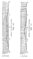
- the Patternator measures the GPM/square foot at radial distances from the centerline of the nozzle outlet. Results from the droplet diameter analysis and patternization tests for the control nozzle are presented in the Table and in Fig. 10, respectively.
- a liquid water/air mixture was introduced to the inventive nozzle (in this case the Maxipass nozzle with the horn structure removed therefrom) at a water flow rate and pressure of 245 gpm and 36 psi, respectively; and at an air flow rate and pressure of 790 scfm and 44.3 psi, respectively.
- the exiting atomized liquid was tested for atomization using the Speedview Analyzer.
- a liquid water/air mixture was introduced to the inventive nozzle at a water flow rate and pressure of 245 gpm and 36 psi, respectively; and at an air flow rate and pressure of 790 scfm and 44.3 psi, respectively.
- the exiting atomized liquid was tested for patternization using the Patternator for a duration of 3 seconds.
- the Sauter mean diameter using the inventive nozzle is around 58% lower than the Sauter mean diameter using the control nozzle and the vol. % of droplets having a diameter greater than 1000 microns using the inventive nozzle is around 79% lower than the vol. % of droplets having a diameter greater than 1000 microns using the control nozzle.
- This significant reduction in droplet size represents a major improvement in atomization efficiency.
- the patternization using the control nozzle was basically bimodal whereas the patternization using the inventive nozzle was unimodal, which is preferred, because unimodal distribution results in a more uniform distribution of droplets throughout the cone of the spray.
Abstract
Description
- The present invention relates to the atomization of a liquid stream. In another aspect, the invention relates to a method for atomizing and uniformly distributing an oil feed stream in a coker unit, or into a stream of fluidized catalyst in a fluidized catalytic cracking (FCC) unit.
- The process of atomizing a liquid stream for such purposes as rapid cooling of the liquid (artificial snow making) or enhanced contact of the atomized liquid with another medium, such as a fluidized catalyst, is well known in the art. It would clearly be desirable to provide an improved process for atomizing a liquid stream.
- A specific example of an atomization process is the atomization of an oil stream in an FCC unit prior to contacting the oil stream with a fluidized catalyst. Typical FCC unit operations are described below.
- Fluidized catalytic cracking of heavy petroleum fractions to produce products such as gasoline and heating oils is well known in the art. In fluidized catalytic cracking, heavy petroleum fractions are often preheated prior to contact with hot, fluidized catalyst particles in a riser reactor. The contact time in the riser reactor is generally in the order of a few seconds. The relatively short contact time encourages the production of gasoline and heating oil range hydrocarbons. Longer contact times can result in overcracking to undesirable end products, such as methane and coke. Important aspects of contacting the heavy petroleum fraction with the fluidized catalyst include the atomization of the heavy petroleum fraction and uniform distribution of the atomized heavy petroleum fraction within the fluidized catalyst. Non-uniform distribution of the heavy petroleum fraction in the fluidized catalyst can lead to localized regions of high catalyst-to-oil ratios and overcracking. Also, poor atomization of the heavy petroleum fraction can lead to localized regions of low catalyst-to-oil ratios resulting in wetting of the catalyst which results in increased coke laydown. In addition, if the heavy petroleum fraction is not sufficiently atomized and does not directly contact the fluidized catalyst upon injection into the riser reactor, then thermal cracking can occur instead of catalytic cracking. Thermal cracking can result in the generation of the undesirable end products of methane and coke. Excess coke is undesirable because the process duties of the stripper and regenerator are increased and the coke can be deposited on the surfaces of the equipment involved. It would be clearly desirable to provide a process in which an oil feed stream comprising a heavy petroleum fraction is sufficiently atomized and uniformly distributed within a fluidized catalyst in a fluidized catalytic cracking process.
- It is an object of the present invention to provide a method of atomizing a liquid stream in a manner that increases the atomization efficiency.
- It is yet another object of the present invention to improve the efficiency of FCC operations.
- It is still another object of the present invention to improve the efficiency of coker operations by improving the atomization and distribution of the oil feed stream prior to introduction into a coking reactor.
- Another object of the present invention is to provide a method for atomizing an oil feed stream for catalytic conversion.
- A yet further object of the present invention is to provide a method for atomizing and uniformly distributing an oil feed stream into a fluidized catalyst.
- In accordance with the present invention, a method for atomizing a liquid stream comprises introducing the liquid stream and introducing an atomizing enhancing medium to the inlet of a nozzle comprising a fluid conduit having an outlet orifice having a diameter and swirl-imparting means within the conduit for imparting a rotational component of motion to liquid flowing therethrough wherein the swirl-imparting means has an opening therethrough transversely of the fluid conduit which is substantially smaller than the outlet orifice and is in coaxial alignment therewith, the swirl-imparting means including sinusoidal portions in edge-to-edge relation spanning adjacent semi-circular segments of the fluid conduit, each sinusoidal portion including convex and concave lobes, the convex lobes being disposed toward the inlet end of the conduit and the concave lobes being offset axially from the convex lobes a distance approximately equal to the diameter of the outlet orifice, the convex and concave lobes being in alternate circumferential sequence in the fluid conduit. and withdrawing the liquid stream and the atomizing enhancing medium from the outlet orifice of the nozzle thereby at least partially atomizing the liquid stream to form an atomized liquid stream; wherein the atomized liquid stream does not contact a fluid deflecting device upon exit from the outlet orifice.
- Other objects and advantages of the invention will be apparent from the detailed description of the invention and the appended claims.
-
- FIG. 1 is an elevational view of a nozzle useful in relation to this invention.
- FIG. 2 is a top plan view of the nozzle of FIG. 1.
- FIG. 3 is a cross-sectional view taken along
line 3--3 of FIG. 2. - FIG. 4 is a bottom plane view as seen from
line 4--4 of FIG. 3. - FIG. 5 is a perspective view partly in section of the spray nozzle shown in FIG. 1.
- FIG. 6 schematically illustrates certain features of one type of FCC unit embodying certain features of the nozzle of the present invention.
- FIG. 7 is an enlarged cut-away view showing in greater detail certain features of the feed injection zone of the FCC unit shown in FIG. 6.
- FIG. 8 is an enlarged cross-sectional view taken along line 8 - 8 of FIG. 7 showing in greater detail certain features of the feed injection zone shown in FIG.'s 6 and 7.
- FIG. 9 is an elevational view showing the nozzle of FIG. 1 having attached thereto a horn typically used with such nozzle by those skilled in the FCC art.
- FIG. 10 is a plot of radial distance vs. GPM/Ft.2 showing the distribution of a water spray upon exit from the nozzle of FIG. 9.
- FIG. 11 is a plot of radial distance vs. GPM/Ft.2 showing the distribution of a water spray upon exit from the nozzle of FIG.'s 1 - 5.
-
- The apparatus and process of the present invention will be described with reference to the drawings. Reference to the specific configurations of the drawings is not meant to limit the invention to the details of the drawings disclosed in conjunction therewith.
- The nozzle useful in the present invention comprises, consists of, or consists essentially of a fluid conduit having an outlet orifice and swirl-imparting means within the fluid conduit. The swirl-imparting means can impart a rotational component of motion to liquid flowing therethrough. More particularly, the nozzle does not have a horn or other fluid deflecting device at the outlet of the outlet orifice.
- In a preferred embodiment, and referring in detail to FIG.'s 1 - 5, the nozzle 6 can be a tubular unitary body of any desirable external configuration. As shown, the nozzle is preferably externally threaded at its
inlet end 8 and a polygonal drive flange 9 can be provided for engagement by a wrench when it is desired to tighten the nozzle in a threaded fitting. The outlet end of the nozzle has an outlet orifice 10 of cylindrical configuration which extends through theouter end wall 11 of the nozzle and intersects with frustoconical surface 12 (FIG. 3), which constitutes the upper wall of a mixing oroutlet chamber 14. Theoutlet chamber 14 is also defined by the inner diameter orcylindrical bore 16 of the nozzle. - Swirl-imparting means can be provided by transversely extending
vanes mixing chamber 14 frominlet chamber 22 whoseinner wall 24 is a continuation ofbore 16. - A liquid stream is introduced to the inlet end of nozzle 6. An atomizing enhancing medium is also introduced to the inlet end of nozzle 6.
- The liquid stream and atomizing enhancing medium are preferably introduced to the nozzle as a turbulent mixture. The liquid stream is preferably an oil stream and the atomizing enhancing medium is preferably steam.
- The liquid stream and atomizing enhancing medium mixture passes through the swirl-imparting means in
bore 16, comprising, consisting of, or consisting essentially ofvanes - A central opening 28 (Fig 4.) defined by the
vanes -
Vanes vanes vane central opening 28 is defined. - Viewed in the direction of fluid flow (FIG. 4),
vane 18 has aconvex lobe 30, in one quadrant of the passage facing upstream and aconcave lobe 32 in the adjacent quadrant. Similarly,vane 20 has aconvex lobe 34 in a quadrant of the passage diametrically oppositeconvex lobe 30 of thevane 18 and aconcave lobe 36 in a quadrant diametrically oppositeconcave lobe 32 of thevane 18. The vanes18 and 20 are thus each approximately sinusoidal. - It will be noted that the two
vanes bore 16 and thus provide an unobstructed opening facing transversely of the nozzle bore of diameter designated by the reference character a (FIG. 5) sufficient to permit free passage therethrough of a sphere or ball having a diameter approximately equal to the diameter a . The dimension a , known as the "free passage diameter" lies in a radially extending plane of the nozzle and is approximately equal to the diameter of the outlet orifice 10. It is important, moreover, that the cross sectional area of thebore 16 be approximately 5-6 times the area of the orifice 10. Furthermore, the free passage diameter a should preferably be in the range of from about 40 to about 60 percent of the diameter of thebore 16. - The liquid stream and atomizing enhancing medium are withdrawn from nozzle 6 through outlet orifice 10 thereby at least partially atomizing the liquid stream to form an atomized liquid stream. The atomized liquid stream is then uniformly distributed into a medium such as, but not limited to, air or a fluidized catalyst.
- FIG. 6 shows one type of
FCC unit 200 which comprises afeed injection zone 201 having incorporated therein the nozzle 6 of FIG. 1.Feed injection zone 201 is connected in fluid flow communication with anoil feed line 202, an atomizing enhancingmedium line 203 and ariser reactor 204. Aconduit 205 connectsriser reactor 204, in fluid flow communication, with a catalyst/product separation zone 206 which typically contains at least one and preferably a plurality ofcyclone separators 208 and is connected in fluid flow communication with aconduit 210 for withdrawal of an overhead product from catalyst/product separation zone 206. Catalyst/product separation zone 206 is connected in fluid flow communication with a strippingsection 212 in which gas, preferably steam, is introduced fromlines section 212, in fluid flow communication, with a regeneration zone 220. Regeneration zone 220 is connected in fluid flow communication with aconduit 222 for introducing air to regeneration zone 220. Manipulative valve 224 (preferably a slide valve) connects regeneration zone 220, in fluid flow communication, with acatalyst conveyance zone 226.Catalyst conveyance zone 226 is connected in fluid flow communication with thefeed injection zone 201.Catalyst conveyance zone 226 is also connected in fluid flow communication with aconduit 228 for introducing fluidizing gas intocatalyst conveyance zone 226. - Referring to FIG.'s 7 and 8, therein is illustrated, in greater detail, feed
injection zone 201 from FIG. 6 including afrustroconical section 230, atypical guide 232 and the nozzle 6. - The
frustoconical section 230 is situated in an inverted manner and has acenterline axis 234. That is, the frustom end is situated below the base end, and the frustom and base ends are open to flow through thefrustoconical section 230. - In one embodiment, FIG. 8 is a downwardly looking sectional view of
feed injection zone 200 which illustrates the configuration of a plurality ofguides 232 aboutfrustoconical section 230 in which the nozzles 6 (not depicted in FIG. 8) are positioned. Referring again to FIG. 7, nozzle 6 is fixedly secured to guide 232 and is in fluid flow communication withfrustoconical section 230 of thefeed injection zone 201. Nozzle 6 can be fixedly secured to guide 232 by any means sufficient to provide a suitable seal. Preferably, nozzle 6 is either welded, bolted or threaded to guide 232. - Regarding the operation of the
FCC unit 20, and referring again to FIG. 6, an oil stream and an atomizing enhancing medium are introduced to feedinjection zone 201 throughlines riser reactor 204. As the oil stream is cracked the catalyst is progressively deactivated by the accumulation of hydrocarbons and coke on the surface and in the interstitial spaces of the catalyst. This partially deactivated catalyst is thereafter referred to as spent catalyst and passes fromriser reactor 204 to catalyst/product separation zone 206 viaconduit 205. Hydrocarbon product gases and spent catalyst separate in catalyst/product separation zone 206 and the hydrocarbon product gases exit throughconduit 210 with the spent catalyst flowing downwardly. The spent catalyst passes down through strippingsection 212 and is stripped of its hydrocarbons by counter flowing stripping gas fromconduits conduit 222. The regenerated catalyst then flows to thecatalyst conveyance zone 226 wherein fluidizing gas fromconduit 228, preferably steam, fluidizes the regenerated catalyst and aids in passing the regenerated catalyst to thefeed injection zone 201. - Referring again to FIG. 7, the oil stream and atomizing enhancing medium are introduced to the inlet of the nozzle 6 and exit from nozzle 6 as an atomized oil stream, as described above.
- The atomized oil stream is then uniformly distributed by nozzle 6 into the regenerated fluidized catalyst from catalyst conveyance zone 226 (FIG. 6) which is flowing through the frustoconical section 230 (FIG. 7) of the
feed injection zone 201. - Nozzles were tested for their effectiveness in atomization and patternization (distribution) of a liquid in two-phase (liquid/gas) flow.
- Presently, when a Maxipass nozzle for FCC service from BETE is supplied, a horn or bell is attached to the nozzle outlet which is thought by the supplier to improve patternization. Such horn or bell is shown in Fig. 9.
- A liquid water/air mixture was introduced to the control nozzle (as shown in FIG. 9) at a water flow rate and pressure of 245 gpm and 36 psi, respectively; and at an air flow rate and pressure of 790 scfm (standard cubic feet per minute) and 44.3 psi, respectively. The exiting atomized liquid was tested for atomization using a Speedview 760 Analysis system manufactured by Greenfield Instruments ("Speedview Analyzer"). The Speedview Analyzer measures droplet diameters and plots them into size distribution plots from which a Sauter mean diameter is calculated. The Sauter mean diameter is the diameter of a drop which has the same surface to volume ratio as the total drop population. Higher surface to volume ratios are desirable so as to maximize contact of the atomized liquid with the medium into which it is atomized (such as, for example, the fluidized catalyst in an FCC unit). Surface area to volume is inversely proportional to the diameter of the droplets. Thus, smaller diameter droplets have a higher surface area to volume ratio as compared to larger diameter droplets. Therefore, a smaller Sauter mean diameter is desirable.
- In a separate experiment, a liquid water/air mixture was introduced to the control nozzle at a water flow rate and pressure of 245 gpm and 35.7 psi, respectively; and at an air flow rate and pressure of 790 scfm and 43.8 psi, respectively. The exiting atomized liquid was tested for patternization using a Shop Patternator 770 device ("Patternator") for a duration of 2 seconds. The Patternator measures the GPM/square foot at radial distances from the centerline of the nozzle outlet. Results from the droplet diameter analysis and patternization tests for the control nozzle are presented in the Table and in Fig. 10, respectively.
- A liquid water/air mixture was introduced to the inventive nozzle (in this case the Maxipass nozzle with the horn structure removed therefrom) at a water flow rate and pressure of 245 gpm and 36 psi, respectively; and at an air flow rate and pressure of 790 scfm and 44.3 psi, respectively. The exiting atomized liquid was tested for atomization using the Speedview Analyzer.
- A liquid water/air mixture was introduced to the inventive nozzle at a water flow rate and pressure of 245 gpm and 36 psi, respectively; and at an air flow rate and pressure of 790 scfm and 44.3 psi, respectively. The exiting atomized liquid was tested for patternization using the Patternator for a duration of 3 seconds.
- Results from the droplet diameter analysis and patternization tests for the inventive nozzle are presented in the Table and in FIG. 11, respectively.
Control Nozzle Inventive Nozzle Arithmetic mean diameter, microns 210.2 178.8 Surface mean diameter, microns 294.6 213.1 Volume mean diameter, microns 427.8 257.6 Sauter mean diameter, microns 918.6 382.8 Vol. % of droplets with diameter greater than 1000 microns 65.9 14.0 - As can be seen from the data in the Table, the Sauter mean diameter using the inventive nozzle is around 58% lower than the Sauter mean diameter using the control nozzle and the vol. % of droplets having a diameter greater than 1000 microns using the inventive nozzle is around 79% lower than the vol. % of droplets having a diameter greater than 1000 microns using the control nozzle. This significant reduction in droplet size represents a major improvement in atomization efficiency.
- Also, as shown in Fig.'s 10 and 11, the patternization using the control nozzle was basically bimodal whereas the patternization using the inventive nozzle was unimodal, which is preferred, because unimodal distribution results in a more uniform distribution of droplets throughout the cone of the spray.
- Whereas this invention has been described in terms of the preferred embodiments, reasonable variations and modifications are possible by those skilled in the art. Such modifications are within the scope of the described invention and appended claims.
Claims (10)
- A method for atomizing a liquid stream comprising introducing said liquid stream and introducing an atomizing enhancing medium to the inlet of a nozzle comprising a fluid conduit having an outlet orifice having a diameter and swirl-imparting means within said conduit for imparting a rotational component of motion to liquid flowing therethrough; wherein said swirl-imparting means has an opening therethrough transversely of said fluid conduit which is substantially smaller than said outlet orifice and is in coaxial alignment therewith, said swirl-imparting means including sinusoidal portions in edge-to-edge relation spanning adjacent semi-circular segments of said fluid conduit, each sinusoidal portion including convex and concave lobes, said convex lobes being disposed toward the inlet end of said conduit and said concave lobes being offset axially from said convex lobes a distance approximately equal to the diameter of said outlet orifice, said convex and concave lobes being in alternate circumferential sequence in said fluid conduit; and
withdrawing said liquid stream and said atomizing enhancing medium from said outlet orifice of said nozzle thereby at least partially atomizing said liquid stream to form an atomized liquid stream; wherein said atomized liquid stream does not contact a fluid deflecting device upon exit from said outlet orifice. - The method of claim 1, wherein a spherical ball having a diameter approximately equal to the diameter of said outlet orifice is capable of passing between the axially offset lobes of said swirl-imparting means, in particular wherein the diameter of said spherical ball is in the range of from 40 to 60 percent of the diameter of said fluid conduit.
- The method of claim 1, wherein said sinusoidal portions have circumferentially overlapping inner edge portions and wherein each of said inner edge portions has an arcuate recess to form an opening through said sinusoidal portions, in particular wherein said opening through said sinusoidal portions has a cross sectional area that is 5 to 20 percent of the cross sectional area of said outlet orifice; and wherein said opening is in axial alignment with said outlet orifice.
- The method of claim 1, wherein the cross sectional area of said fluid conduit is 5 to 6 times the cross sectional area of said outlet orifice.
- The method of claim 1, wherein said liquid stream and said atomizing enhancing medium are introduced to said nozzle as a turbulent mixture.
- The method of claim 5, wherein said turbulent mixture passes through said swirl-imparting means creating an annular-mist flow mixture, in particular wherein said annular-mist flow mixture is withdrawn from said nozzle thereby at least partially atomizing said liquid stream to form said atomized liquid stream, or wherein said annular-mist flow mixture is substantially circumferentially uniform within said nozzle.
- The method of claim 1, wherein said atomizing enhancing medium is steam.
- The method of claim 1, wherein said liquid stream is an oil stream.
- The method of claim 1, wherein said atomized liquid stream is uniformly distributed into a fluidized catalyst upon exit from said nozzle.
- The method of claim 1, wherein said atomized liquid stream is uniformly distributed into a fluidized catalyst upon exit from said nozzle within a fluidized catalytic cracking unit.
Applications Claiming Priority (2)
| Application Number | Priority Date | Filing Date | Title |
|---|---|---|---|
| US131377 | 2002-04-24 | ||
| US10/131,377 US20030201334A1 (en) | 2002-04-24 | 2002-04-24 | Liquid feed atomization |
Publications (2)
| Publication Number | Publication Date |
|---|---|
| EP1357164A2 true EP1357164A2 (en) | 2003-10-29 |
| EP1357164A3 EP1357164A3 (en) | 2003-11-26 |
Family
ID=28790981
Family Applications (1)
| Application Number | Title | Priority Date | Filing Date |
|---|---|---|---|
| EP03008823A Withdrawn EP1357164A3 (en) | 2002-04-24 | 2003-04-24 | Liquid feed atomization |
Country Status (2)
| Country | Link |
|---|---|
| US (1) | US20030201334A1 (en) |
| EP (1) | EP1357164A3 (en) |
Families Citing this family (5)
| Publication number | Priority date | Publication date | Assignee | Title |
|---|---|---|---|---|
| US7670478B2 (en) * | 2004-12-30 | 2010-03-02 | Exxonmobil Research And Engineering Company | FCC feed injection system |
| US7758817B2 (en) * | 2006-08-09 | 2010-07-20 | Uop Llc | Device for contacting high contaminated feedstocks with catalyst in an FCC unit |
| GB0810299D0 (en) * | 2008-06-06 | 2008-07-09 | Rolls Royce Plc | An apparatus and method for evaluating a hydrocarbon to determine the propensity for coke formation |
| CN113462428B (en) * | 2021-07-07 | 2022-11-25 | 中国石油大学(华东) | Method for preparing chemicals through catalytic conversion of crude oil in double-pipe parallel multi-zone mode |
| CN113481027B (en) * | 2021-07-07 | 2022-11-25 | 中国石油大学(华东) | Method for preparing chemicals through double-tube series multi-zone catalytic conversion of crude oil |
Citations (5)
| Publication number | Priority date | Publication date | Assignee | Title |
|---|---|---|---|---|
| US3152065A (en) * | 1961-09-14 | 1964-10-06 | Exxon Research Engineering Co | Feed injector for cracking of petroleum |
| US3654140A (en) * | 1970-08-12 | 1972-04-04 | Exxon Research Engineering Co | Novel cat cracking oil feed injector design |
| FR2587034A1 (en) * | 1985-08-09 | 1987-03-13 | Total Engineering Research Cy | Process and device for cracking residual oils |
| US4948568A (en) * | 1983-02-04 | 1990-08-14 | Chevron Research Company | Method and apparatus for liquid feed dispersion in fluid catalytic cracking systems |
| US5232165A (en) * | 1989-11-27 | 1993-08-03 | Pierre Tournier | Sprinkling device for showers |
Family Cites Families (15)
| Publication number | Priority date | Publication date | Assignee | Title |
|---|---|---|---|---|
| US1310687A (en) * | 1919-07-22 | Spray-nozzle | ||
| US4014470A (en) * | 1976-03-01 | 1977-03-29 | Bete Fog Nozzle, Inc. | Conical spray nozzle |
| US4601814A (en) * | 1983-05-27 | 1986-07-22 | Total Engineering And Research Company | Method and apparatus for cracking residual oils |
| US4875996A (en) * | 1986-02-28 | 1989-10-24 | Chevron Research Company | Method for liquid feed dispersion in fluid catalytic cracking systems |
| US5061457A (en) * | 1988-02-03 | 1991-10-29 | Chevron Research & Technology Company | Apparatus for liquid feed dispersion in fluid catalytic cracking systems |
| US5298155A (en) * | 1990-02-27 | 1994-03-29 | Exxon Research & Engineering Co. | Controlling yields and selectivity in a fluid catalytic cracker unit |
| US5242577A (en) * | 1991-07-12 | 1993-09-07 | Mobil Oil Corporation | Radial flow liquid sprayer for large size vapor flow lines and use thereof |
| US5289976A (en) * | 1991-12-13 | 1994-03-01 | Mobil Oil Corporation | Heavy hydrocarbon feed atomization |
| US5306418A (en) * | 1991-12-13 | 1994-04-26 | Mobil Oil Corporation | Heavy hydrocarbon feed atomization |
| US5553783A (en) * | 1995-01-09 | 1996-09-10 | Bete Fog Nozzle, Inc. | Flat fan spray nozzle |
| US5794857A (en) * | 1995-03-07 | 1998-08-18 | Shell Oil Company | Feed nozzle |
| US5692682A (en) * | 1995-09-08 | 1997-12-02 | Bete Fog Nozzle, Inc. | Flat fan spray nozzle |
| US5948241A (en) * | 1997-08-05 | 1999-09-07 | Owen; Hartley | Orifice plate feed nozzle and atomization process |
| US6076744A (en) * | 1998-12-23 | 2000-06-20 | Spraying Systems Co. | Full cone spray nozzle |
| US6179997B1 (en) * | 1999-07-21 | 2001-01-30 | Phillips Petroleum Company | Atomizer system containing a perforated pipe sparger |
-
2002
- 2002-04-24 US US10/131,377 patent/US20030201334A1/en not_active Abandoned
-
2003
- 2003-04-24 EP EP03008823A patent/EP1357164A3/en not_active Withdrawn
Patent Citations (5)
| Publication number | Priority date | Publication date | Assignee | Title |
|---|---|---|---|---|
| US3152065A (en) * | 1961-09-14 | 1964-10-06 | Exxon Research Engineering Co | Feed injector for cracking of petroleum |
| US3654140A (en) * | 1970-08-12 | 1972-04-04 | Exxon Research Engineering Co | Novel cat cracking oil feed injector design |
| US4948568A (en) * | 1983-02-04 | 1990-08-14 | Chevron Research Company | Method and apparatus for liquid feed dispersion in fluid catalytic cracking systems |
| FR2587034A1 (en) * | 1985-08-09 | 1987-03-13 | Total Engineering Research Cy | Process and device for cracking residual oils |
| US5232165A (en) * | 1989-11-27 | 1993-08-03 | Pierre Tournier | Sprinkling device for showers |
Also Published As
| Publication number | Publication date |
|---|---|
| EP1357164A3 (en) | 2003-11-26 |
| US20030201334A1 (en) | 2003-10-30 |
Similar Documents
| Publication | Publication Date | Title |
|---|---|---|
| US4555328A (en) | Method and apparatus for injecting liquid hydrocarbon feed and steam into a catalytic cracking zone | |
| CA2040030C (en) | Fcc feed injector | |
| AU758217B2 (en) | Feed injection system for catalytic cracking process | |
| US5139748A (en) | FCC riser with transverse feed injection | |
| AU753170B2 (en) | Atomizing feed nozzle and method of use thereof | |
| TWI401118B (en) | Fcc feed injection system | |
| ZA200603658B (en) | Feed Nozzle Assembly | |
| CA2372425A1 (en) | Atomizer system | |
| US6503461B1 (en) | Feed injector with internal connections | |
| EP0933135B1 (en) | Atomizing nozzle and method of use thereof | |
| US11285451B2 (en) | Injection device, in particular for injecting a hydrocarbon feedstock into a refining unit | |
| EP1357164A2 (en) | Liquid feed atomization | |
| AU2005323169B2 (en) | FCC feed injection for atomizing feed | |
| US4948568A (en) | Method and apparatus for liquid feed dispersion in fluid catalytic cracking systems | |
| US4640463A (en) | Apparatus for injecting liquid hydrocarbon feed and steam into a catalytic cracking zone | |
| US4675099A (en) | Flowing catalyst particles in annular stream around a plug in lift pot | |
| CA2367369A1 (en) | Process and apparatus for atomizing fcc feed oil | |
| CN110961044A (en) | Nozzle for lifting pipe of catalytic cracking unit and application thereof | |
| JP2004500443A (en) | FCC process incorporating atomizing FCC feedstock |
Legal Events
| Date | Code | Title | Description |
|---|---|---|---|
| PUAI | Public reference made under article 153(3) epc to a published international application that has entered the european phase |
Free format text: ORIGINAL CODE: 0009012 |
|
| PUAL | Search report despatched |
Free format text: ORIGINAL CODE: 0009013 |
|
| 17P | Request for examination filed |
Effective date: 20030424 |
|
| AK | Designated contracting states |
Kind code of ref document: A2 Designated state(s): AT BE BG CH CY CZ DE DK EE ES FI FR GB GR HU IE IT LI LU MC NL PT RO SE SI SK TR |
|
| AX | Request for extension of the european patent |
Extension state: AL LT LV MK |
|
| AK | Designated contracting states |
Kind code of ref document: A3 Designated state(s): AT BE BG CH CY CZ DE DK EE ES FI FR GB GR HU IE IT LI LU MC NL PT RO SE SI SK TR |
|
| AX | Request for extension of the european patent |
Extension state: AL LT LV MK |
|
| RIC1 | Information provided on ipc code assigned before grant |
Ipc: 7F 23D 11/38 B Ipc: 7F 23D 11/10 B Ipc: 7B 05B 1/34 B Ipc: 7C 10G 11/18 A |
|
| AKX | Designation fees paid |
Designated state(s): AT BE BG CH CY CZ DE DK EE ES FI FR GB GR HU IE IT LI LU MC NL PT RO SE SI SK TR |
|
| 17Q | First examination report despatched |
Effective date: 20041230 |
|
| GRAP | Despatch of communication of intention to grant a patent |
Free format text: ORIGINAL CODE: EPIDOSNIGR1 |
|
| STAA | Information on the status of an ep patent application or granted ep patent |
Free format text: STATUS: THE APPLICATION IS DEEMED TO BE WITHDRAWN |
|
| 18D | Application deemed to be withdrawn |
Effective date: 20070411 |