EP1357056B1 - Eckenprofil für den Stoss- und Lastschutz an den Ecken von verpackten Gegenständen - Google Patents
Eckenprofil für den Stoss- und Lastschutz an den Ecken von verpackten Gegenständen Download PDFInfo
- Publication number
- EP1357056B1 EP1357056B1 EP02009468A EP02009468A EP1357056B1 EP 1357056 B1 EP1357056 B1 EP 1357056B1 EP 02009468 A EP02009468 A EP 02009468A EP 02009468 A EP02009468 A EP 02009468A EP 1357056 B1 EP1357056 B1 EP 1357056B1
- Authority
- EP
- European Patent Office
- Prior art keywords
- pyramid
- corner
- edges
- corner profile
- foamed material
- Prior art date
- Legal status (The legal status is an assumption and is not a legal conclusion. Google has not performed a legal analysis and makes no representation as to the accuracy of the status listed.)
- Expired - Lifetime
Links
- 230000035939 shock Effects 0.000 title description 5
- 230000001012 protector Effects 0.000 title description 2
- 239000000463 material Substances 0.000 claims abstract description 17
- 230000001681 protective effect Effects 0.000 claims description 26
- -1 polyethylene Polymers 0.000 claims description 4
- 239000000853 adhesive Substances 0.000 claims description 3
- 239000004033 plastic Substances 0.000 claims description 3
- 229920003023 plastic Polymers 0.000 claims description 3
- 239000004698 Polyethylene Substances 0.000 claims description 2
- 239000004743 Polypropylene Substances 0.000 claims description 2
- 239000004793 Polystyrene Substances 0.000 claims description 2
- 230000001070 adhesive effect Effects 0.000 claims description 2
- 229920000573 polyethylene Polymers 0.000 claims description 2
- 229920001155 polypropylene Polymers 0.000 claims description 2
- 229920002223 polystyrene Polymers 0.000 claims description 2
- 229920002725 thermoplastic elastomer Polymers 0.000 claims description 2
- 230000000717 retained effect Effects 0.000 claims 1
- 238000009826 distribution Methods 0.000 abstract description 21
- 239000006260 foam Substances 0.000 abstract description 18
- 239000006261 foam material Substances 0.000 abstract 2
- 230000000694 effects Effects 0.000 description 3
- 238000005520 cutting process Methods 0.000 description 2
- 238000013016 damping Methods 0.000 description 2
- 238000001746 injection moulding Methods 0.000 description 2
- 239000010410 layer Substances 0.000 description 2
- 238000004519 manufacturing process Methods 0.000 description 2
- 239000002184 metal Substances 0.000 description 2
- 239000002984 plastic foam Substances 0.000 description 2
- 239000012790 adhesive layer Substances 0.000 description 1
- 230000006735 deficit Effects 0.000 description 1
- 238000004049 embossing Methods 0.000 description 1
- 238000003754 machining Methods 0.000 description 1
- 230000004048 modification Effects 0.000 description 1
- 238000012986 modification Methods 0.000 description 1
- 230000009993 protective function Effects 0.000 description 1
- 238000005507 spraying Methods 0.000 description 1
- 238000003860 storage Methods 0.000 description 1
Images



Classifications
-
- B—PERFORMING OPERATIONS; TRANSPORTING
- B65—CONVEYING; PACKING; STORING; HANDLING THIN OR FILAMENTARY MATERIAL
- B65D—CONTAINERS FOR STORAGE OR TRANSPORT OF ARTICLES OR MATERIALS, e.g. BAGS, BARRELS, BOTTLES, BOXES, CANS, CARTONS, CRATES, DRUMS, JARS, TANKS, HOPPERS, FORWARDING CONTAINERS; ACCESSORIES, CLOSURES, OR FITTINGS THEREFOR; PACKAGING ELEMENTS; PACKAGES
- B65D81/00—Containers, packaging elements, or packages, for contents presenting particular transport or storage problems, or adapted to be used for non-packaging purposes after removal of contents
- B65D81/02—Containers, packaging elements, or packages, for contents presenting particular transport or storage problems, or adapted to be used for non-packaging purposes after removal of contents specially adapted to protect contents from mechanical damage
- B65D81/05—Containers, packaging elements, or packages, for contents presenting particular transport or storage problems, or adapted to be used for non-packaging purposes after removal of contents specially adapted to protect contents from mechanical damage maintaining contents at spaced relation from package walls, or from other contents
- B65D81/053—Corner, edge or end protectors
- B65D81/055—Protectors contacting three surfaces of the packaged article, e.g. three-sided edge protectors
- B65D81/056—Protectors contacting three surfaces of the packaged article, e.g. three-sided edge protectors the surfaces being generally perpendicular to each other, e.g. three-sided corner protectors
-
- B—PERFORMING OPERATIONS; TRANSPORTING
- B65—CONVEYING; PACKING; STORING; HANDLING THIN OR FILAMENTARY MATERIAL
- B65D—CONTAINERS FOR STORAGE OR TRANSPORT OF ARTICLES OR MATERIALS, e.g. BAGS, BARRELS, BOTTLES, BOXES, CANS, CARTONS, CRATES, DRUMS, JARS, TANKS, HOPPERS, FORWARDING CONTAINERS; ACCESSORIES, CLOSURES, OR FITTINGS THEREFOR; PACKAGING ELEMENTS; PACKAGES
- B65D2581/00—Containers, packaging elements, or packages, for contents presenting particular transport or storage problems, or adapted to be used for non-packaging purposes after removal of contents
- B65D2581/02—Containers, packaging elements, or packages, for contents presenting particular transport or storage problems, or adapted to be used for non-packaging purposes after removal of contents specially adapted to protect contents from mechanical damage
- B65D2581/05—Containers, packaging elements, or packages, for contents presenting particular transport or storage problems, or adapted to be used for non-packaging purposes after removal of contents specially adapted to protect contents from mechanical damage maintaining contents at spaced relation from package walls, or from other contents
- B65D2581/051—Details of packaging elements for maintaining contents at spaced relation from package walls, or from other contents
- B65D2581/052—Materials
- B65D2581/055—Plastic in general, e.g. foamed plastic, molded plastic, extruded plastic
Definitions
- Protective corners (DE 91 11 983.9 U1, DE 87 00 167.5 U1) are placed on the corners of articles to be packaged in order to compensate for shock and stacking effects during transport or storage of the packaged objects. Since the corner loads occurring in the stacking of the items can be very large, the wall thickness and the side surfaces of the protective corners must be very large, which means a large amount of material both in terms of production and disposal.
- Protective corners in the embodiment described above are cut out of a cylinder of foam so that the outer surface and the inner surface are connected by an extension surface which is part of the cylinder wall and terminates in three convexly curved end edges in the axis line and the outer edges of the Outside pyramid formed levels at a right angle to each other.
- a corner profile according to the preamble of claim 1 which comprises a pyramid-type load distribution element, on the inside of which a self-adhesive plastic foam layer is provided.
- the plastic foam layer is preferably applied by vacuum suction, as a self-adhesive layer or by spraying onto the inner surface of the load distribution element.
- the invention has for its object to provide a corner profile of the type described above, which can be used to compensate for high shock and pressure loads with reduced material costs for the corner protection foam and while ensuring adequate protection.
- this object is achieved in that on the outer surface of the protective corner, a load distribution element made of rigid material in the form of a three-sided pyramid is held with triangular side surfaces and three pyramid edges, each pyramid edge has a length which is between the length of the outer edge of the outer pyramid and the double wall thickness of the foam, and the load distribution member has inside at its pyramid edges projections for releasably retaining engagement with the outer edges of the foam of the outer pyramid.
- the square side surfaces of the protective corner protrude over the triangular side surfaces of the load-distributing element arranged on it and ensure that a corner of a packaged object with foam continues to extend.
- the foam of the protective corner is expediently made of foamed polyethylene, polystyrene, polypropylene, thermoplastic elastomers or combinations thereof.
- the corner profile according to the invention in the form of the combination of the protective corner with the load distribution element mounted thereon ensures a high shock protection and load capacity without changing the damping effect, since the non-elastic rigid load distribution element, the force is transmitted to a large surface area of the foam of the protective corner.
- the wall thickness of the protective corner can be reduced without a significant impairment of its protective function, which further reduces the use of foam.
- the load distribution member is detachable from the protective corner and reusable upon wear of the foam.
- the corner profile of Fig. 1 and Fig. 5 further has a on the outer surface 2 of the protective corner of foam form-fitting load distribution element 8 of a stiff thin material, which has the shape of a three-sided pyramid with triangular side surfaces and three pyramid edges 9, each pyramid edge. 9 has a length which is between the length of the outer edge 3 of the outer pyramid and the double wall thickness s of the foam.
- the load distribution element 8 is made of a load-bearing hard material, such as sheet metal or hard plastic.
- the corner profile has a high degree of external stability, with the load distribution element 8 distributed in terms of area by impact and load the protective corner of foam transfers, whereby its wall thickness s can be substantially reduced compared to a protective corner equal damping effect without load distribution element.
- At least one projection 12 is provided on each pyramid edge 9 of the load distribution element 8 inside.
- the projections 12 are directed inwardly from the load distribution element 8 and can be produced by injection molding or by machining the load distribution element 8, for example by cutting, sawing or embossing.
- the outer surface 2 and the inner surface 4 of the protective corner by an extension surface 5 are interconnected, which is bounded by parallel to the axis line 11 generatrices and having mutually perpendicular end edges 10.
- the side surfaces of the outer surface 2 and the inner surface 4 are formed substantially square, whereby in each case six respectively abutting end edges 10 are formed at right angles, of which two adjoining lie in one and the same plane.
- 3 is preferably cut from a foam prism having a cross-section in the shape of an equilateral hexagon so that the extension surface 5 is part of the prism outer wall.
- the protective corner shown in Fig. 3 and Fig. 4 is cut from the hexagonal prism by means of three angular cutting tools colliding at one point.
- the inner edges 7 of the inner pyramid and the outer edges 3 of the outer pyramid are aligned so that they substantially coincide with the corners of the prism.
- end edges 10 are cut so that in each case inwardly directed flats 13 are formed, which can be seen in Fig. 5 and one of which in Fig. 3 by the dash-dotted lines Line 13 is indicated. Thereby, a deformation of the protective corner can be avoided, which could result if the thin leaking end edges 10 are brought into engagement with the object to be protected.
Landscapes
- Engineering & Computer Science (AREA)
- Mechanical Engineering (AREA)
- Buffer Packaging (AREA)
- Packages (AREA)
Description
- Die Erfindung betrifft ein Eckenprofil gemäß dem Oberbegriff des Anspruchs 1 für den Stoß- und Lastschutz an den Ecken von verpackten Gegenständen.
- Schutzecken (DE 91 11 983.9 U1, DE 87 00 167.5 U1) werden auf die Ecken von zu verpackenden Gegenständern aufgesetzt, um Stoß- und Stapellasteinwirkungen beim Transport oder der Lagerung der verpackten Gegenstände zu kompensieren. Da die bei der Stapelung der Gegenstände auftretenden Eckenbelastungen sehr groß werden können, müssen die Wandstärke und die Seitenflächen der Schutzecken sehr groß dimensioniert werden, was einen großen Materialaufwand sowohl hinsichtlich Herstellung als auch Entsorgung bedeutet.
- Schutzecken in der eingangs beschriebenen Ausgestaltung werden aus einem Zylinder aus Schaumstoff so herausgeschnitten, dass die Außenfläche und die Innenfläche durch eine Fortsatzfläche verbunden sind, die Teil der Zylinderwand ist und in drei konvex gekrümmten Endkanten ausläuft, die in den von der Achslinie und den Außenkanten der Außenpyramide gebildeten Ebenen unter einem rechten Winkel aneinander stoßen.
- Aus der US 4 838 427 ist ein Eckenprofil gemäß dem Oberbegriff des Anspruchs 1 bekannt, das ein pyramidenartiges Lastverteilungselement aufweist, auf dessen Innenseite eine selbstklebende Plastikschaumschicht vorgesehen ist. Die Plastikschaumschicht wird vorzugsweise durch ein Vakuumansaugen, als selbstklebende Schicht oder durch Aufsprühen auf die innere Fläche des Lastverteilungselements aufgebracht.
- Der Erfindung liegt die Aufgabe zugrunde, ein Eckenprofil der eingangs beschriebenen Art zu schaffen, mit dem sich bei reduziertem Materialaufwand für die Schutzecke aus Schaumstoff und unter Gewährleistung einer ausreichenden Schutzfunktion hohe Stoß- und Druckbelastungen kompensieren lassen.
- Erfindungsgemäß wird diese Aufgabe dadurch gelöst, dass auf der Außenfläche der Schutzecke ein Lastverteilungselement aus steifem Material in Form einer dreiseitigen Pyramide mit dreieckigen Seitenflächen und drei Pyramidenkanten gehalten ist, wobei jede Pyramidenkante eine Länge hat, die zwischen der Länge der Außenkante der Außenpyramide und der doppelten Wandstärke des Schaumstoffs liegt, und das Lastverteilungselement innen an seinen Pyramidenkanten Vorsprünge für einen lösbaren Halteeingriff mit den Außenkanten des Schaumstoffs der Außenpyramide aufweist.
- Eine bevorzugte Ausführungsform der Erfindung sieht vor, dass das Lastverteilungselement aus einem dünnen Blech- oder Hartkunststoffmaterial besteht, wobei im letzteren Fall das Lastverteilungselement vorzugsweise durch Spritzgießen hergestellt wird. Ein solches Lastverteilungselement kann auch nach Verschleiß der Schutzecke weiter verwendet werden, beispielweise zum Schutz vom Ecken an Möbelstücken.
- Wenn die Außenfläche und die Innenfläche der Schutzecke durch eine Fortsatzfläche verbunden sind, die von zur Achsenlinie parallel verlaufenden Mantellinien begrenzt ist und die zueinander rechtwinklige Endkanten aufweist, ergeben sich dadurch Einsparungen im Bereich des Schaumstoffs, dass die Seitenflächen der Außenfläche und der Innenfläche im Wesentlichen quadratisch sind, wodurch jeweils sechs jeweils rechtwinklig aneinandersto-βende Endkanten gebildet werden, von denen jeweils zwei aneinandergrenzende in ein und derselben Ebene liegen. In dieser Ausgestaltung lässt sich die Schutzecke aus einem Schaumstoffprisma mit einem Querschnitt in Form eines gleichseitigen Sechsecks so ausschneiden, dass die Fortsatzfläche ein Teil der Prismaaußenwand ist, was gegenüber, der bekannten Herstellung aus einem Schaumstoffzylinder eine Materialeinsparung von 10% und mehr ergibt. Dabei stehen die quadratischen Seitenflächen der Schutzecke über die auf ihr angeordneten dreieckigen Seitenflächen des Lastverteilungselements vor und sorgen für eine weiter erstreckte Umfassung einer Ecke eines verpackten Gegenstandes mit Schaumstoff.
- Der Schaumstoff der Schutzecke besteht zweckmäßigerweise aus geschäumtem Polyethylen, Polystyrol, Polypropylen, thermoplastischen Elastomeren oder Kombinationen daraus.
- Die von der Innenfläche und der Fortsatzfläche der Schutzecke gebildeten Endkanten sind vorzugsweise nach innen abgeflacht.
- Das erfindungsgemäße Eckenprofil in Form der Kombination der Schutzecke mit dem darauf angebrachten Lastverteilungselement sorgt für eine hohe Stoßabsicherung und Lastaufnahmefähigkeit ohne Veränderung der Dämpfungswirkung, da durch das nicht elastische starre Lastverteilungselement die Krafteinwirkung auf einen großen Flächeanteil des Schaumstoffs der Schutzecke übertragen wird. Dadurch kann die Wandstärke der Schutzecke ohne eine nennenswerte Beeinträchtigung ihrer Schutzfunktion verringert werden, was den Schaumstoffeinsatz weiter reduziert. Ferner ist das Lastverteilungselement von der Schutzecke abnehmbar und bei Verschleiß des Schaumstoffs wiederverwendbar ausgebildet.
- Anhand von Zeichnungen werden Ausführungsbeispiele der Erfindung näher erläutert. Es zeigt:
- Fig. 1
- in einer Seitenansicht schematisch ein Eckenprofil bestehend aus Schutzecke und Lastverteilungselement,
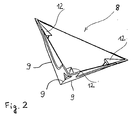
- Fig. 2
- eine axonometrische Darstellung des Lastverteilungselements,
- Fig. 3
- in einer Seitenansicht schematisch eine bevorzugte Ausführungsform eines Eckenprofils aus Schutzecke und Lastverteilungselement,
- Fig. 4
- in einer Ansicht von unten schematisch die Schutzecke von Fig. 3 und
- Fig. 5
- perspektivisch das Eckenprofil von Fig. 3.
- Fig. 1 zeigt ein Eckenprofil mit einer Schutzecke aus Schaumstoff, die eine Außenfläche 2 und Innenfläche 4 hat, die in einem einer vorgegebene Wandstärke s entsprechenden Abstand angeordnet und aus im Wesentlichen senkrecht zueinander angeordneten Seitenflächen unter Bildung einer Außenpyramide mit drei Außenkanten 3 und einer Innenpyramide mit drei Innenkanten 7 zusammensetzt sind. Die Spitzen 6 und 6' der Außenpyramide und der Innenpyramide liegen dabei auf einer Achsenlinie 11.
- Das Eckenprofil von Fig. 1 und Fig. 5 hat ferner ein auf der Außenfläche 2 der Schutzecke aus Schaumstoff formschlüssig angeordnetes Lastverteilungselement 8 aus einem steifen dünnen Material, das die Form einer dreiseitigen Pyramide mit dreieckigen Seitenflächen und drei Pyramidenkanten 9 hat, wobei jede Pyramidenkante 9 eine Länge hat, die zwischen der Länge der Außenkante 3 der Außenpyramide und der doppelten Wandstärke s des Schaumstoffs liegt.
- Das Lastverteilungselement 8 besteht aus einem tragfähigen harten Material, wie zum Beispiel Blech oder hartem Kunststoff. Dadurch hat das Eckenprofil eine hohe Außenstabilität, wobei das Lastverteilungselement 8 Stoß- und Lasteinwirkungen flächenmäßig verteilt auf die Schutzecke aus Schaumstoff überträgt, wodurch deren Wandstärke s verglichen mit einer Schutzecke gleicher Dämpfungswirkung ohne Lastverteilungselement wesentlich reduziert werden kann.
- Für einen lösbaren Hafteingriff mit der Außenkante 3 der Außenpyramide ist an jeder Pyramidenkante 9 des Lastverteilungselements 8 innen wenigstens ein Vorsprung 12 vorgesehen. Wie in Fig. 2 gezeigt ist, sind dabei die Vorsprünge 12 vom Lastverteilungselement 8 aus nach innen gerichtet und können durch Spritzgießen oder durch Bearbeitung des Lastverteilungselements 8, zum Beispiel durch Schneiden, Sägen oder Prägen, hergestellt werden.
- Wie in Fig. 3 gezeigt ist, sind die Außenfläche 2 und die Innenfläche 4 der Schutzecke durch eine Fortsatzfläche 5 miteinander verbunden, die von zur Achsenlinie 11 parallel verlaufenden Mantellinien begrenzt wird und die zueinander rechtwinklige Endkanten 10 aufweist. Die Seitenflächen der Außenfläche 2 und der Innenfläche 4 sind im Wesentlichen quadratisch ausgebildet, wodurch jeweils sechs jeweils rechtwinklig aneinanderstoßende Endkanten 10 gebildet werden, von denen jeweils zwei aneinandergrenzende in ein und derselben Ebene liegen. Die gezeigte Schutzecke von Fig. 3 wird vorzugsweise aus einem Schaumstoffprisma mit einem Querschnitt in Form eines gleichseitigen Sechsecks so ausgeschnitten, dass die Fortsatzfläche 5 ein Teil der Prismaaußenwand ist.
- Die in Fig.3 und Fig. 4 gezeigte Schutzecke wird aus dem Sechskantprisma mittels drei in einem Punkt zusammenstoßender eckiger Schneidwerkzeuge geschnitten. Die Innenkanten 7 der Innenpyramide und die Außenkanten 3 der Außenpyramide sind dabei so ausgerichtet, dass sie mit den Ecken des Prismas im Wesentlichen übereinstimmen.
- Bei einer Modifizierung der Schutzecke werden die von der Innenfläche 4 und der Fortsatzfläche 5 gebildeten Endkanten 10 so abgeschnitten, dass jeweils nach innen gerichtete Abflachungen 13 gebildet werden, die in Fig. 5 zu sehen sind und von denen eine in Fig. 3 durch die strichpunktierte Linie 13 angedeutet ist. Dadurch kann eine Verformung der Schutzecke vermieden werden, die sich ergeben könnte, wenn die dünn auslaufenden Endkanten 10 mit dem zu schützenden Gegenstand in Eingriff gebracht werden.
Claims (6)
- Eckenprofil für den Stoß- und Lastschutz an den Ecken von verpackten Gegenständen, welches eine Schutzecke aus Schaumstoff- mit einer Außenfläche (2) und einer Innenfläche (4) aufweist,- deren Abstand durch eine vorgegebene Wandstärke (s) festgelegt ist und- von denen sich jede aus drei zueinander im Wesentlichen senkrechten Seitenflächen unter Bildung einer Außenpyramide mit drei Außenkanten (3) und einer Innenpyramide mit drei Innenkanten (7) zusammensetzt, deren Spitzen (6, 6') auf einer Achsenlinie (11) liegen,- wobei auf der Außenfläche (2) ein Lastverteilungselement (8) aus dünnem steifem Material in Form einer dreiseitigen Pyramide mit dreieckigen Seitenflächen und drei Pyramidenkanten (9) gehalten ist,- wobei jede Pyramidenkante (9) eine Länge hat, die zwischen der Länge der Außenkante (3) der Außenpyramide und der doppelten Wandstärke (s) des Schaumstoffs liegt und, ,dadurch gekennzeichnet,- dass das Lastverteilungselement (8) innen an seinen Pyramidenkanten (9) Vorsprünge (12) für einen lösbaren Hafteingriff mit den Außenkanten (3) des Schaumstoffs der Außenpyramide hat.
- Eckenprofil nach Anspruch 1, dadurch gekennzeichnet, dass das Lastverteilungselement (8) aus einem dünnen Blech- oder Hartkunststoffmaterial besteht.
- Eckenprofil nach Anspruch 1 oder 2, wobei die Außenfläche (2) und die Innenfläche (4) der Schutzecke aus Schaumstoff durch eine Fortsatzfläche (5) verbunden sind, die von zur Achsenlinie (11) parallel verlaufenden Mantellinien begrenzt wird und die zueinander rechtwinklige Endkanten (10) aufweist,
dadurch gekennzeichnet,- dass die Seitenflächen der Außenfläche (2) und der Innenfläche (4) nicht dreieckig, sondern im Wesentlichen quadratisch sind,- wodurch jeweils sechs jeweils rechtwinklig aneinanderstoßende Endkanten (10) gebildet werden, von denen jeweils zwei aneinandergrenzende in ein und derselben Ebene liegen. - Eckenprofil nach Anspruch 3, dadurch gekennzeichnet, dass die Schutzecke aus einem Schaumstoffprisma mit einem Querschnitt in Form eines gleichseitigen Sechsecks so ausgeschnitten ist, dass die Fortsatzfläche (5) ein Teil der Prismaaußenwand ist.
- Eckenprofil nach Anspruch 3 oder 4, dadurch gekennzeichnet, dass die von der Innenfläche (4) und der Fortsatzfläche (5) gebildeten Endkanten (10) Abflachungen (13) aufweisen.
- Eckenprofil nach einem der vorhergehenden Ansprüche, dadurch gekennzeichnet, dass der Schaumstoff aus geschäumtem Polyethylen, Polystyrol, Polypropylen, thermoplastischen Elastomeren oder Kombinationen daraus besteht.
Priority Applications (3)
| Application Number | Priority Date | Filing Date | Title |
|---|---|---|---|
| EP02009468A EP1357056B1 (de) | 2002-04-25 | 2002-04-25 | Eckenprofil für den Stoss- und Lastschutz an den Ecken von verpackten Gegenständen |
| AT02009468T ATE316048T1 (de) | 2002-04-25 | 2002-04-25 | Eckenprofil für den stoss- und lastschutz an den ecken von verpackten gegenständen |
| DE50205620T DE50205620D1 (de) | 2002-04-25 | 2002-04-25 | Eckenprofil für den Stoss- und Lastschutz an den Ecken von verpackten Gegenständen |
Applications Claiming Priority (1)
| Application Number | Priority Date | Filing Date | Title |
|---|---|---|---|
| EP02009468A EP1357056B1 (de) | 2002-04-25 | 2002-04-25 | Eckenprofil für den Stoss- und Lastschutz an den Ecken von verpackten Gegenständen |
Publications (2)
| Publication Number | Publication Date |
|---|---|
| EP1357056A1 EP1357056A1 (de) | 2003-10-29 |
| EP1357056B1 true EP1357056B1 (de) | 2006-01-18 |
Family
ID=28685906
Family Applications (1)
| Application Number | Title | Priority Date | Filing Date |
|---|---|---|---|
| EP02009468A Expired - Lifetime EP1357056B1 (de) | 2002-04-25 | 2002-04-25 | Eckenprofil für den Stoss- und Lastschutz an den Ecken von verpackten Gegenständen |
Country Status (3)
| Country | Link |
|---|---|
| EP (1) | EP1357056B1 (de) |
| AT (1) | ATE316048T1 (de) |
| DE (1) | DE50205620D1 (de) |
Cited By (9)
| Publication number | Priority date | Publication date | Assignee | Title |
|---|---|---|---|---|
| USD602350S1 (en) | 2008-10-14 | 2009-10-20 | Lavelle Richard M | Corner protector |
| USD618995S1 (en) | 2009-08-06 | 2010-07-06 | Lavelle Richard M | Corner protector |
| USD624812S1 (en) | 2009-07-09 | 2010-10-05 | Lavelle Richard M | Corner protector |
| USD640919S1 (en) | 2010-05-13 | 2011-07-05 | Lavelle Richard M | Corner protector |
| USD647212S1 (en) | 2011-02-03 | 2011-10-18 | Lavelle Richard M | Surgical tray corner protector |
| USD660454S1 (en) | 2011-07-26 | 2012-05-22 | Lavelle Richard M | Surgical tray corner protector |
| USD704045S1 (en) | 2012-02-20 | 2014-05-06 | Richard M. Lavelle | Corner protector |
| USD709360S1 (en) | 2012-07-12 | 2014-07-22 | Richard M. Lavelle | Corner protector |
| USD770269S1 (en) | 2014-07-15 | 2016-11-01 | Velmed, Inc. | Corner protector |
Families Citing this family (2)
| Publication number | Priority date | Publication date | Assignee | Title |
|---|---|---|---|---|
| US7244004B2 (en) * | 2003-06-24 | 2007-07-17 | Tenn-Tax Plastics, Inc. | Corner protector |
| US9579165B2 (en) | 2007-01-29 | 2017-02-28 | Richard M. Lavelle | Surgical tray corner protector |
Family Cites Families (6)
| Publication number | Priority date | Publication date | Assignee | Title |
|---|---|---|---|---|
| US3836043A (en) * | 1971-12-30 | 1974-09-17 | Itt | Transit/combination case shock mount arrangement |
| DE8700165U1 (de) | 1987-01-03 | 1987-02-19 | Birmelin Jun., Hermann, 7800 Freiburg | Halterung für kerzenförmige Leuchtkörper |
| US4838427A (en) * | 1988-07-26 | 1989-06-13 | Hurley Richard D | Shipping protector |
| DE9111983U1 (de) | 1991-09-26 | 1991-11-14 | Teldix Gmbh, 69123 Heidelberg | Wiederverwendbare Polsterecken für den Transportschutz- und für die Lagerung von stoßempfindlichen Geräten |
| US5899088A (en) * | 1998-05-14 | 1999-05-04 | Throwleigh Technologies, L.L.C. | Phase change system for temperature control |
| JP2000255623A (ja) * | 1999-03-08 | 2000-09-19 | Kawakami Sangyo Kk | 包装用のコーナーパッド、サイドパッドおよびそれらを使用した包装箱 |
-
2002
- 2002-04-25 DE DE50205620T patent/DE50205620D1/de not_active Expired - Fee Related
- 2002-04-25 EP EP02009468A patent/EP1357056B1/de not_active Expired - Lifetime
- 2002-04-25 AT AT02009468T patent/ATE316048T1/de not_active IP Right Cessation
Cited By (12)
| Publication number | Priority date | Publication date | Assignee | Title |
|---|---|---|---|---|
| USD602350S1 (en) | 2008-10-14 | 2009-10-20 | Lavelle Richard M | Corner protector |
| USD612718S1 (en) | 2008-10-14 | 2010-03-30 | Lavelle Richard M | Corner protector |
| USD624812S1 (en) | 2009-07-09 | 2010-10-05 | Lavelle Richard M | Corner protector |
| USD618995S1 (en) | 2009-08-06 | 2010-07-06 | Lavelle Richard M | Corner protector |
| USD624813S1 (en) | 2009-08-06 | 2010-10-05 | Lavelle Richard M | Corner protector |
| USD640919S1 (en) | 2010-05-13 | 2011-07-05 | Lavelle Richard M | Corner protector |
| USD654356S1 (en) | 2010-05-13 | 2012-02-21 | Lavelle Richard M | Corner protector |
| USD647212S1 (en) | 2011-02-03 | 2011-10-18 | Lavelle Richard M | Surgical tray corner protector |
| USD660454S1 (en) | 2011-07-26 | 2012-05-22 | Lavelle Richard M | Surgical tray corner protector |
| USD704045S1 (en) | 2012-02-20 | 2014-05-06 | Richard M. Lavelle | Corner protector |
| USD709360S1 (en) | 2012-07-12 | 2014-07-22 | Richard M. Lavelle | Corner protector |
| USD770269S1 (en) | 2014-07-15 | 2016-11-01 | Velmed, Inc. | Corner protector |
Also Published As
| Publication number | Publication date |
|---|---|
| EP1357056A1 (de) | 2003-10-29 |
| ATE316048T1 (de) | 2006-02-15 |
| DE50205620D1 (de) | 2006-04-06 |
Similar Documents
| Publication | Publication Date | Title |
|---|---|---|
| DE69628658T2 (de) | Wabenförmige bloch | |
| EP0824471B1 (de) | Vorrichtung zum abpolstern von körperecken | |
| CH626851A5 (de) | ||
| DE69513963T2 (de) | Wabenkörper für aufprallschutz-strukturen | |
| EP0976882A2 (de) | Fugendichtungskörper | |
| EP1357056A1 (de) | Eckenprofil für den Stoss- und Lastschutz an den Ecken von verpackten Gegenständen | |
| DE69303903T2 (de) | Kantenschutz sowie gegenstand versehen mit einem solchen kantenschutz | |
| DE3535069A1 (de) | Daempfungseinrichtung | |
| DE69821683T2 (de) | Teppiche mit ineinander greifenden modularen Elementen für Sportwettkämpfe wie Ringen Karate, Judo und ähnliche und Verfahren zu deren Herstellung | |
| WO1994012344A1 (de) | Mehrschichtiger wellpappekörper | |
| EP2103549B1 (de) | Kantenschutz für empfindliche Transportgüter | |
| DE29712684U1 (de) | Mehrlagige Verbundplatte | |
| EP1488885B1 (de) | Gliederbahn, insbesondere für Werkzeugmaschinen | |
| EP1700795A1 (de) | Schutzprofil für einen plattenförmigen Körper | |
| DE4137809C2 (de) | Polsterteil und Verfahren zu seiner Herstellung | |
| DE29900732U1 (de) | Profilpolster für den Rand- und Kantenschutz von stoßempfindlichem Verpackungsgut | |
| DE20017581U1 (de) | Matratze | |
| DE20206596U1 (de) | Schutzecke | |
| DE19625472A1 (de) | Netz, insbesondere Oberflächenschutznetz, Rutschhemmnetz, Abstandshalternetz oder dergleichen sowie Verfahren zur Herstellung desselben | |
| EP1382546A1 (de) | Profilkörper zum Schutz von Gegenständen | |
| EP2189392B1 (de) | Kantenschutzprofil | |
| DE10127106B4 (de) | Grundbahn eines Verpackungsmaterials aus Papier, Pappe oder Kartonage | |
| DE4405847C2 (de) | Faltleiste mit gerundeter Biegekante | |
| DE29807554U1 (de) | Gefache | |
| DE29804878U1 (de) | Furnier |
Legal Events
| Date | Code | Title | Description |
|---|---|---|---|
| PUAI | Public reference made under article 153(3) epc to a published international application that has entered the european phase |
Free format text: ORIGINAL CODE: 0009012 |
|
| AK | Designated contracting states |
Kind code of ref document: A1 Designated state(s): AT BE CH CY DE DK ES FI FR GB GR IE IT LI LU MC NL PT SE TR |
|
| AX | Request for extension of the european patent |
Extension state: AL LT LV MK RO SI |
|
| 17P | Request for examination filed |
Effective date: 20040405 |
|
| AKX | Designation fees paid |
Designated state(s): AT BE CH CY DE DK ES FI FR GB GR IE IT LI LU MC NL PT SE TR |
|
| GRAP | Despatch of communication of intention to grant a patent |
Free format text: ORIGINAL CODE: EPIDOSNIGR1 |
|
| GRAS | Grant fee paid |
Free format text: ORIGINAL CODE: EPIDOSNIGR3 |
|
| GRAA | (expected) grant |
Free format text: ORIGINAL CODE: 0009210 |
|
| AK | Designated contracting states |
Kind code of ref document: B1 Designated state(s): AT BE CH CY DE DK ES FI FR GB GR IE IT LI LU MC NL PT SE TR |
|
| PG25 | Lapsed in a contracting state [announced via postgrant information from national office to epo] |
Ref country code: IT Free format text: LAPSE BECAUSE OF FAILURE TO SUBMIT A TRANSLATION OF THE DESCRIPTION OR TO PAY THE FEE WITHIN THE PRESCRIBED TIME-LIMIT;WARNING: LAPSES OF ITALIAN PATENTS WITH EFFECTIVE DATE BEFORE 2007 MAY HAVE OCCURRED AT ANY TIME BEFORE 2007. THE CORRECT EFFECTIVE DATE MAY BE DIFFERENT FROM THE ONE RECORDED. Effective date: 20060118 Ref country code: NL Free format text: LAPSE BECAUSE OF FAILURE TO SUBMIT A TRANSLATION OF THE DESCRIPTION OR TO PAY THE FEE WITHIN THE PRESCRIBED TIME-LIMIT Effective date: 20060118 Ref country code: GB Free format text: LAPSE BECAUSE OF FAILURE TO SUBMIT A TRANSLATION OF THE DESCRIPTION OR TO PAY THE FEE WITHIN THE PRESCRIBED TIME-LIMIT Effective date: 20060118 Ref country code: IE Free format text: LAPSE BECAUSE OF FAILURE TO SUBMIT A TRANSLATION OF THE DESCRIPTION OR TO PAY THE FEE WITHIN THE PRESCRIBED TIME-LIMIT Effective date: 20060118 Ref country code: FI Free format text: LAPSE BECAUSE OF FAILURE TO SUBMIT A TRANSLATION OF THE DESCRIPTION OR TO PAY THE FEE WITHIN THE PRESCRIBED TIME-LIMIT Effective date: 20060118 |
|
| REG | Reference to a national code |
Ref country code: GB Ref legal event code: FG4D Free format text: NOT ENGLISH |
|
| REG | Reference to a national code |
Ref country code: CH Ref legal event code: EP |
|
| REG | Reference to a national code |
Ref country code: IE Ref legal event code: FG4D Free format text: LANGUAGE OF EP DOCUMENT: GERMAN |
|
| REF | Corresponds to: |
Ref document number: 50205620 Country of ref document: DE Date of ref document: 20060406 Kind code of ref document: P |
|
| PG25 | Lapsed in a contracting state [announced via postgrant information from national office to epo] |
Ref country code: DK Free format text: LAPSE BECAUSE OF FAILURE TO SUBMIT A TRANSLATION OF THE DESCRIPTION OR TO PAY THE FEE WITHIN THE PRESCRIBED TIME-LIMIT Effective date: 20060418 Ref country code: SE Free format text: LAPSE BECAUSE OF FAILURE TO SUBMIT A TRANSLATION OF THE DESCRIPTION OR TO PAY THE FEE WITHIN THE PRESCRIBED TIME-LIMIT Effective date: 20060418 |
|
| PG25 | Lapsed in a contracting state [announced via postgrant information from national office to epo] |
Ref country code: AT Free format text: LAPSE BECAUSE OF NON-PAYMENT OF DUE FEES Effective date: 20060425 |
|
| PG25 | Lapsed in a contracting state [announced via postgrant information from national office to epo] |
Ref country code: ES Free format text: LAPSE BECAUSE OF FAILURE TO SUBMIT A TRANSLATION OF THE DESCRIPTION OR TO PAY THE FEE WITHIN THE PRESCRIBED TIME-LIMIT Effective date: 20060429 |
|
| PG25 | Lapsed in a contracting state [announced via postgrant information from national office to epo] |
Ref country code: CH Free format text: LAPSE BECAUSE OF NON-PAYMENT OF DUE FEES Effective date: 20060430 Ref country code: BE Free format text: LAPSE BECAUSE OF NON-PAYMENT OF DUE FEES Effective date: 20060430 Ref country code: LI Free format text: LAPSE BECAUSE OF NON-PAYMENT OF DUE FEES Effective date: 20060430 Ref country code: MC Free format text: LAPSE BECAUSE OF NON-PAYMENT OF DUE FEES Effective date: 20060430 |
|
| PG25 | Lapsed in a contracting state [announced via postgrant information from national office to epo] |
Ref country code: PT Free format text: LAPSE BECAUSE OF FAILURE TO SUBMIT A TRANSLATION OF THE DESCRIPTION OR TO PAY THE FEE WITHIN THE PRESCRIBED TIME-LIMIT Effective date: 20060619 |
|
| NLV1 | Nl: lapsed or annulled due to failure to fulfill the requirements of art. 29p and 29m of the patents act | ||
| GBV | Gb: ep patent (uk) treated as always having been void in accordance with gb section 77(7)/1977 [no translation filed] |
Effective date: 20060118 |
|
| REG | Reference to a national code |
Ref country code: IE Ref legal event code: FD4D |
|
| PG25 | Lapsed in a contracting state [announced via postgrant information from national office to epo] |
Ref country code: DE Free format text: LAPSE BECAUSE OF NON-PAYMENT OF DUE FEES Effective date: 20061101 |
|
| PLBE | No opposition filed within time limit |
Free format text: ORIGINAL CODE: 0009261 |
|
| STAA | Information on the status of an ep patent application or granted ep patent |
Free format text: STATUS: NO OPPOSITION FILED WITHIN TIME LIMIT |
|
| REG | Reference to a national code |
Ref country code: CH Ref legal event code: PL |
|
| 26N | No opposition filed |
Effective date: 20061019 |
|
| EN | Fr: translation not filed | ||
| BERE | Be: lapsed |
Owner name: ARMACELL ENTERPRISE G.M.B.H. Effective date: 20060430 |
|
| PG25 | Lapsed in a contracting state [announced via postgrant information from national office to epo] |
Ref country code: GR Free format text: LAPSE BECAUSE OF FAILURE TO SUBMIT A TRANSLATION OF THE DESCRIPTION OR TO PAY THE FEE WITHIN THE PRESCRIBED TIME-LIMIT Effective date: 20060419 Ref country code: FR Free format text: LAPSE BECAUSE OF FAILURE TO SUBMIT A TRANSLATION OF THE DESCRIPTION OR TO PAY THE FEE WITHIN THE PRESCRIBED TIME-LIMIT Effective date: 20070309 |
|
| PG25 | Lapsed in a contracting state [announced via postgrant information from national office to epo] |
Ref country code: TR Free format text: LAPSE BECAUSE OF FAILURE TO SUBMIT A TRANSLATION OF THE DESCRIPTION OR TO PAY THE FEE WITHIN THE PRESCRIBED TIME-LIMIT Effective date: 20060118 Ref country code: LU Free format text: LAPSE BECAUSE OF NON-PAYMENT OF DUE FEES Effective date: 20060425 |
|
| PG25 | Lapsed in a contracting state [announced via postgrant information from national office to epo] |
Ref country code: FR Free format text: LAPSE BECAUSE OF FAILURE TO SUBMIT A TRANSLATION OF THE DESCRIPTION OR TO PAY THE FEE WITHIN THE PRESCRIBED TIME-LIMIT Effective date: 20060430 |
|
| PG25 | Lapsed in a contracting state [announced via postgrant information from national office to epo] |
Ref country code: CY Free format text: LAPSE BECAUSE OF FAILURE TO SUBMIT A TRANSLATION OF THE DESCRIPTION OR TO PAY THE FEE WITHIN THE PRESCRIBED TIME-LIMIT Effective date: 20060118 Ref country code: FR Free format text: LAPSE BECAUSE OF FAILURE TO SUBMIT A TRANSLATION OF THE DESCRIPTION OR TO PAY THE FEE WITHIN THE PRESCRIBED TIME-LIMIT Effective date: 20060118 |