EP1357005A2 - Vorrichtung zum seitlichen Führen eines Wischblatts - Google Patents
Vorrichtung zum seitlichen Führen eines Wischblatts Download PDFInfo
- Publication number
- EP1357005A2 EP1357005A2 EP03006456A EP03006456A EP1357005A2 EP 1357005 A2 EP1357005 A2 EP 1357005A2 EP 03006456 A EP03006456 A EP 03006456A EP 03006456 A EP03006456 A EP 03006456A EP 1357005 A2 EP1357005 A2 EP 1357005A2
- Authority
- EP
- European Patent Office
- Prior art keywords
- wiper
- leaf spring
- wiper blade
- wiper strip
- clip
- Prior art date
- Legal status (The legal status is an assumption and is not a legal conclusion. Google has not performed a legal analysis and makes no representation as to the accuracy of the status listed.)
- Granted
Links
- XEEYBQQBJWHFJM-UHFFFAOYSA-N Iron Chemical compound [Fe] XEEYBQQBJWHFJM-UHFFFAOYSA-N 0.000 claims description 7
- 229910052742 iron Inorganic materials 0.000 claims description 3
- 210000002105 tongue Anatomy 0.000 description 7
- 210000000078 claw Anatomy 0.000 description 3
- 238000004026 adhesive bonding Methods 0.000 description 2
- 239000002184 metal Substances 0.000 description 2
- 229910052751 metal Inorganic materials 0.000 description 2
- 238000000034 method Methods 0.000 description 2
- 238000005476 soldering Methods 0.000 description 2
- 238000003466 welding Methods 0.000 description 2
- 229910000639 Spring steel Inorganic materials 0.000 description 1
- 238000005452 bending Methods 0.000 description 1
- 230000000694 effects Effects 0.000 description 1
- 230000002349 favourable effect Effects 0.000 description 1
- 238000002347 injection Methods 0.000 description 1
- 239000007924 injection Substances 0.000 description 1
- 238000004519 manufacturing process Methods 0.000 description 1
- 239000000463 material Substances 0.000 description 1
- 238000004080 punching Methods 0.000 description 1
- 230000000007 visual effect Effects 0.000 description 1
Images
Classifications
-
- B—PERFORMING OPERATIONS; TRANSPORTING
- B60—VEHICLES IN GENERAL
- B60S—SERVICING, CLEANING, REPAIRING, SUPPORTING, LIFTING, OR MANOEUVRING OF VEHICLES, NOT OTHERWISE PROVIDED FOR
- B60S1/00—Cleaning of vehicles
- B60S1/02—Cleaning windscreens, windows or optical devices
- B60S1/04—Wipers or the like, e.g. scrapers
- B60S1/32—Wipers or the like, e.g. scrapers characterised by constructional features of wiper blade arms or blades
- B60S1/40—Connections between blades and arms
-
- B—PERFORMING OPERATIONS; TRANSPORTING
- B60—VEHICLES IN GENERAL
- B60S—SERVICING, CLEANING, REPAIRING, SUPPORTING, LIFTING, OR MANOEUVRING OF VEHICLES, NOT OTHERWISE PROVIDED FOR
- B60S1/00—Cleaning of vehicles
- B60S1/02—Cleaning windscreens, windows or optical devices
- B60S1/04—Wipers or the like, e.g. scrapers
- B60S1/32—Wipers or the like, e.g. scrapers characterised by constructional features of wiper blade arms or blades
-
- B—PERFORMING OPERATIONS; TRANSPORTING
- B60—VEHICLES IN GENERAL
- B60S—SERVICING, CLEANING, REPAIRING, SUPPORTING, LIFTING, OR MANOEUVRING OF VEHICLES, NOT OTHERWISE PROVIDED FOR
- B60S1/00—Cleaning of vehicles
- B60S1/02—Cleaning windscreens, windows or optical devices
- B60S1/04—Wipers or the like, e.g. scrapers
- B60S1/32—Wipers or the like, e.g. scrapers characterised by constructional features of wiper blade arms or blades
- B60S1/38—Wiper blades
-
- B—PERFORMING OPERATIONS; TRANSPORTING
- B60—VEHICLES IN GENERAL
- B60S—SERVICING, CLEANING, REPAIRING, SUPPORTING, LIFTING, OR MANOEUVRING OF VEHICLES, NOT OTHERWISE PROVIDED FOR
- B60S1/00—Cleaning of vehicles
- B60S1/02—Cleaning windscreens, windows or optical devices
- B60S1/04—Wipers or the like, e.g. scrapers
- B60S1/32—Wipers or the like, e.g. scrapers characterised by constructional features of wiper blade arms or blades
- B60S1/38—Wiper blades
- B60S1/3848—Flat-type wiper blade, i.e. without harness
- B60S1/3886—End caps
-
- B—PERFORMING OPERATIONS; TRANSPORTING
- B60—VEHICLES IN GENERAL
- B60S—SERVICING, CLEANING, REPAIRING, SUPPORTING, LIFTING, OR MANOEUVRING OF VEHICLES, NOT OTHERWISE PROVIDED FOR
- B60S1/00—Cleaning of vehicles
- B60S1/02—Cleaning windscreens, windows or optical devices
- B60S1/04—Wipers or the like, e.g. scrapers
- B60S1/32—Wipers or the like, e.g. scrapers characterised by constructional features of wiper blade arms or blades
- B60S1/38—Wiper blades
- B60S2001/3812—Means of supporting or holding the squeegee or blade rubber
- B60S2001/3822—Means of supporting or holding the squeegee or blade rubber characterised by additional means to prevent longitudinal sliding of squeegee in support, e.g. clips
Definitions
- the invention relates to a device for lateral guidance a wiper blade according to the preamble of claim 1 out.
- Known windshield wipers have a wiper arm that consists of one Fastening part and an articulated part connected thereto is constructed with a wiper rod.
- a wiper blade articulated which consists of a Support bracket system with a center bracket and, if necessary, with subordinate brackets, e.g. an intermediate bracket and / or claw brackets that hold a wiper strip.
- the Brackets are also articulated with the subordinate brackets connected, so that the wiper strip during the pivoting movement can adapt to a curvature of the vehicle window.
- wipers are e.g. known from DE 37 44 237 A1.
- the joints between the temples are usually formed by plastic parts, which are also the end face cover the profile of the parent bracket.
- a support element is also made of a elastic, high-strength plastic known for a wiper strip, that has a curvature in the unloaded state, which is designed so that there is an even contact pressure results if the Wiper strip completely against the vehicle window.
- a supporting element made of spring steel known. Below is under wiper strip support both a bracket system and understood a support element in the sense described above.
- Wiper blades often tend to wipe during the wiping process Swing. Especially with relatively long wiper blades Guide on the joint between the wiper blade and the wiper arm not stable enough to prevent these vibrations. Since a wiper blade is a slim component, and on Due to large differences in speed between the drive side, inner area and the outer area of the Wiper blade different friction conditions are present as well Because of the stick-slip effects, the wiper blade turns to swing stimulated. This leads in particular to the inner circle of the wiper blade, where there are particularly low friction speeds, to unwanted lateral movements that start from one certain size can cause the wiper blade on Wiper arm strikes and causes rattling noises.
- DE 197 31 683 A1 also describes a device for guiding of the wiper blade known, the first and second Has part. It is in the area of the articulation point of the claw bracket arranged and with the joint part of the wiper arm firmly connected, e.g. by gluing, welding, soldering, clipping, Clamps etc.
- the first part of the device has guide cheeks, which encompass the joint point of the claw bracket and lead in relation to the wiper arm.
- the second part too has guide cheeks, between which the first part is telescopic is guided so that its guide cheeks are kept short can be and a collision with the vehicle window not even with strong curvatures of the vehicle window is to be feared.
- the first part is expediently captive connected to the device, e.g. through a compliant element.
- the second part can also consist of a spring tongue connects the first part to the facility in such a way that the first part in the direction of movement of the wiper is rigidly guided while it is perpendicular to the vehicle window can yield to the wiper arm.
- the spring tongue then takes over the function of the compliant element.
- the device can be made from individual sheet metal parts and be composed, but it is preferably a plastic injection molded part made of a suitable plastic. In each However, additional components are required to guide the wiper blade required, which means increased manufacturing and assembly costs and additional material costs arise.
- Air gaps are provided to prevent the joint between Wiper blade and wiper arm thanks to tolerance-sensitive wiper arm geometries, e.g. Crank of the wiper rod, not jammed.
- tolerance-sensitive wiper arm geometries e.g. Crank of the wiper rod
- the device has a clip with a Eyelet on the wiper strip carrier and / or the wiper strip is to be attached, and in the eyelet with a leaf spring one hook-shaped end engages while its other end engages part of the wiper arm is to be attached.
- a clip with a Eyelet on the wiper strip carrier and / or the wiper strip is to be attached, and in the eyelet with a leaf spring one hook-shaped end engages while its other end engages part of the wiper arm is to be attached.
- Wiper blades already have clips made of plastic, which on Push the end onto the wiper strip or wiper strip support are or a joint between the brackets of a wiper strip wearer these clips can be used at the same time lateral guidance of the wiper blade can be used by be provided with an appropriate eyelet. Engages in this then the hook-shaped end of the leaf spring.
- an end clip of the wiper blade is used, which one Fastening part of the wiper arm is facing to the side Leadership, with a cone-shaped in its upper area Approach with the eyelet in the direction of the fastener has.
- the leaf spring is expedient attached to the wiper arm in the area of a folding joint, e.g. on the fastening part, on a joint part or on a hinge pin of the folding joint.
- the leaf spring fastened inside or outside on the joint part or fastening part.
- the leaf spring formed by a spring tongue, which is integrally formed on the joint part is.
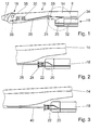
- a wiper arm 10 has a fastening part 12 which has a Hinged joint 16 is pivotally connected to a joint part 14 is.
- the hinge 16 has a hinge pin 38, the corresponding bearing holes in the fastening part 12 and the joint part 14 is mounted.
- To the Wiper arm 10 is a wiper blade 18 articulated, the side of the Joint part 14 runs and a non-iron wiper strip carrier 34 has, on which a wiper strip 32 is attached.
- an end clip 20 is on the wiper strip support attached.
- the end clip 20 has a cone-shaped approach 24 with an eyelet 22 into which a leaf spring 26 engages.
- the width of the leaf spring 26 is significantly larger than the height so that it is in a direction perpendicular to one Vehicle window is very compliant while doing that Wiper blade 18 leads laterally stable.
- the leaf spring 26 is on the outside of the fastening part fastened in the vicinity of the folding joint by means of a holder 30, e.g. by riveting, screwing, soldering, welding, gluing or the like.
- a holder 30 e.g. by riveting, screwing, soldering, welding, gluing or the like.
- the leaf spring 26 can also have its end 36 on the fastening part 12 or be attached to the hinge pin 38.
- the attachment on the hinge pin 38 is particularly suitable for the Use case when the wiper blade 18 is within a U-shaped Profile of the fastening part 12 runs.
- the end 36 of the leaf spring 26 can be wound around the hinge pin 38 be and on the top cover of the u-shaped Support profiles.
- Fig. 3 shows an embodiment in which the leaf spring 26 is formed by a spring tongue 40 which on the joint part 14 is molded. This can be done with sheet metal fasteners 12 can be achieved by suitable punching and bending processes. In the case of fastening parts 12 made of plastic, spring tongues of this type can be used 40 are injected or injected.
Landscapes
- Engineering & Computer Science (AREA)
- Mechanical Engineering (AREA)
- Clamps And Clips (AREA)
- Cleaning In General (AREA)
- Springs (AREA)
- Connection Of Plates (AREA)
Abstract
Description
- Fig. 1
- eine teilweise Seitenansicht eines Wischarms mit einem Wischblatt,
- Fig. 2
- eine vergrößerte Ansicht von oben auf einen Bereich II in Fig. 1 und
- Fig. 3
- eine Variante zu Fig. 2.
- 10
- Wischarm
- 12
- Befestigungsteil
- 14
- Gelenkteil
- 16
- Abklappgelenk
- 18
- Wischblatt
- 20
- Endklipp
- 22
- Öse
- 24
- zapfenförmiger Ansatz
- 26
- Blattfeder
- 28
- hakenförmiges Ende
- 30
- Halter
- 32
- Wischleiste
- 34
- Wischleistenträger
- 36
- Ende
- 38
- Gelenkbolzen
- 40
- Federzunge
Claims (5)
- Vorrichtung zum seitlichen Führen eines Wischblatts (18), das einen Wischleistenträger (34) mit einer Wischleiste (32) umfasst, dadurch gekennzeichnet, dass sie einen Klipp (20) mit einer Öse (22) aufweist, der auf dem Wischleistenträger (34) und/oder der Wischleiste (32) zu befestigen ist und in dessen Öse (22) eine Blattfeder (26) mit einem hakenförmigen Ende (28) greift, während ihr anderes Ende (36) an einem Teil eines Wischarms (10) zu befestigen ist.
- Vorrichtung nach Anspruch 1, dadurch gekennzeichnet, dass der Klipp ein Endklipp (20) ist und in seinem oberen Bereich einen zapfenförmigen Ansatz (24) mit der Öse (22) besitzt, der in Richtung eines Befestigungsteils (12) weist, wobei die Blattfeder (26) im Bereich eines Abklappgelenks (16) an dem Befestigungsteil (12), einem Gelenkteil (14) oder einem Gelenkbolzen (38) zu befestigen ist.
- Vorrichtung nach Anspruch 2, dadurch gekennzeichnet, dass das Wischblatt (18) seitlich des Gelenkteils (14) verläuft, wobei die Blattfeder (26) außen am Gelenkteil (14) zu befestigen ist.
- Vorrichtung- nach Anspruch 2, dadurch gekennzeichnet, dass, das Wischblatt (18) bügelfrei ist und eines seiner Enden weit gehend innerhalb des Gelenkteils (14) verläuft, wobei die Blattfeder (26) innen am Gelenkteil (14) zu befestigen ist.
- Vorrichtung nach einem der vorhergehenden Ansprüche, dadurch gekennzeichnet, dass die Blattfeder (26) von einer Federzunge (40) gebildet ist, die am Gelenkteil (14) angeformt ist.
Applications Claiming Priority (2)
| Application Number | Priority Date | Filing Date | Title |
|---|---|---|---|
| DE2002118034 DE10218034A1 (de) | 2002-04-23 | 2002-04-23 | Vorrichtung zum seitlichen Führen eines Wischblatts |
| DE10218034 | 2002-04-23 |
Publications (3)
| Publication Number | Publication Date |
|---|---|
| EP1357005A2 true EP1357005A2 (de) | 2003-10-29 |
| EP1357005A3 EP1357005A3 (de) | 2005-03-02 |
| EP1357005B1 EP1357005B1 (de) | 2006-08-30 |
Family
ID=28685247
Family Applications (1)
| Application Number | Title | Priority Date | Filing Date |
|---|---|---|---|
| EP20030006456 Expired - Lifetime EP1357005B1 (de) | 2002-04-23 | 2003-03-21 | Vorrichtung zum seitlichen Führen eines Wischblatts |
Country Status (3)
| Country | Link |
|---|---|
| EP (1) | EP1357005B1 (de) |
| DE (2) | DE10218034A1 (de) |
| ES (1) | ES2269849T3 (de) |
Citations (3)
| Publication number | Priority date | Publication date | Assignee | Title |
|---|---|---|---|---|
| DE3744237A1 (de) | 1987-12-24 | 1989-07-06 | Swf Auto Electric Gmbh | Scheibenwischer und fuehrungselement fuer einen scheibenwischer |
| DE19731683A1 (de) | 1997-07-23 | 1999-01-28 | Bosch Gmbh Robert | Scheibenwischer |
| DE19738232A1 (de) | 1997-09-02 | 1999-03-04 | Bosch Gmbh Robert | Tragelement für eine zu einem Wischblatt für Scheiben von Kraftfahrzeugen gehörenden Wischleiste und Verfahren zu dessen Herstellung |
Family Cites Families (2)
| Publication number | Priority date | Publication date | Assignee | Title |
|---|---|---|---|---|
| DE19605428A1 (de) * | 1996-02-14 | 1997-08-21 | Bayerische Motoren Werke Ag | Scheibenwischer mit Wischblatt-Stützeinrichtung |
| DE10103889A1 (de) * | 2001-01-30 | 2002-08-22 | Bosch Gmbh Robert | Wischarm mit einem gelenkig verbundenen Wischblatt |
-
2002
- 2002-04-23 DE DE2002118034 patent/DE10218034A1/de not_active Ceased
-
2003
- 2003-03-21 ES ES03006456T patent/ES2269849T3/es not_active Expired - Lifetime
- 2003-03-21 EP EP20030006456 patent/EP1357005B1/de not_active Expired - Lifetime
- 2003-03-21 DE DE50304809T patent/DE50304809D1/de not_active Expired - Lifetime
Patent Citations (3)
| Publication number | Priority date | Publication date | Assignee | Title |
|---|---|---|---|---|
| DE3744237A1 (de) | 1987-12-24 | 1989-07-06 | Swf Auto Electric Gmbh | Scheibenwischer und fuehrungselement fuer einen scheibenwischer |
| DE19731683A1 (de) | 1997-07-23 | 1999-01-28 | Bosch Gmbh Robert | Scheibenwischer |
| DE19738232A1 (de) | 1997-09-02 | 1999-03-04 | Bosch Gmbh Robert | Tragelement für eine zu einem Wischblatt für Scheiben von Kraftfahrzeugen gehörenden Wischleiste und Verfahren zu dessen Herstellung |
Also Published As
| Publication number | Publication date |
|---|---|
| DE50304809D1 (de) | 2006-10-12 |
| ES2269849T3 (es) | 2007-04-01 |
| EP1357005A3 (de) | 2005-03-02 |
| EP1357005B1 (de) | 2006-08-30 |
| DE10218034A1 (de) | 2003-11-13 |
Similar Documents
| Publication | Publication Date | Title |
|---|---|---|
| EP1363816B1 (de) | Wischarm mit einem gelenkig verbundenen wischblatt | |
| EP0928263B1 (de) | Scheibenwischer | |
| DE4439109B4 (de) | Mit einer Windleitvorrichtung komplettierbares Wischblatt | |
| EP1501710B1 (de) | Wischblatt | |
| EP2271524B1 (de) | Vorrichtung zum gelenkigen verbinden eines wischblatts mit einem wischarm | |
| WO2003045746A1 (de) | Wischblatt | |
| WO2007042377A1 (de) | Scheibenwischerarm | |
| DE10142997A1 (de) | Wischarm mit einem gelenkig verbundenen Wischblatt | |
| WO2005054017A2 (de) | Wischarm sowie abdeckeinheit für einen wischarm | |
| EP1485279B1 (de) | Vorrichtung zum seitlichen f hren eines wischblatts | |
| WO2015071104A1 (de) | Scheibenwischvorrichtung | |
| DE69206329T2 (de) | Scheibenwischer für ein Kraftfahrzeug, versehen mit einem aerodynamischen Windabweiser. | |
| DE69303106T2 (de) | Windableiter für Scheibenwischvorrichtung mit abnehmbarer weicher Kante | |
| DE102011082676A1 (de) | Scheibenwischer und Tragelement einer Wischleiste | |
| DE10106235A1 (de) | Wischarm | |
| DE69308792T2 (de) | Scheibenwischer mit aerodynamischem Zusatzgerät | |
| EP1357005A2 (de) | Vorrichtung zum seitlichen Führen eines Wischblatts | |
| DE69609575T2 (de) | Scheibenwischerblatt mit Mittel zum Befestigen von Zubehör und Scheibenwischer mit einem solchen Blatt | |
| DE112014005272T5 (de) | Verriegelungskopplung für Scheibenwischeranlage | |
| DE10150632A1 (de) | Verfahren zum Herstellen eines Wischarms | |
| EP0999105B1 (de) | Scheibenwischer mit austauschbarem Wischergummi | |
| DE19805461A1 (de) | Wischarm | |
| EP3044049B1 (de) | Scheibenwischvorrichtung mit verbessertem kriechverhalten | |
| DE10326007A1 (de) | Einrichtung zum Anheben eines in eine Parkstellung verfahrbaren Scheibenwischers | |
| DE102006058226A1 (de) | Baugruppe zur fahrzeugseitigen Befestigung eines Gurtschlosses |
Legal Events
| Date | Code | Title | Description |
|---|---|---|---|
| PUAI | Public reference made under article 153(3) epc to a published international application that has entered the european phase |
Free format text: ORIGINAL CODE: 0009012 |
|
| AK | Designated contracting states |
Kind code of ref document: A2 Designated state(s): AT BE BG CH CY CZ DE DK EE ES FI FR GB GR HU IE IT LI LU MC NL PT RO SE SI SK TR |
|
| AX | Request for extension of the european patent |
Extension state: AL LT LV MK |
|
| PUAL | Search report despatched |
Free format text: ORIGINAL CODE: 0009013 |
|
| AK | Designated contracting states |
Kind code of ref document: A3 Designated state(s): AT BE BG CH CY CZ DE DK EE ES FI FR GB GR HU IE IT LI LU MC NL PT RO SE SI SK TR |
|
| AX | Request for extension of the european patent |
Extension state: AL LT LV MK |
|
| 17P | Request for examination filed |
Effective date: 20050902 |
|
| AKX | Designation fees paid |
Designated state(s): DE ES FR GB IT |
|
| GRAP | Despatch of communication of intention to grant a patent |
Free format text: ORIGINAL CODE: EPIDOSNIGR1 |
|
| GRAS | Grant fee paid |
Free format text: ORIGINAL CODE: EPIDOSNIGR3 |
|
| GRAA | (expected) grant |
Free format text: ORIGINAL CODE: 0009210 |
|
| AK | Designated contracting states |
Kind code of ref document: B1 Designated state(s): DE ES FR GB IT |
|
| PG25 | Lapsed in a contracting state [announced via postgrant information from national office to epo] |
Ref country code: IT Free format text: LAPSE BECAUSE OF FAILURE TO SUBMIT A TRANSLATION OF THE DESCRIPTION OR TO PAY THE FEE WITHIN THE PRESCRIBED TIME-LIMIT;WARNING: LAPSES OF ITALIAN PATENTS WITH EFFECTIVE DATE BEFORE 2007 MAY HAVE OCCURRED AT ANY TIME BEFORE 2007. THE CORRECT EFFECTIVE DATE MAY BE DIFFERENT FROM THE ONE RECORDED. Effective date: 20060830 |
|
| REG | Reference to a national code |
Ref country code: GB Ref legal event code: FG4D Free format text: NOT ENGLISH |
|
| REF | Corresponds to: |
Ref document number: 50304809 Country of ref document: DE Date of ref document: 20061012 Kind code of ref document: P |
|
| ET | Fr: translation filed | ||
| GBT | Gb: translation of ep patent filed (gb section 77(6)(a)/1977) |
Effective date: 20070208 |
|
| REG | Reference to a national code |
Ref country code: ES Ref legal event code: FG2A Ref document number: 2269849 Country of ref document: ES Kind code of ref document: T3 |
|
| PLBE | No opposition filed within time limit |
Free format text: ORIGINAL CODE: 0009261 |
|
| STAA | Information on the status of an ep patent application or granted ep patent |
Free format text: STATUS: NO OPPOSITION FILED WITHIN TIME LIMIT |
|
| 26N | No opposition filed |
Effective date: 20070531 |
|
| PGFP | Annual fee paid to national office [announced via postgrant information from national office to epo] |
Ref country code: GB Payment date: 20090324 Year of fee payment: 7 |
|
| PGFP | Annual fee paid to national office [announced via postgrant information from national office to epo] |
Ref country code: IT Payment date: 20090326 Year of fee payment: 7 |
|
| PGFP | Annual fee paid to national office [announced via postgrant information from national office to epo] |
Ref country code: FR Payment date: 20090318 Year of fee payment: 7 |
|
| GBPC | Gb: european patent ceased through non-payment of renewal fee |
Effective date: 20100321 |
|
| REG | Reference to a national code |
Ref country code: FR Ref legal event code: ST Effective date: 20101130 |
|
| PG25 | Lapsed in a contracting state [announced via postgrant information from national office to epo] |
Ref country code: FR Free format text: LAPSE BECAUSE OF NON-PAYMENT OF DUE FEES Effective date: 20100331 |
|
| PG25 | Lapsed in a contracting state [announced via postgrant information from national office to epo] |
Ref country code: GB Free format text: LAPSE BECAUSE OF NON-PAYMENT OF DUE FEES Effective date: 20100321 Ref country code: IT Free format text: LAPSE BECAUSE OF NON-PAYMENT OF DUE FEES Effective date: 20100321 |
|
| REG | Reference to a national code |
Ref country code: DE Ref legal event code: R084 Ref document number: 50304809 Country of ref document: DE |
|
| PGFP | Annual fee paid to national office [announced via postgrant information from national office to epo] |
Ref country code: ES Payment date: 20200421 Year of fee payment: 18 |
|
| REG | Reference to a national code |
Ref country code: ES Ref legal event code: FD2A Effective date: 20220523 |
|
| PG25 | Lapsed in a contracting state [announced via postgrant information from national office to epo] |
Ref country code: ES Free format text: LAPSE BECAUSE OF NON-PAYMENT OF DUE FEES Effective date: 20210322 |
|
| PGFP | Annual fee paid to national office [announced via postgrant information from national office to epo] |
Ref country code: DE Payment date: 20220525 Year of fee payment: 20 |
|
| REG | Reference to a national code |
Ref country code: DE Ref legal event code: R071 Ref document number: 50304809 Country of ref document: DE |