EP1355456A1 - FlexRay communication protocol - Google Patents
FlexRay communication protocol Download PDFInfo
- Publication number
- EP1355456A1 EP1355456A1 EP02008171A EP02008171A EP1355456A1 EP 1355456 A1 EP1355456 A1 EP 1355456A1 EP 02008171 A EP02008171 A EP 02008171A EP 02008171 A EP02008171 A EP 02008171A EP 1355456 A1 EP1355456 A1 EP 1355456A1
- Authority
- EP
- European Patent Office
- Prior art keywords
- frame
- node
- communication
- cycle
- req
- Prior art date
- Legal status (The legal status is an assumption and is not a legal conclusion. Google has not performed a legal analysis and makes no representation as to the accuracy of the status listed.)
- Withdrawn
Links
- 238000004891 communication Methods 0.000 title claims abstract description 551
- 230000003068 static effect Effects 0.000 claims abstract description 215
- 238000000034 method Methods 0.000 claims abstract description 79
- 238000004590 computer program Methods 0.000 claims abstract 4
- 108091006146 Channels Proteins 0.000 description 255
- 238000012937 correction Methods 0.000 description 240
- 239000000872 buffer Substances 0.000 description 162
- 239000013598 vector Substances 0.000 description 90
- 230000005540 biological transmission Effects 0.000 description 85
- 230000007246 mechanism Effects 0.000 description 78
- 238000005259 measurement Methods 0.000 description 63
- 230000007704 transition Effects 0.000 description 50
- 230000000694 effects Effects 0.000 description 49
- 238000001914 filtration Methods 0.000 description 46
- 230000001360 synchronised effect Effects 0.000 description 44
- 238000004422 calculation algorithm Methods 0.000 description 36
- 230000003287 optical effect Effects 0.000 description 35
- 238000001514 detection method Methods 0.000 description 32
- 230000006399 behavior Effects 0.000 description 27
- 238000003745 diagnosis Methods 0.000 description 27
- 238000004364 calculation method Methods 0.000 description 26
- 238000010586 diagram Methods 0.000 description 23
- 230000010354 integration Effects 0.000 description 23
- 230000006870 function Effects 0.000 description 18
- 230000009977 dual effect Effects 0.000 description 17
- 230000008569 process Effects 0.000 description 17
- 238000012546 transfer Methods 0.000 description 16
- 230000003247 decreasing effect Effects 0.000 description 15
- 238000007726 management method Methods 0.000 description 15
- 230000008859 change Effects 0.000 description 14
- 230000001960 triggered effect Effects 0.000 description 12
- 238000012544 monitoring process Methods 0.000 description 10
- 230000000873 masking effect Effects 0.000 description 9
- 125000004122 cyclic group Chemical group 0.000 description 8
- 230000000737 periodic effect Effects 0.000 description 8
- 230000011664 signaling Effects 0.000 description 8
- 230000001934 delay Effects 0.000 description 7
- 238000013461 design Methods 0.000 description 7
- 239000011159 matrix material Substances 0.000 description 7
- 238000005070 sampling Methods 0.000 description 7
- 238000010200 validation analysis Methods 0.000 description 7
- 238000004806 packaging method and process Methods 0.000 description 6
- 230000006833 reintegration Effects 0.000 description 6
- 230000004044 response Effects 0.000 description 6
- 238000013459 approach Methods 0.000 description 5
- 230000001174 ascending effect Effects 0.000 description 5
- 238000012790 confirmation Methods 0.000 description 5
- 238000003708 edge detection Methods 0.000 description 5
- 238000012986 modification Methods 0.000 description 5
- 230000004048 modification Effects 0.000 description 5
- 230000000630 rising effect Effects 0.000 description 5
- 238000012360 testing method Methods 0.000 description 5
- 230000008901 benefit Effects 0.000 description 4
- 239000012634 fragment Substances 0.000 description 4
- 230000000977 initiatory effect Effects 0.000 description 4
- 230000002829 reductive effect Effects 0.000 description 4
- 239000013078 crystal Substances 0.000 description 3
- 238000013016 damping Methods 0.000 description 3
- 238000009826 distribution Methods 0.000 description 3
- 101100110009 Caenorhabditis elegans asd-2 gene Proteins 0.000 description 2
- 230000006978 adaptation Effects 0.000 description 2
- 230000015572 biosynthetic process Effects 0.000 description 2
- 230000001419 dependent effect Effects 0.000 description 2
- 230000003993 interaction Effects 0.000 description 2
- 238000000691 measurement method Methods 0.000 description 2
- 239000000203 mixture Substances 0.000 description 2
- 239000010453 quartz Substances 0.000 description 2
- 238000011084 recovery Methods 0.000 description 2
- 230000002441 reversible effect Effects 0.000 description 2
- VYPSYNLAJGMNEJ-UHFFFAOYSA-N silicon dioxide Inorganic materials O=[Si]=O VYPSYNLAJGMNEJ-UHFFFAOYSA-N 0.000 description 2
- 230000002269 spontaneous effect Effects 0.000 description 2
- 230000002123 temporal effect Effects 0.000 description 2
- 101710201354 Metallothionein A Proteins 0.000 description 1
- 101710094503 Metallothionein-1 Proteins 0.000 description 1
- 235000015429 Mirabilis expansa Nutrition 0.000 description 1
- 244000294411 Mirabilis expansa Species 0.000 description 1
- 238000009825 accumulation Methods 0.000 description 1
- 230000009471 action Effects 0.000 description 1
- 230000015556 catabolic process Effects 0.000 description 1
- 239000000919 ceramic Substances 0.000 description 1
- 238000006243 chemical reaction Methods 0.000 description 1
- 239000003795 chemical substances by application Substances 0.000 description 1
- 239000003086 colorant Substances 0.000 description 1
- 239000012141 concentrate Substances 0.000 description 1
- 238000005520 cutting process Methods 0.000 description 1
- 230000009849 deactivation Effects 0.000 description 1
- 230000007423 decrease Effects 0.000 description 1
- 230000007547 defect Effects 0.000 description 1
- 238000006731 degradation reaction Methods 0.000 description 1
- 238000012217 deletion Methods 0.000 description 1
- 230000037430 deletion Effects 0.000 description 1
- 230000014155 detection of activity Effects 0.000 description 1
- 230000006866 deterioration Effects 0.000 description 1
- 238000011161 development Methods 0.000 description 1
- 238000002592 echocardiography Methods 0.000 description 1
- 238000011156 evaluation Methods 0.000 description 1
- 238000009432 framing Methods 0.000 description 1
- 230000036039 immunity Effects 0.000 description 1
- 230000002401 inhibitory effect Effects 0.000 description 1
- 230000034184 interaction with host Effects 0.000 description 1
- 238000011835 investigation Methods 0.000 description 1
- 230000000670 limiting effect Effects 0.000 description 1
- 238000004519 manufacturing process Methods 0.000 description 1
- 235000013536 miso Nutrition 0.000 description 1
- 239000013307 optical fiber Substances 0.000 description 1
- 230000008520 organization Effects 0.000 description 1
- 230000036961 partial effect Effects 0.000 description 1
- 238000012913 prioritisation Methods 0.000 description 1
- 238000012545 processing Methods 0.000 description 1
- 239000000047 product Substances 0.000 description 1
- 230000001902 propagating effect Effects 0.000 description 1
- 238000012797 qualification Methods 0.000 description 1
- 238000001303 quality assessment method Methods 0.000 description 1
- 230000007420 reactivation Effects 0.000 description 1
- 230000000717 retained effect Effects 0.000 description 1
- 238000000926 separation method Methods 0.000 description 1
- 229910052710 silicon Inorganic materials 0.000 description 1
- 239000010703 silicon Substances 0.000 description 1
- 238000004088 simulation Methods 0.000 description 1
- 238000000638 solvent extraction Methods 0.000 description 1
- 239000013589 supplement Substances 0.000 description 1
- 230000008093 supporting effect Effects 0.000 description 1
- 230000001052 transient effect Effects 0.000 description 1
- 238000009827 uniform distribution Methods 0.000 description 1
- 230000002618 waking effect Effects 0.000 description 1
Images


Classifications
-
- H—ELECTRICITY
- H04—ELECTRIC COMMUNICATION TECHNIQUE
- H04L—TRANSMISSION OF DIGITAL INFORMATION, e.g. TELEGRAPHIC COMMUNICATION
- H04L12/00—Data switching networks
- H04L12/28—Data switching networks characterised by path configuration, e.g. LAN [Local Area Networks] or WAN [Wide Area Networks]
- H04L12/44—Star or tree networks
-
- H—ELECTRICITY
- H03—ELECTRONIC CIRCUITRY
- H03M—CODING; DECODING; CODE CONVERSION IN GENERAL
- H03M13/00—Coding, decoding or code conversion, for error detection or error correction; Coding theory basic assumptions; Coding bounds; Error probability evaluation methods; Channel models; Simulation or testing of codes
- H03M13/37—Decoding methods or techniques, not specific to the particular type of coding provided for in groups H03M13/03 - H03M13/35
- H03M13/43—Majority logic or threshold decoding
-
- H—ELECTRICITY
- H04—ELECTRIC COMMUNICATION TECHNIQUE
- H04L—TRANSMISSION OF DIGITAL INFORMATION, e.g. TELEGRAPHIC COMMUNICATION
- H04L12/00—Data switching networks
- H04L12/64—Hybrid switching systems
- H04L12/6418—Hybrid transport
-
- H—ELECTRICITY
- H03—ELECTRONIC CIRCUITRY
- H03M—CODING; DECODING; CODE CONVERSION IN GENERAL
- H03M13/00—Coding, decoding or code conversion, for error detection or error correction; Coding theory basic assumptions; Coding bounds; Error probability evaluation methods; Channel models; Simulation or testing of codes
- H03M13/03—Error detection or forward error correction by redundancy in data representation, i.e. code words containing more digits than the source words
- H03M13/05—Error detection or forward error correction by redundancy in data representation, i.e. code words containing more digits than the source words using block codes, i.e. a predetermined number of check bits joined to a predetermined number of information bits
- H03M13/09—Error detection only, e.g. using cyclic redundancy check [CRC] codes or single parity bit
-
- H—ELECTRICITY
- H04—ELECTRIC COMMUNICATION TECHNIQUE
- H04J—MULTIPLEX COMMUNICATION
- H04J3/00—Time-division multiplex systems
- H04J3/02—Details
- H04J3/06—Synchronising arrangements
- H04J3/0635—Clock or time synchronisation in a network
- H04J3/0638—Clock or time synchronisation among nodes; Internode synchronisation
- H04J3/0652—Synchronisation among time division multiple access [TDMA] nodes, e.g. time triggered protocol [TTP]
-
- H—ELECTRICITY
- H04—ELECTRIC COMMUNICATION TECHNIQUE
- H04L—TRANSMISSION OF DIGITAL INFORMATION, e.g. TELEGRAPHIC COMMUNICATION
- H04L12/00—Data switching networks
- H04L12/28—Data switching networks characterised by path configuration, e.g. LAN [Local Area Networks] or WAN [Wide Area Networks]
- H04L12/40—Bus networks
- H04L2012/40208—Bus networks characterized by the use of a particular bus standard
- H04L2012/40241—Flexray
-
- H—ELECTRICITY
- H04—ELECTRIC COMMUNICATION TECHNIQUE
- H04L—TRANSMISSION OF DIGITAL INFORMATION, e.g. TELEGRAPHIC COMMUNICATION
- H04L12/00—Data switching networks
- H04L12/64—Hybrid switching systems
- H04L12/6418—Hybrid transport
- H04L2012/6432—Topology
- H04L2012/6435—Bus
-
- H—ELECTRICITY
- H04—ELECTRIC COMMUNICATION TECHNIQUE
- H04L—TRANSMISSION OF DIGITAL INFORMATION, e.g. TELEGRAPHIC COMMUNICATION
- H04L12/00—Data switching networks
- H04L12/64—Hybrid switching systems
- H04L12/6418—Hybrid transport
- H04L2012/6432—Topology
- H04L2012/644—Star
-
- H—ELECTRICITY
- H04—ELECTRIC COMMUNICATION TECHNIQUE
- H04L—TRANSMISSION OF DIGITAL INFORMATION, e.g. TELEGRAPHIC COMMUNICATION
- H04L12/00—Data switching networks
- H04L12/64—Hybrid switching systems
- H04L12/6418—Hybrid transport
- H04L2012/6445—Admission control
- H04L2012/6459—Multiplexing, e.g. TDMA, CDMA
Definitions
- the communication protocol for the dependable automotive network described in this document has the following properties:
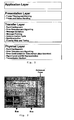
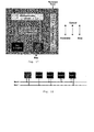
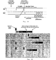
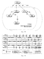
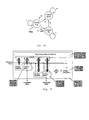
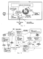
- FIG. 2 shows the architecture of a node (ECU). Every node consists of the five sub-components host, communication controller, bus guardian, bus driver, and power supply. This specification describes the requirements for the communication controller, the bus guardian, the bus driver and the interfaces to the host and the power supply. Two implementations for the communication controller are possible, one configuration of a communication controller that sends and receives on two redundant physical channels, and a second configuration which is solely connected to one physical channel.
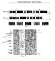
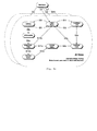
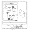
- FIG 3 shows the possible topology configuration of the communication network.
- a node can either be connected to both channels 1 and 2 (node A, C, and E) or only channel 1 (node B) or only channel 2 (node D).
- a configuration, where all nodes are connected by 1 channel only is also possible.
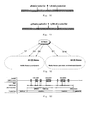
- Communication is done in a communication cycle consisting of a static and a dynamic segment, where each of the segments may be empty.
- the first frame ID in a system with a static segment is ID number 1 (see Figure 4).
- the sending slots are represented through the ID numbers that are the same on both channels.
- the sending slots are used deterministically (in a pre-defined TDMA strategy) in the static segment.
- the dynamic segment there can be differences in the phase on the two channels (see Figure 4). Nodes that are connected to both channels send their frames in the static segment simultaneously on both channels. Two nodes, that are connected to one channel only, but not the same channel, may share a slot in the static segment.
- nodes can participate that send frames, which are received by all other nodes (e.g., node A, C and E in Figure 3). All nodes execute the clock synchronization algorithm, but only the frames of the static segment are considered. It is possible to send different data in the same sending slot on different channels.
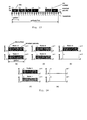
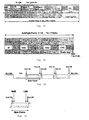
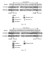
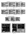
- Figure 7 shows the FlexRay frame format
- Figure 8 shows the byteflight frame format.
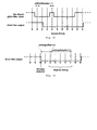
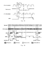
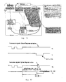
- Figure 9 shows the transmission of the start sequence. Due to certain effects in the optical transmission, it is possible for the start sequence to be become shorter or longer during optical transmission. This is why the receiver accepts start sequences in the region of 1-9 logical "0" bits. This is illustrated by the following diagram in Figure 10 .
- Figure 10 shows the reception of the start sequence.
- Figure 11 shows the frame format for electrical transmission.
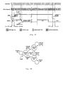
- Figure 12 shows an example of a topology of a FlexRay network using active stars.
- Figure 13 shows an example of a topology of a FlexRay network using a passive bus.
- Figure 14 shows an example of a topology of a FlexRay network using an active star combined with a passive bus.
- Each node must adhere to the following requirements:
- Figure 15 shows a block chart of a FlexRay node. Each active star must adhere to the following requirements:
- Figure 16 shows a block chart of an electrical active star.
- the chapter summarises the requirements on the communication controller and the bus driver to run an ECU in several modes.
- the bus driver has to support several states or operating modes:
- the communication system and its components shall offer adequate error management mechanisms to deal with faults arising from the following levels:
- the following faults have at least to be detected by the communication controller:
- CONTROLLER_MAX 64 Maximum number of controllers connected to one communication channel. CYCLE_LENGTH_MIN 250 ⁇ s Minimum length of the configurable communication cycle. CYCLE_LENGTH_MAX 64 ms Maximum length of the configurable communication cycle. DATA_BYTES_MAX 246 Maximum number of data bytes. DYNAMIC_IDS 4095 Maximum number of dynamic identifiers. STATIC_SLOTS_MIN 2 Minimum number of static slots in a static segment of a communication cycle STATIC_SLOTS_MAX 4095 Maximum number of static slots in a static segment of a communication cycle
- the owner of the PWD is the FlexRay consortium. Members are BMW, DaimlerChrysler, Philips, Bosch, General Motors and Motorola. All of these companies deliver input to the appendix but only one editor (Motorola) handles the inclusion in the document.
- gName Global Parameter parameter which must have the same value in all nodes in a cluster, is initialized during soft reset, can only be changed during soft reset
- pName Local Parameter parameter which may differ in nodes of a cluster, is initialized during soft reset, can only be changed during soft reset
- fName-variables are set in the transmitter node and read in the receiver node
- xdName Time Duration value (variable, parameter, etc.) describing a time duration, time between two time points xtName Time value (variable, constant, etc.) describing a instant xsName Set set of values (variables, parameters, etc.)
- x stands for one of c, v, g, or p
- a network can be configured as a single-channel or dual-channel bus network, a single-channel or dual-channel star network.
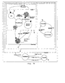
- Figure 18 shows the possible topology configuration of the communication network as a dual bus.
- a node can either be connected to both channels 0 and 1 (nodes A, C, and E), only to channel 0 (node D) or only to channel 1 (node B).
- the FlexRay communication network can also be a single bus. In this case, all nodes are connected to this bus.
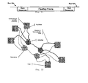
- a FlexRay communication network can be built as a multiple star topology. Similar to the bus topology, the multiple star topology can be set up redundantly. Each network channel must be free of closed rings, and there may only be 1 up to cStarCouplersMax sequentially connected (cascaded) star couplers (the total number of star couplers may be more than cStarCouplersMax if there are branches in the network). Each network line between communication node and the star coupler or between two star couplers represents a properly terminated point-to-point connection. The incoming signal received by the star coupler is actively driven to all communication nodes Figure 19 shows a single redundant star coupler configuration
- OpenTopic We assume that the star coupler drives all connected nodes and star couplers except the reception line. Also we assume that one a line erroneously driven by the star coupler and another instance will show a signal causing an encoding error in any case. We assume that other lines driven by the star coupler are not affected by such a conflict.
- Figure 20 shows a single channel network with three star couplers.
- FIG. 19 The configuration of a single redundant star network is shown in Figure 19 .
- the logical structure of this topology is identical with the logical bus structure shown in Figure 18 .
- a topology which has a single non-redundant star, which has the logical bus structure of the single bus mentioned above, is also possible.
- Figure 20 shows a single channel network built with three star couplers. Each node has a point-to-point-connection to one of the three star couplers. Two of the star couplers (No. 1 and 3) are directly connected to the third star coupler (No. 2).
- Open Topic Open topic: For the modeling project it is assumed that all connections of a star coupler are set up for reception per default. When the first bits (this time is called “configuration setup delay" and is configurable in the model) of a Frame Start sequence are detected on one receive line this causes the other receive lines to be reconfigured for transmission. A sequence of correctly encoded bits is assumed to cause this reconfiguration, though (pessimistic assumption). Noise does not cause this reconfiguration. If the condition for this reconfiguration is observed on two or more receive lines within a time window of 1 gdBit the star coupler generates a signal with illegal encoding on all other lines that will then be reconfigured as transmit lines. Actually in the model the same signal is generated like for a bus with overlapping frames. This reconfiguration remains until an idle signal is recognized on (all) the receive line(s). As soon as this is recognized all lines are reset to the default configuration.
- the point-to-point connection defines the minimum Frame Start sequence and so does make sense to include it in this table.
- Open Topic needs to be clarified, but probably isn't due to the different optical device characteristics.
- Detection Events detailed in Table 6 actually means 'Detectors' i.e. in a point to point or broadcast bus topology, there is only one detector - the receiving node - and no portion of the FSS is consumed, in a single star network, there are two detectors - star-coupler and receiving node - and the first of those will consume part of the Frame Start sequence, and so on.
- the point-to-point connection defines the minimum FSS.
- Maximum Frame Start Sequence Durations wrt Network Topology Network Topology Detection Events Frame Start Sequence [ns] e.g. number of gdBit @ 10 Mbps Point to point/Bus 1 200 2 Single Star 2 400 4 2 Cascaded Star Couplers (not supported FPGA V4) 3 600 6 3 Cascaded Star Couplers (not supported FPGA V4) 4 800 8
- Figure 21 shows an example of the architecture of a node. Every node consists of the four sub-components host, communication controller, bus guardian and physical driver. The sub-components may be discrete, or certain combinations of them may be integrated together e.g. bus guardian and physical layer (as shown) and host and communications controller.
- FlexRay media access is performed within a periodically recurring communication cycle.
- the structure of this communication cycle is described in this section.
- FlexRay offers the choice of two media access schemes. These are
- each segment is configurable.
- a pure static mode, a mixed mode containing a static as well as a dynamic scheme and a pure dynamic mode may be configured.
- Section "Static Segment (TDMA Access)" of the specification focuses on the static TDMA scheme and Section "Dynamic Segment” covers the dynamic mini-slotting based scheme.
- the FlexRay protocol offers the option of implementing clusters with a single communication channel (channel A only) or with dual communication channels (channel A and channel B).
- a dual channel cluster the channels are synchronized to one another.
- nodes may be connected to either one or both of the communication channels.
- Dual channel systems support nodes connected to only one of the communications channels of the cluster.
- Such single channel nodes can be connected to either channel A or channel B.
- the communication cycle is the fundamental element of the media access scheme within FlexRay.
- the communication cycle consists of a combination of two segments: a static segment and a dynamic segment.
- the communication cycle contains a static segment in
- TDMA Time Division Multiple Access
- Figure 23 shows the transmission slot layout within the static segment of the communication cycle.
- Figure 24 shows the basic media access patterns for two channels. (add explanation of figure here)
- Receive buffers are only updated in Normal Mode; receive buffers are not updated during startup.
- the communication cycle contains a dynamic segment in
- FTDMA time-division multiple access
- each node is engaged in one of three activities: waiting for a minislot in which it will transmit a frame, frame transmission, or monitoring channel activity and frame reception. These are described subsequently. Note that the following activities are performed independently for each communication channel.
- the dynamic segment terminates if either of the following two conditions is met:
- Receive buffers are only updated in Normal Mode; receive buffers are not updated during startup.
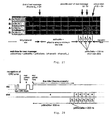
- Figure 25 shows distributed synchronized slot counters of nodes A and B.
- Node A sends the ID's 2, 4 and 5.
- Node B sends the ID's 1 and 3.
- the slot counters switch the value to 1 in all nodes - in this case, node B, since it has a transmit request for Frame ID 1, starts transmitting. If a node recognizes a bus activity, e.g.
- Bus activity detection is performed after the glitch filter. Bus activity is detected if at least one period of gdBit is recognized as bus active (The 1 * gdBit period of activity is equivalent to the minimum duration of the Frame Start Sequence). For a 2-State physical layer, bus activity equals the logical '0' level. For a 3-state physical layer, bus activity equals either a logical '0' or a logical '1' with the RX_enable signal active.
- Figure 26 shows the calculation of vdWaitTime after DCT.
- All slot counters in transmit slot 1 have a value of 1.
- the slot counters are incremented by one.
- Frame IDs 2 and 3 are now able to transmit. However, in this communication cycle no transmissions take place because there is no transmit request for these two frames.
- node B which in this case has a transmit request for Frame ID 4, starts transmitting.
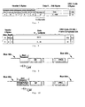
- the following diagrams are intended to explain the waiting time calculation after frame format errors. They all show the reception line (RX) and the slot counter (referred to as slot) of a node.
- Figure 28 shows the slot counter after a frame format error, in particular an example of a CRC error detected in the last CRC byte on a 2-State physical layer.
- the wait time vdWaitTime is started (at least hypothetically). Since activity is again detected on the bus before the slot counter is incremented, the wait time vdWaitTime is started again at the next ascending flank. In this case the time ( pdWx0Rx + pdWxDelta ) elapses without any further bus activity and the slot counter is increased by one. Transmitting and receiving is now possible again starting with slot 5.
- Figure 29 shows an example of what happens when the receiving device is able to detect an error some time after the last ascending flank of the error or of the frame fragment (slot counter after frame fragments). This is the case, for example, when using a optical physical layer with NRZ coding, if the receiving device expects the size of the frame (byteflight frame format) to be larger than it actually is because of a bit error in the data length field of the frame. The error can only be detected with the last missing stop bit, which is 10 * gdBit after the last rising flank. The same effect occurs if a frame fragment that looks like a valid Frame Start Sequence is detected on the receiving line. A format or coding error can only be discovered 10 * gdBit after the ascending flank because the frame fragment is accepted as a valid Frame Start Sequence and is only detected due to the missing stop bit.
- the waiting time vdWaitTime begins as soon as the error is detectable and the receive line has reached the bus inactive state.
- the duration of the network idle time is denoted gdNIT .
- the parameter gdNIT depends on the signal propagation delay, the clock synchronization execution time, and an additional time period that ensures the ability of a node to properly handle the reception of a frame that starts up to 0.5 * gdSlot before the first slot of the cycle begins.
- At least 2 static communication slots must be configured.
- At least 2 synchronization frames must be exchanged.
- the communication cycle contains the static segment, the dynamic segment and the network idle time.
- Some physical layers generate echoes of signals transmitted by the communication controller which may be seen with a certain delay on the Rx Input of the communication controller's receiver. For example, this may happen if a communication controller is connected directly to an electrical star without using a bus driver device or if the physical layer device features a loop back function which causes a significant delay (at least 0.5 * gdBit ).
- the Rx Pin should not be evaluated for that purpose during pdWx0Tx after the transmission of a message or a SOC symbol has ended.
- Figure 30 shows an externally triggered SOC.
- VdWaitTime calculation is based on uncorrected Microticks (V5). If a controller supports corrected microticks the parameter pdWxDelta could be minimized.
- This chapter describes the supported frame, symbol, and packet formats used by the FlexRay protocol.
- the first section focuses on the frame and symbol formats, the second section describes the packet format and the subsequent section describes the coding schemes.
- frame, packet and encoded packet is such that the frame is embedded in a packet before it is coded for the physical layer. This separation decouples the frame format from the format required on the physical layer. This decoupling allows the FlexRay protocol to make use of different physical layers that require distinct coding methods.
- the FlexRay protocol supports two distinct frame formats:
- All controllers in a cluster must be configured to use the same frame format. Specifically, a system in which some controllers use the FlexRay frame format while other controllers use the byteflight frame format is not a valid system configuration.
- the FlexRay frame format may be used for systems with pure static, pure dynamic, and mixed (static plus dynamic) media access methods.
- the byteflight frame format may only be used in systems operating in byteflight compatibility mode.
- Both frame formats contain a header segment, a payload segment and a trailer segment, each of which contains specific fields.
- the FlexRay protocol makes use of four distinct symbols. These symbols exist outside of the normal frame/packet formats.
- the FlexRay symbols are:
- the frame shall be transmitted on the network such that the header segment appears first, followed by the payload segment, and then followed by the trailer segment, which is transmitted last.
- the FlexRay header segment consists of 5 bytes that contain several distinct fields; two fields of reserved bits, the Frame ID, a Payload Length field, a Sync Bit, a Header CRC field, a Data Update Bit, and a Cycle Counter field. These fields are described in detail in the following sections.
- the fields shall be transmitted in the order indicated in Figure 31, moving from left to right (i.e., the Reserved 1 field is transmitted first and the Cycle Counter field is transmitted last).
- the Reserved 1 field shall be transmitted such that most significant bit of fAcknowLength is transmitted first.
- FPGA V5 does not support acknowledgement vectors.
- This field consists of two bits that are reserved for future protocol use. These bits shall not be used by the application.
- the Reserved 2 field shall be transmitted with both bits set to logical '0'. As the bits are identical, transmission order is not defined.
- This field contains the Frame Identifier for the frame.
- Each frame that may be transmitted in a cluster has a frame ID fFrameID assigned.
- the frame ID fFrameID is a unique number per communication channel per communication cycle and defines the slot in which the frame is transmitted
- Valid values for fFrameID range from (0000 0000 0001) 2 to (1111 1111 1111) 2 .
- the Frame ID field shall be transmitted such that the most significant bit of fFrameID is transmitted first with the remaining bits of fFrameID being transmitted in decreasing order of significance.
- Payload Length (7 bits - fPayloadLength )
- the payload length field does not include the number of bytes within the header and the trailer segments of the FlexRay frame.
- the maximum payload length is cPayloadLengthMax , which corresponds to a payload segment containing 2 * cPayloadLengthMax bytes.
- the payload field shall be less than or equal to the maximum payload length: fPayloadLength ⁇ cPayloadLengthMax .
- the payload length fPayloadLength may be different for different frames in the dynamic segment of a communication cycle.
- the payload length of a specific dynamic segment frame may vary from cycle to cycle.
- the payload lengths of a specific dynamic segment frame may be different on each configured channel. All dynamic segment frames, however, shall have 0 ⁇ fPayloadLength ⁇ cPayloadLengthMax.
- the Payload Length field shall be transmitted such that the most significant bit of fPayloadLength is transmitted first with the remaining bits of fPayloadLength being transmitted in decreasing order of significance.
- the sync bit fSyncBit determines whether the frame is to be used for clock synchronization.
- a node If a node transmits a given frame on more than one channel it shall set fSyncBit to the same value on each channel.
- Header CRC (9 bits - fHeaderCRC )
- the Header CRC field contains a Cyclic Redundancy Check code (CRC) computed over the Payload Length and Sync Bit fields of the frame.
- CRC Cyclic Redundancy Check code
- the CRC is computed in the same manner on all configured channels.
- the CRC polynomial (This 9 bit CRC polynomial generates a code that has a minimum Hamming distance of 6 for codewords up to 17 bits in length.
- the initialization vector of the header CRC shall be (1A) HEX .
- the Payload Length and Sync Bit fields shall be fed into the CRC generator in network order, specifically the most significant bit of the Payload Length field shall be shifted in first, followed by subsequent bits of the Payload Length, and then the Sync Bit field.
- the Header CRC field shall be transmitted such that the most significant bit of fHeaderCRC is transmitted first with the remaining bits of fHeaderCRC being transmitted in decreasing order of significance.
- the Cycle Counter field indicates the transmitting node's view of the cycle counter vCycle at the time of frame transmission
- the Cycle Counter field shall be transmitted such that the most significant bit of fCycleCount is transmitted first with the remaining bits of fCycleCount being transmitted in decreasing order of significance.
- the FlexRay payload segment contains 0 to 246 bytes of data written by the host.
- the FlexRay Payload Segment shall consist of an even number of bytes.
- the first two bytes of the FlexRay payload segment may optionally be used as a message ID field, allowing receiving nodes to filter or steer data based on the contents of this field.
- Future versions of the protocol may utilize certain bytes of the payload segment to implement an acknowledgement vector used in a protocol-level acknowledgement service.
- the individual bytes within the Payload Segment shall be transmitted such that the most significant bit of the byte is transmitted first with the remaining bits of the byte being transmitted in decreasing order of significance.
- the FlexRay trailer segment contains a single field, a 24-bit CRC for the frame.
- Frame CRC (24 bits - fFrameCRC )
- the Frame CRC field contains a Cyclic Redundancy Check code (CRC) computed over the Header and Payload segments of the frame.
- CRC Cyclic Redundancy Check code
- the computation includes all fields in these segments (This includes the header CRC, as well as any Communication Controller-generated "padding" bytes that may be included in the Payload segment.).
- the CRC is computed using the same generator polynomial on both channels.
- the CRC polynomial (This 24 bit CRC polynomial generates a code that has a minimum Hamming distance of 6 for codewords up to 2048 bits in length.
- the generation process of the CRC differs slightly depending on which channel the frame is being transmitted (Different initialization vectors are defined to prevent a node from communicating if it has crossed channels, connection of a single channel node to the wrong channel, or shorted channels (both controller channels connected to the same physical channel) in an easy and inexpensive way.):
- the frame fields shall be fed into the CRC generator in network order (that is, the first thing into the generator is the most significant bit of the Reserved 1 field, and the last thing into the generator is the least significant bit of the last byte of the Payload Segment).
- the Frame CRC field shall be transmitted such that the most significant bit of fFrameCRC is transmitted first with the remaining bits of fFrameCRC being transmitted in decreasing order of significance.
- the frame shall be transmitted on the network such that the header segment appears first, followed by the payload segment, and then followed by the trailer segment, which is transmitted last.
- the byteflight header segment consists of 2 bytes that contain several distinct fields; the Frame ID, a field of reserved bits, and the frame length. These fields are described in detail in the following sections.
- the fields shall be transmitted in the order indicated in Figure 32, moving from left to right (i.e., the Frame ID field is transmitted first and the Frame Length field is transmitted last).
- This field contains the Frame Identifier for the frame.
- Each frame that may be transmitted in a cluster has a frame ID fBfFrameID assigned.
- the frame ID fBfFrameID is a unique number per communication channel per communication cycle and defines the minislot in which the frame is transmitted Valid values for fBfFrameID range from (0000 0001) 2 to (1111 1111) 2 .
- the Frame ID field shall be transmitted such that the most significant bit of fBfFrameID is transmitted first with the remaining bits of fBfFrameID being transmitted in decreasing order of significance.
- This field consists of four bits that are reserved for future protocol use. These bits shall not be used by the application.
- the Reserved Bits field shall be transmitted with all bits set to logical '0'. As the bits are identical, transmission order is not defined.
- the Frame Length consists of a single parameter, fBfFrameLength , that indicates the number of data bytes that are contained in the payload segment of the frame.
- the frame length field does not include the number of bytes within the header and the trailer segment of the byteflight frame.
- a frame which is received with fBfFrameLength greater than 12 shall be treated as an error.
- the Frame Length field shall be transmitted such that the most significant bit of fBfFrameLength is transmitted first with the remaining bits of fBfFrameLength being transmitted in decreasing order of significance.
- the byteflight payload segment consists of 0 to 12 bytes of data written by the host.
- the individual bytes within the Payload Segment shall be transmitted such that the most significant bit of the byte is transmitted first with the remaining bits of the byte being transmitted in decreasing order of significance.
- the byteflight trailer segment consists of 2 bytes that contain two distinct fields; a Frame CRC and the Frame Completion Bit. These fields are described in detail in the following sections.
- the fields shall be transmitted in the order indicated in Figure 32, moving from left to right (i.e., the Frame CRC field is transmitted first and the Frame Completion Bit is transmitted last).
- the Frame CRC field contains a Cyclic Redundancy Check code (CRC) computed over the Header and Payload segments of the frame. The computation includes all fields in these segments.
- CRC Cyclic Redundancy Check code
- the CRC generator polynomial (This is the same polynomial as used in the CAN protocol as defined in International Standards Organization (1993). Road Vehicles - Interchange of Digital Information - Controller Area Network (CAN) for High Speed Communication. ISO11898, 1993. It is optimized for code words of up to 127 bits.) shall be x 15 + x 14 + x 10 + x 8 + x 7 + x 4 + x 3 + 1
- the initialization vector of the byteflight Frame CRC shall be (00) Hex .
- the frame fields shall be fed into the CRC generator in network order (that is, the first thing into the generator is the most significant bit of the Frame ID field, and the last thing into the generator is the least significant bit of the last byte of the Payload Segment)
- the Frame CRC field shall be transmitted such that the most significant bit of fBfFrameCRC is transmitted first with the remaining bits of fBfFrameCRC being transmitted in decreasing order of significance.
- the Frame Completion Bit, fBfFCB is a single bit whose sole purpose is to allow the byteflight frame to end on a byte boundary.
- the FlexRay protocol makes use of four distinct symbols.
- the FlexRay symbols are:
- the FlexRay protocol makes use of two distinct Start-of-Cycle symbol (SOC) symbols, an SOC Normal symbol and an SOC Alarm symbol. These symbols have the following definition:
- the SOC Normal and SOC Alarm symbols have the same duration (30* gdBit ), and both symbols start at the same point in time relative the beginning of a normal communication frame.
- the SOC Normal symbol is used in systems operating in the byteflight compatibility mode or in the FlexRay pure dynamic mode.
- the SOC Alarm symbol is only used in systems operating in the byteflight compatibility mode.
- the Collision Avoidance Symbol is used to minimize the possibility of collisions during the startup phase of FlexRay systems which feature a static segment (i.e., systems operating in the pure static or mixed static operating modes). Refer to the chapter "Startup" for further information.
- the Collision Avoidance Symbol shall have the same definition as the SOC Normal described in Section "SOC Symbols”.
- the Collision Avoidance Symbol is sent once during cold start before the first communication cycle in pure static or mixed static-dynamic FlexRay mode (for details see the “Start-up” and “Media Access Scheme” chapters).
- the Collision Avoidance Symbol shall not be used in systems operating in the FlexRay pure dynamic or byteflight compatibility modes.
- the Wake-up symbol is used to allow a node to transition from a low power consumption standby state to a state in which it is able to communicate (i.e., to "wake up") based solely on signals received on the communications link(s). Differences in the physical characteristics of the physical layers cause the existence of two distinct Wake-up symbols, one for the electrical physical layer and one for the optical physical layer.
- the Header CRC field of a FlexRay frame is intended to provide protection against improper modification of the Sync Bit field by a faulty communication controller (CC).
- the CC that is responsible for transmitting a particular frame shall not compute the Header CRC field for that frame. Rather, the CC shall be configured with the appropriate Header CRC for a given frame by the host. This makes it unlikely that a fault in the CC that causes the value of a Sync Bit to change would result in a frame that is accepted by other nodes in the network because the CRC would not match. This is possible because, for fixed length frames at least, the Header CRC would be constant. Removing the capability of the transmitter to generate the CRC minimizes the possibility that a CC fault would have a proper header CRC.
- the CC that is responsible for the reception of a frame shall perform the CRC computations required to check the correctness of the Header CRC field relative to the other information that is received in the frame.
- fDataUpdateBit The value of fDataUpdateBit in the message buffer is transmitted in every frame as it is stored in the message buffer.
- the first two bytes of the payload segment of the FlexRay frame format are receiver filterable data called Message ID.
- the Message ID is an application determinable number that describes the contents of the data segment.
- the Message ID is 16 bits long.
- the Message ID must be consistent in the whole cluster.
- the most significant bit of fMessageID shall be placed in the most significant bit of the first byte of the payload segment. Subsequent bits of fMessageID shall be placed in the next payload bits in order of decreasing significance.
- FPGA V5 does not support Message ID's. All bytes in the Payload segment of a FlexRay frame shall be treated as normal host-generated data bytes by both receiving and transmitting nodes.
- the third, fourth and fifth byte of the payload segment may be used as for acknowledgement information.
- These bytes may be used for acknowledgement information.
- the Acknowledgement Vector field shall be transmitted such that the most significant bit of fAcknowVector is transmitted first with the remaining bits of fAcknowVector being transmitted in decreasing order of significance.
- NRZ 8N1 This section describes the FlexRay coding method referred to as NRZ 8N1.
- the mechanism is given this name because it uses a Non-Return to Zero (NRZ) signaling method that uses symbols consisting of 8 data bits, no parity bits, and 1 stop bit (8N1).
- NRZ Non-Return to Zero
- This section describes the frame packaging. Packaging adds physical layer specific elements to frames.
- the additional information for NRZ 8N1 consists of the Frame Start Sequence (FSS).
- each frame shall begin with a Frame Start Sequence (FSS) consisting of 8 consecutive bits sent as logical "0".
- FSS Frame Start Sequence
- the FSS shall be transmitted without any start or stop bits.
- the FSS seen by a receiver may be shorter or even longer than the FSS that was sent by the transmitter. All receivers shall accept Frame Start Sequences with a duration of 1-9 bit times.
- Figure 33 shows the frame coding when using NRZ 8N1.
- the frame is composed of a Frame Start Sequence and an integral number of byte frames, each of which convey 8 bits of higher layer data.
- the NRZ 8N1 coding mechanism defines three distinct symbols; two different Start of Cycle (SOC) symbols, SOC Normal and SOC Alarm, and a Collision Avoidance Symbol (CAS). The coding of these symbols is described in the following sections.
- the SOC Normal symbol shall be transmitted as 10 gdBit times at a logical "1" level followed by 30 gdBit times at a logical "0" level as is shown in Figure 35.
- the receivers of an SOC Normal signal shall tolerate the following variations from the nominal definition of the signal:
- Version 5 Solution The preceding definition of the acceptance criteria of an SOC Normal symbol applies to the FPGA V5 implementation only. A different definition may be used in future versions of the protocol.
- the SOC Normal symbol is used in pure dynamic configurations for synchronization.
- the SOC Normal symbol is sent by a single configured master.
- the SOC Alarm symbol shall be transmitted as 20 gdBit times at a logical "1" level followed by 20 gdBit times at a logical "0" level as is shown in Figure 36.
- the receivers of an SOC Alarm signal shall tolerate the following variations from the nominal definition of the signal:
- Version 5 Solution The preceding definition of the acceptance criteria of an SOC Alarm symbol applies to the FPGA V5 implementation only. A different definition may be used in future versions of the protocol.
- the SOC Alarm symbol is used in pure dynamic configurations for synchronization (same functionality as SOC Normal).
- the SOC Alarm signal is sent by a single configured master (the same master that sends the SOC Normal signal).
- the SOC Alarm symbol can be used to indicate a different operation mode.
- SOC Alarm symbol is coded neither with start bits nor with stop bits. (Rationale: This is an intentional code violation of the NRZ 8N1 coding rules).
- the Collision Avoidance Symbol shall be encoded in the same manner as the SOC Normal symbol described in Section "SOC Normal Symbol”.
- Transmitters of the CAS have the same coding requirements as transmitters of the SOC Normal symbol.
- Receivers of the CAS have the same tolerance requirements as receivers of the SOC Normal signal.
- Collision Avoidance Symbol is used at startup in pure static and mixed static/dynamic configurations for collision avoidance (see “Startup” chapter for further details).
- the block diagram in Figure 37 shows the control flow of the receive and receive-enable signals through the glitch filter and sample voting mechanism.
- Glitch filtering is performed on the receive signals of all configured channels (RXDA and/or RXDB) and on the receive enable signals of all configured channels (RXEA and/or RXEB).
- Glitch filtering shall be performed by the following mechanism:
- the edge detection process shall be performed on the glitch filtered version of the receive and receive-enable signals (RXDA_F, RXDB_F, RXEA_F, RXEB_F).
- Edge detection is used for resynchronizing the bit sampling and voting process at the rising edge that results from the stop bit to start bit transition at the end of a byte.
- the edge detection process is also used to determine the end of an SOC or Collision Avoidance Symbol, and to detect the end of a frame in the dynamic part in order to start the slot counter mechanism.
- the sample voting process shall be performed on the glitch filter output of the receive signals (RXDA_F and/or RXDB_F).
- the sample voting process defines a "window" of samples that are used to make the determination of the value of a received bit.
- This window is characterized by two parameters, pVotingOffset and pVotingSamples . An example showing the relationship of these two parameters is shown in Figure 41.
- the parameter pVotingOffset specifies the offset of the start of the voting window from the start of the bit cell. This offset defines the first sample of the bit that will be considered for the voting.
- the pVotingSamples parameter specifies the number of samples in the voting window.
- the window is defined by taking pVotingSamples consecutive samples starting with the sample indicated by pVotingOffset.
- the bit value shall be determined by majority voting over the samples within the voting window (This implies that the number of samples within the voting window, pVotingSamples, must be odd.), i.e., if a majority of samples within the voting window have logical value "0", the output value of the sampled bit shall be "0"; if a majority of samples within the voting window have logical value "1” the output value of the sampled bit shall be "1".
- the voting window and the bit sampling shall be resynchronized with every start bit.
- FPGA V5 uses an 80 Mhz oscillator with a 12.5 ns oscillator period. FPGA V5 shall support the bit rates, prescalers, and sampling configurations defined in the following table. Index Sample Clock Prescaler Sample Clock Period (ns) Samples per Bit Bit Time (ns) Bit Rate (Mbps) 1 1 12.5 8 100 10.000 2 1 12.5 10 125 8.000 3 2 25.0 8 200 5.000 4 2 25.0 10 250 4.000 5 4 50.0 8 400 2.500 6 4 50.0 10 500 2.000 7 8 100.0 8 800 1.250 8 8 100.0 10 1000 1.000 9 16 200.0 8 1600 0.625 10 16 200.0 10 2000 0.500 System Constants, Parameters and Variables Name Description Range/Value Unit pSamplePeriod Time interval between two consecutive sampling points ns pGlitchSamples Number of samples that are filtered out by the glitch filter mechanism [0- pSamplesPerBit /2] pSamplesPerBit Number of samples per bit 8 or
- Proposal Use an up-down counter (integrator) that changes the detected value when the number of glitch samples is reached.
- every node has its own clock. Because of temperature and voltage changes and because of production tolerances of the timing source (normally quartz crystals are used) the internal time base diverges between the nodes after a short time, even if all internal time bases of the nodes are started concurrently.
- the timing source normally quartz crystals are used
- Every node in the cluster has the same view of time and this common global view of time is used as the local time base for each node.
- "the same” means that the differences between the nodes' views of the global time are bounded and that a maximum value for this difference can be guaranteed.
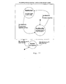
- FlexRay supports two methods for synchronization of the local time base. Which synchronization method is used depends on the configuration (see Figure 42).
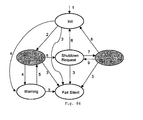
- Figure 42 shows the relation between the operation mode, media access and clock synchronization.
- Figure 44 shows the local timing of three nodes and their relation to each other.
- FlexRay node activities including communication, are based on the concept global time, even though each individual node maintains its own view of it. It is the clock synchronism mechanism differentiates the FlexRay cluster from other node collections with independent clock mechanisms.
- the global time is a vector of two values, the cycle (cycle counter) and the macrotick counter (cycle time).
- the clock synchronization is realized with four processes called measurement, calculation, offset correction, and rate correction.
- the offset correction, measurement, and calculation processes are performed sequentially.
- Rate correction is performed in parallel to the other three.
- Figure 45 shows the relative execution timing of these four processes.
- Figure 46 illustrates the internal structure of the clock synchronization mechanism in more in detail.
- the blocks in the illustration correspond to the pseudocode procedures in this chapter.
- the black boxes describe the tasks performed and the adjacent blue text gives the corresponding procedure name.
- Figure 47 shows a time difference measurement (expected vs. observed arrival times).
- the following procedure is executed during normal operation following the reception of each frame in the static segment.
- FTA/FTM fault-tolerant midpoint algorithm
- the calculated correction values are checked against pre-configured limits. These limits define two regions that are referred to as the “red” and “green” regions, where the colors reflect the acceptability of the calculated value (see Figure 50).
- Figure 50 shows the assessment of the calculated rate correction value.
- Figure 51 shows the assessment of the calculated offset correction value.
- the correction terms are used to modify the local clock in a manner that synchronizes it more closely with the global clock. This is accomplished by using the correction terms to adjust the number of microticks in each macrotick.
- two independent clusters can drift significantly during normal operation (e.g., by the damping factor of each cluster). If synchronous operation is desired across the two clusters, external synchronization is necessary; even though the nodes within each cluster are synchronized. This can be accomplished with the synchronous application of host-deduced rate and offset correction terms to both clusters.
- gOffsetCorrectionOut + gOffsetCorrectionExternalOut must be configured such that their sum is less than or equal to the reserved bandwidth for offset correction within the network idle time.
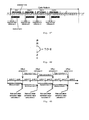
- Figure 52 shows a global structure of a protocol state diagram. From the SoftReset state, one of two distinct startup state machines is entered depending on how the configuration settings are chosen. For pure static or mixed static/dynamic configurations the fault-tolerant, distributed startup is triggered by the transition G1. For pure dynamic configurations it depends on whether a node is a master node or not, when deciding which transition (G2 or G3) the startup state machine has to take.
- State transitions marked with the suffix 'c' are aligned to cycle boundaries, state transitions tagged with an 'i' are executed immediately, i.e. as soon as the specific condition becomes true.
- the SoftReset state is part of the overall protocol state diagram and is not just a component of startup and reintegration.
- the host configures the communication controller while it is in SoftReset state. If the communication controller is in any other state, the host must force the communication controller to re-enter the SoftReset state in order to change it's configuration.
- a node may enter communication (i.e., the NormalStatic state) via the coldstart path ( ColdStartICW and ColdStartPCW state sequence) initiating the schedule synchronization, or via the integration path ( InitRate, InitSchedule , and IntagrationPCW state sequence) integrating into an existing communication schedule.
- the configuration parameter can only be set or cleared in the SoftReset state. The transmission of more than SYNC frame within one cycle has to be prevented by the communication controller.
- the initial synchronization of the periodic TDMA schedule must be coordinated among all connected communication nodes. Since all sync nodes are authorized to initiate the schedule synchronization, simultaneously started and conflicting attempts by different sync nodes must be resolved. Each node initially transmits a Collision Avoidance Symbol (CAS, see Section "Frame Validation”) specifically for this purpose, before initiating the periodic schedule.
- CAS Collision Avoidance Symbol
- This symbol represents a kind of arbiter, which is used to resolve initial collisions of nodes trying to set up the communication schedule at the same time.
- Non-sync nodes as well as sync nodes start passive integration as soon as they receive sync frames from which to derive the TDMA schedule information.
- the node has to adapt its own clock to the global clock (rate and offset) and has to make its cycle time consistent with the global schedule observable at the network. Afterwards, these settings are checked for consistency with all available network nodes. Only if these checks are passed, can the node leave the integration phase and actively participate in communication.
- the semantic information that can be derived from the received data stream varies with the protocol state of the node. Certain frame validation checks have to be passed by a received frame or symbol, in order to be an appropriate input for the related logic block.
- a sync node maintains two different timers, vdStartup and vdStartupNoise , which serve as listen-timeouts in order to leave the initial sensing phase ( ListenStatic state) with the intention to start up the communication.
- the node local listen-timeout vdStartup has the same length ( gdStartup ) for each node in the system, which is configured to send an initial CAS during startup (sync node).
- vdStartup limits the listen time that used by a node to determine if there is already communication between other nodes or at least one sync node actively requesting the integration of others. If communication channel activity is detected on one of the configured pChannels channels while the node is in the ListenStatic state, the listen-timeout vdStartup is restarted.
- Any signal edge detectable at the receiver i.e., a signal edge, which has passed the glitch filter
- channel activity Any signal edge detectable at the receiver (i.e., a signal edge, which has passed the glitch filter) is referenced to as "channel activity”.
- Figure 53 shows listen-timeouts vdStartup and vdStartupNoise .
- the time-out interval gdStartup is constrained by the following inequality.
- gdStartup is derived internally from the given configuration parameters gdCycle and gdMaxDrift .
- the upper boundary for the listen timeout vdStartupNoise is a multiple of gdStartup and is configurable using the parameter pdStartupNoise .
- the listen-timeout must cover the maximum accumulated drift over the free-running, unsynchronized period.
- the maximum allowable drift between any two clocks in the network is an important system parameter and known at design time. This 'worst case' period has to be covered by configuring gdMaxDrift (unit: macroticks) accordingly. Furthermore, the nominal time between two trigger events caused by regular communication pattern is always smaller than one communication cycle gdCycle.
- the 'listen-only' mode is configured by setting vListenOnly while in the SoftReset state. vListenOnly cannot be set after leaving the SoftReset state, but can be cleared at any time.
- listen-only mode the node is able to receive all frames after integration to the running communication; i.e. the node is fully synchronized and performs the clock synchronization in order to keep this status.
- normal operation mode NormalStatic state
- the node does not actively participate in communication, i.e. neither symbols nor frames are transmitted.
- This mode supports communication diagnosis ('monitoring') as well as dedicated wake-up strategies, which require host interaction ( vListenOnly subsequently cleared) in order to actively participate in communication after wake-up.
- the node can be prevented from initializing the TDMA communication schedule by setting vColdStartInhibit in the SoftReset state.
- vColdStartInhibit cannot be set after leaving the SoftReset state, but can be cleared at any time.
- vColdStartInhibit can be mapped to the gColdStartMax configuration parameter, which utilizes the zero value as to keep the node from starting the network on its own initiative (refer to the chapter "host interface"). It has to be checked whether the parameter gColdStartMax can be accessed during run time, i.e., after leaving SoftReset state, as this is required for the "coldstart inhibit" function.
- the node is not allowed to initialize the cluster communication after having checked on existing communication.
- the node is allowed to integrate to a running cluster or to acknowledge another node, which initially tries to start the cluster communication.
- vColdStartInhibit does not restrict the node's ability to receive frames or to transmit frames.
- Figure 54 shows a startup state diagram - FlexRay Mode with Static Segment Configured.
- All nodes enter the ListenStatic state after being released from the SoftReset state. In this state the communication controller is ready to attempt network startup or enter a running network.
- the ListenStatic state from SoftReset or re-entering from integration path ( InitRate , InitSchedule , and IntegrationPCW state sequence)
- sync nodes start their listen-timeout vdStartup and their listen-timeout with noise vdStartupNoise .
- Network activity on any of pChannels channels, which is different from a valid SYNCFrame StartupEven causes a restart of the listen-timeout vdStartup .
- the rate correction value When re-entering ListenStatic state from any state, the rate correction value has to be reinitialized with pMicroOverheadperCycleNom .
- sync nodes are allowed to enter the ColdStartICW state. These nodes leave ListenStatic when a listen-timeout or listen-timeout with noise occurs before receiving a valid SYNCFrame StartupEven .
- a sync node transmits the initial CAS and then cyclically transmits its configured sync to enable the startup of the entire network. If more than one sync node's listen-timeout or listen-timeout with noise expires before a valid SYNCFrame StartupEven is received, they all enter ColdStartICW . In ColdStartICW normal data frames (without sync bit set) are not transmitted.
- vColdStartCount is incremented by one.
- vColdStartCount is compared to the allowed maximum gColdStartMax.
- the node re-enters ListenStatic . This measure ensures that a node unable to receive a valid SYNCFrame StartupPCW from at least one of pChannels channels, i.e. a node with 'incoming link failure', stops transmission after a predefined interval of time and thereby enables other nodes to assume the responsibility for starting communication for the cluster.
- vColdStartCount is incremented by one.
- the node remains in ColdStartICW for a period determined by the initial check window ( gdInitialCheckwindow ).
- the timer vdInitialCheckWindow is started, when ColdStartICW is entered, and thus covers the initial slot used for CAS transmission as well as three complete communication cycles (refer to definition of gdInitialCheckWindow in Section TBD). Consequently, gdInitialCheckWindow determines the time a node stays in ColdStartICW before entering ColdStartPCW . In order to take all reception events into account, this window does not have any gap, i.e. it also includes the network idle time (compare with the definition for gdPlausibilityCheckWindow ! Due to the fact that the node is not capable to receive during its own transmissions, the network observation is suspended during them.
- PCW Plausibility Check Window
- the node continues transmitting its sync frame periodically.
- the node performs a plausibility check in order to assess the network image gained during a bounded receive period determined by the plausibility check window gdPlausibilityCheckWindow .
- the node After each observation phase ( gdPlausibilityCheckWindow ) the node evaluates the results. The node re-enters ListenStatic if an inconsistency is observed regarding the number of valid SYNC frames received, and the node's observation matches the minority. On the other hand, the node is allowed to enter NormalStatic if the plausibility check is passed ( vInalidSyncCount ⁇ vValidSyncCount; see also the conditions for counter increment below). Two event counters (vValidSyncCount and vInvalidSyncCount ) are administrated in order to support decision-making. In accordance with the receive window definition, a clear distinction between several possible cases can be made for each slot. These slot scenarios are judged and counters are incremented according to the following rules (where x stands for channel A or B and y stands for the respective other channel):
- the plausibility check is passed, if vValidSyncCount is greater than vInvalidSyncCount .
- the transition to NormalStatic is only permitted, if the check is passed with vValidSyncCount >1, since the node considers itself correct and has therefore initialized the counter accordingly. If the value of vValidSyncCount is still one, there has been no valid determination so far and the node remains in ColdStartPCW state for another cycle.
- vColdStartCount is incremented by one.
- vColdStartCount is compared to the allowed maximum gColdStartMax .
- the offset measurement phase is applied in accordance to the regular scheme, too. This means that for each cycle with an odd cycle counter value the related sync frames are used to determine next offset correction term.
- the node in ColdStartPCW state requires at least one additional matching pair of sync frames suitable for rate measurement (same frame identifier, consecutive occurrence in 'even/odd' cycle order), in order to fulfill one of the necessary prerequisites for entering NormalStatic. As long as the node does receive a response, it performs the clock correction based on one "pair of matching sync" frames, namely its own transmissions (the value 0 is assumed). As soon as another node is recognized that answers with two valid SYNCFrame StartupPCW transmissions in even/odd cycle order, the node in ColdStartPCW is acknowledged by at least one other sync node and vSyncPairs is set to true. With the beginning of each rate measurement phase in ColdStartPCW state, the variable vSyncPairs is reset to false.
- the quality of the resulting correction terms for clock synchronization is assessed.
- the node is only permitted to execute transition into NormalStatic state, if the correction terms for both, rate and offset are below the configured limit settings (
- vRefSync contains the identifier of the sync frame that was used to enter the integration path.
- the sync node corresponding to this reference frame is called the reference node.
- InitRate is used to derive an initial rate correction value in order to adjust the local macrotick timing to the timing given by the reference node. To accomplish this, the time between the initial occurrence of the reference frame and its next occurrence is measured and the difference from the nominal cycle length is applied as the rate correction term.
- the initial reception of the reference frame (which causes the state transition into InitRate ) starts a timer.
- This timer covers gdCycle running in local macroticks and according to this timer a receive window is opened.
- pdInitRateMEarly microticks before the timer expires the early receive window is opened and with the expiration of the timer, pdInitRateMLate is applied to form the late receive window.
- next reference frame would occur after gdCycle .
- the node runs with the corrected rate (direct application of the correction term).
- the reference frame used for initial rate correction (which causes the state transition into InitSchedule state) is also used to determine the nominal schedule position, using the received identifier fFrameID .
- the node sets its local cycle time accordingly, i.e. it synchronizes the micro- and macrotick counters to the SOF in the received sync frame.
- the cycle counter value fCycleCount of the received sync frame is extracted and used to initialize the local cycle.
- the node follows the local schedule until the end of the current cycle without transmitting actively. Any further reception is ignored and neither rate nor offset measurements are performed. At the end of the cycle, the transition is made from InitSchedule to IntegrationPCW .
- the node As long as the node stays in IntegrationPCW state, the node is not allowed to schedule transmissions.
- the node In IntegrationPCW the node tries to confirm the settings copied from the reference node with the overall network communication scheme. For this purpose the node performs a cycle-based plausibility check similar to the check defined for the ColdStartPCW state (see Section "ColdStartPCW State").
- the plausibility check is passed if vValidSyncCount is greater than vInvalidSyncCount . Transition into NormalStatic can only take place if the check has been passed, but there are additional checks to pass (see clock correction term assessment and next paragraphs, respectively) before a node is allowed to join communication with the transition into the NormalStatic state.
- the plausibility check always runs concurrently with these additional checks until the plausibility check itself fails or a state transition due to another condition is executed.
- a regular measurement phase for the next rate correction term is started.
- the definition of state transitions for the protocol state machine automatically keeps the required 'grid' (starting with a cycle with an even cycle counter value).
- all sync frames are registered and pair-wise (sync frames with same frame identifier) evaluated for clock synchronization.
- the offset measurement phase is applied in accordance to the regular scheme, too. This means that for each cycle with an odd cycle counter value the related sync frames are used to determine next offset correction term.
- An integrating sync node requires at least one matching pair of sync frames suitable for rate measurement (same frame identifier, consecutive occurrence in 'even/odd' order) in order to fulfill one of the necessary prerequisites to enter NormalStatic state. Using this pair of sync frames, the node can acknowledge an existing node in ColdStartPCW or simply integrate to a synchronized cluster. For sync nodes that do not operate in listen-only mode ( vListenOnly is false), vSyncPairs is set to true as soon as the first matching pair of sync frames is received. If a sync node is configured as a listen-only node ( vListenOnly is true), it has to fulfill the same condition as non-sync nodes. These nodes need to receive at least two matching pairs of sync frames suitable for rate measurement (same frame identifier, consecutive occurrence).
- vSyncPairs is set to true as soon as two matching sync frames are part of current rate measurement period.
- the quality of the resulting correction terms for clock synchronization must be acceptable.
- the node is only allowed to join active communication (transition into NormalStatic state), if the correction terms for both, rate and offset are below the configured limit settings (
- the correction value vOffsetCorrection may exceed the configured limit vOffsetCorrectionOut as long as
- the variable vOffsetOut is set to true ( vOffsetOut is initialized with its default value ( vOffsetOut is set to false), when IntegrationPCW is entered from InitSchedule ). This variable is always evaluated, if a new offset correction term should be checked against the configured limit settings. Thus, the described exception is only made once, i.e., when the first offset correction term is available.
- the message interface to the host is served and the error management is performed.
- a node In the PassiveStatic state a node does not transmit any of its configured frames. Nevertheless, the node does not stop all activities. It continues clock synchronization, the reception of messages and the full support of the host interface.
- the PassiveStatic state is used to support the 'listen only' protocol feature, where nodes are fully synchronized and receive all available frames (including receive buffer update), but do not transmit anything.
- This mode is indicated by vListenOnly , which can be set by the host in the SoftReset state only. As soon as the host clears vListenOnly NormalStatic state is entered at the beginning of the next cycle.
- Figure 55 shows a protocol state diagram - pure dynamic segment.
- a single node that has been configured as sync master (pMaster is set) sends the SOC. With the end of the transmission the timers (of the receiver unit) are started according to the definitions in the media access chapter and the node enters NormalMaster state.
- the node sends and receives messages in the NormslMaster state according to its configuration. Upon entering the NormalMaster state, i.e. after the transmission of the SOC, the startup phase is completed. The master node does not need any acknowledgement from other nodes.
- All slave nodes ( pMaster is false) wait in the ListenDynamic state for a valid SOC transmission. All connected channels are independently monitored. The transition into NormalSlave and therefore the synchronization of both channels to the master is done on reception of the first valid SOC. After initialization of the wait timers, both channels can operate asynchronously with respect to the required frame mini-slotting on each of the channels.
- Slave nodes synchronies to a valid SOC and transmit and receive messages in NormalSlave state according to their configuration.
- a node In PassiveDynamic a node does not transmit any of its configured frames. Still, the node does not stop all activities, but continues the synchronization to SOC (via ListenDynamic state) and the reception of messages.
- the PassiveDynamic state is used to support the 'listen only' protocol feature, where the node is fully synchronized and receives all available frames (including receive buffer update), but does not transmit anything.
- This mode is indicated by vListenOnly , which can be set by the host in the SoftReset state only. As soon as the host clears vListenOnly , NormalSlave state is entered with beginning of the next cycle.
- the protocol controller Since the protocol controller still performs the transition to ListenDynamic state with every communication cycle, it is still synchronized to the master node. Therefore, the node is allowed to directly re-enter NormalSlave from ListenDynamic (with the begin of next cycle), if the host sets vListenOnly to false.
- the node is allowed to proceed directly into normal operation ( ListenStatic state) after having performed the offset measurement, correction phase, and regular rate measurement phase the first time.
- Figure 56 shows a collision-free Startup.
- the scenario illustrated in Figure 56 depicts three nodes with two of them configured to initiate the startup actively (sync nodes A and B).
- Node C does is not configured to schedule any sync frames and therefore is not allowed to enter ColdStartICW .
- the first cycle counter value received by nodes B and C is in the sync frame sent by node A and it is even.
- Nodes B and C follow the current schedule until cycle end and then transition into the IntegrationPCW state. Still these nodes behave passively, i.e., they do not participate the communication schedule with their own frames. After one complete rate measurement period (2 cycles) and the corresponding offset measurement and correction phase (during the second cycle), the sync node B is allowed to enter normal operation. The plausibility checks evaluates in the IntegrationPCW state are passed because on the reception of the reference sync frame vValidSyncCount is incremented, while vInvalidSyncCount remains unchanged. Consequently, with the start of next cycle, node B enters NormalStatic and starts to transmit messages according to its configuration.
- the node that initially sent the CAS On reception of the sync frame pair sent by another node (node B), which is synchronized to its own, the node that initially sent the CAS (node A) then enters NormalStatic at the start of next communication cycle (after a whole rate measurement period has been concluded). In NormalStatic all configured frames are scheduled for transmission. As soon as the node that initially sent the CAS and one other node have entered the NormalStatic state, the startup phase is concluded.
- Node C enters NormalStatic in the same cycle as node A, as soon as it performs the regular rate measurement phase based on 2 (or more) pairs of corresponding sync frames ( vSyncPairs is true).
- Figure 57 shows a Startup with a collision on the CAS symbol.
- the scenario illustrated in Figure 57 depicts three nodes with all of them configured to initiate the startup actively (sync nodes).
- a collision during startup results when two sync nodes leave SoftReset state at the same, or nearly the same time.
- two nodes enter ColdStartICW simultaneously and send their initial CAS at the same, or nearly the same time. Both nodes are then prepared to send their first sync frame.
- node A On reception of this sync frame, the other node (node A), which currently resides in the ColdStartICW state, returns to ListenStatic and waits for the next valid SYNCFrame StartupEven .
- the figure depicts the case where a node A integrates in the sixth cycle after the cycle in which the collision occurred.
- non-sync nodes may detect activity but no valid CAS because of the collision, while others may detect a valid CAS (because the topology prevents collisions). For both cases the reaction is the same, since valid CAS symbols are treated like network activity that cannot be interpreted. The nodes remain in ListenStatic and wait for the occurrence of a valid SYNCFrame StartupEven .
- Figure 58 shows a Startup with a plausibility check in IntegrationPCW failed.
- node B and C start another integration attempt. Via the integration path, both nodes finally synchronize on timing of node A. Meanwhile, Node A remains in ColdStartPCW state for the entire period because it does not detect a valid response.
- the error severity level directly influences the protocol behavior as described in the table (CC, CC to API, Result, BG, Comment).
- the FlexRay error handling matches the overall protocol state machine (see Figure 59).
- the currently active severity level shall be taken into account at each protocol decision.
- Error Severity Levels Name Severity Level Behavior Normal S0 CC: full operation.
- CC to API no warning, no error flags active.
- Result Normal operation.
- BG remains synchronized Warning S1 CC: full operation.
- CC to API flag for detected error.
- Result Maintain normal operation, provide error indication to host.
- BG Remains synchronized. Comment: No immediate effect on protocol operation.
- the host is informed of the error condition Error S2 CC: reduced operation.
- CC to API flag for detected error.
- BG Remains synchronized. Comment: CC self rescue is allowed. The fault causing the error was non-fatal. The CC will not act as a coldstart node for the wake-up procedure.
- Fatal Error S3 CC Operation halted. All signals to the bus driver and bus guardian are placed in defined states. CC to API: flag for detected error. Interaction with host must still be possible. Result: The node stops transmitting and receiving frames.
- BG BG enters FailSilent state due to loss of ARM signal. The BG disables transmissions until reset by host. Comment: CC self rescue not allowed. The fault causing the error was fatal. A reset from the host is required to resume operation.
- Figure 59 shows the protocol (error) state machine. After startup a FlexRay CC starts operation in
- the protocol (error) state machine shall remain in the Normal Static, Listen Only, Normal Master or Normal Slave state as long as no errors are detected (remain in error severity S0) or if any detected errors have error severity S1 (see Table 16).
- the detection of any error with an error severity of S2 shall cause the protocol state machine to enter the Passive state where the CC is not allowed to send frames but where all protocol mechanisms (frame reception, clock synchronization, etc.) remain active.
- the detection of any error with an error severity of S3 shall cause the protocol state machine to enter the Error state, where no frame transmission is allowed and all protocol operation ceases.
- the CC can only return to normal operation after being reset by the host. (see Table 16).
- the protocol (error) state shall be Error while at least one S3 severity error is active, otherwise it shall be Passive while at least one S2 severity error is active, otherwise it shall be in Normal Static (Listen Only, Normal Master, Normal Slave).
- the error level of the communication controller shall be the error level of the most severe error that is currently active.
- Table 17 lists the error flags and error counters of the FlexRay protocol. The following sections provide detailed description of the various flags and counters. Error Flags and Error Counters Error Flags Abbreviation Channel Status and Error Vector CSEV Frame Status and Error Vector FSEV Error Counters Abbreviation Valid Sync Frame Counter VSFC Invalid Sync Frame ID Counter ISIC Invalid Sync Frame Cycle Counter ISCC Missing Rate Measurement Counter MRMC Missing Offset Measurement Counter MOMC Clock Correction Failed Counter CCFC
- a FlexRay Communications Controller shall provide two channel-specific Frame Status and Error Vectors (FSEV's) for each communication buffer.
- CC's that are only capable of single channel communication need only provide an FSEV the channel that it supports.
- a dual channel controller needs to provide two buffers to allow a host using a "select first" style buffer to understand the communication on the "non-selected" communication channel. If the buffer is operating in a channel-specific mode the information on the other channel is redundant.
- the FSEV allows the host to determine the status of communications associated with the buffer.
- Each vector consists of six bits that provide indications of various error or normal conditions that can occur during the reception of a frame. Table 18 lists the contents of the vectors.
- Table 19 gives the sets of checks that make up the various error conditions that are reported in the FSEV and CSEV.
- Each static FlexRay frame buffer has corresponding FSEV's.
- the FSEV is reset (all flags set to 0) during configuration (“Soft Reset” state) and is not updated before the CC is synchronized within other devices in the network (“Normal” protocol state).
- the FSEV is updated at the time a frame has been completely received. In case no frame is received, the FSEV is updated upon reaching the end of the slot.
- the Null Frame Detection condition has an error severity of S0. All of the other conditions reported in the FSEV have an error severity level of S1.
- a FlexRay Communication Controller shall provide a channel-specific Channel Status and Error Vector (CSEV) for each supported communication channel.
- CSEV Channel Status and Error Vector
- the CSEV reports the status of all frames received on the communication channel, even if the frames do not have an explicit receive buffer. This implies that a host can get information about errors that may have occurred on the channel in slots that have no associated Frame Status and Error Vector.
- Table 20 lists the contents of the CSEV.
- the data in the CSEV is available to the host via the Communication Host Interface (CHI).
- the flags in the CSEV may be reset by the host.
- the CSEV reports the aggregate status of all frames on the communication channel. More specifically, the bit corresponding to a particular condition will be set if any frame has experienced that condition since the CSEV has been reset by the host. Errors that occur more than once will not receive any special indication. The reception of a frame with no errors shall not clear the flags in the CSEV.
- the Null Frame condition has an error severity of S0. All of the other conditions reported in the CSEV have an error severity level of S1.
- the Valid Sync Frame Counter counts the number of correctly received sync frames in one communication cycle For the purposes of this counter, a sync frame that is received on both channels only counts as a single valid sync frame.
- the counter shall start at zero at the beginning of the communication cycle.
- the VSFC from the previous communication cycle shall be available to the host until the end of the current cycle, at which time it shall be replaced by the VSFC of the current cycle.
- An error of severity S1 shall be detected if the Valid Sync Frame Counter exceeds 16 at the end of the communication cycle.
- An error of severity S1 state shall also be detected if the Valid Sync Frame Counter is zero at the end of the communication cycle.
- ISIC Invalid Sync Frame ID Counter
- the Invalid Sync Frame ID Counter counts the number of sync frames which are received with a slot mismatch error.
- the counter shall start at zero at the beginning of the communication cycle.
- the ISIC from the previous communication cycle shall be available to the host until the end of the current cycle, at which time it shall be replaced by the ISIC of the current cycle.
- An error of severity S2 shall be detected if the Invalid Sync Frame ID Counter is greater than the Valid Sync Frame ID Counter at the end of the communication cycle. This condition indicates that the local CC disagrees with the majority of sync frame senders with respect to the current Slot ID.
- ISCC Invalid Sync Frame Cycle Counter
- the Invalid Sync Frame Cycle Counter counts the number of sync frames which are received with a cycle counter mismatch.
- the counter shall start at zero at the beginning of the communication cycle.
- the ISCC from the previous communication cycle shall be available to the host until the end of the current cycle, at which time it shall be replaced by the ISCC of the current cycle.
- An error of severity S2 shall be detected if the Invalid Sync Frame Cycle Counter is greater than the Valid Sync Frame Counter at the end of the communication cycle. This condition indicates that the local CC disagrees with the majority of sync frame senders with respect to the current cycle count.
- the Missing Rate Measurement Counter counts the number of consecutive even/odd cycle pairs for which it was not possible to compute a clock rate correction term. This counter shall be set to zero when the node begins normal operation. It shall be incremented by one if no rate correction term can be computed at the end of an odd communication cycle. This would occur if the node has not received any matching pairs of even/odd cycle sync frames with the same Frame ID. If a rate correction term can be computed the CC shall reset this counter to zero at the end of the odd communication cycle.
- An error of severity S1 shall be detected if the MRMC is greater than zero but less than the parameter gMaxWithoutRate .
- An error of severity S2 shall be detected if the MRMC is greater than or equal to gMaxWithoutRate .
- the Missing Offset Measurement Counter counts the number of consecutive even/odd cycle pairs for which it was not possible to compute a clock offset correction term. This counter shall be set to zero when the node begins normal operation. It shall be incremented by one if no offset correction term can be computed at the end of an odd communication cycle. This would occur if the node has not received any sync frames during an odd communication cycle. If an offset correction term can be computed the CC shall reset this counter to zero at the end of the odd communication cycle.
- An error of severity S1 shall be detected if the MOMC is greater than zero but less than the parameter gMaxWithoutoffset .
- An error of severity S2 shall be detected if the MOMC is greater than or equal to gMaxWithoutOffset .
- the Clock Correction Failed Counter is used to limit the number of cycles that a node that is currently experiencing a clock offset or rate correction failure can remain at an error severity level of S2 (which allows self recovery) before being forced to an error severity level of S3 (where recovery is only possible via host intervention).
- This counter shall be set to zero when a node begins normal operation. It shall be incremented by one at the end of any odd communication cycle where either the Offset Correction Failed or Rate Correction Failed errors are active (see Sections "Offset Correction Failed” and "Rate Correction Failed” below). It is assumed that the inability to compute a rate or offset correction term does not affect that term's Correction Failed status.
- the CCFC shall be reset to zero at the end of an odd communication cycle if neither the Offset Correction Failed nor the Rate Correction Failed errors are active.
- Error Handling Level An error of severity S3 shall be detected if the CCFC is greater than or equal to the parameter gMaxWithoutClockCorrection .
- the host At the end of an odd communication cycle if the clock synchronization mechanism calculates an offset correction term which is outside of the green region (refer to the Clock Synchronization chapter) the host shall be considered to have detected an Offset Correction Failed error.
- the Offset Correction Error shall remain active until the node computes an offset correction term that is in the green area, at which time the node shall consider the Offset Correction Failed error inactive. Note that this implies that the inability to compute an offset correction term does not change the Offset Correction Failed status. The status can only change if an offset correction term is actually computed.
- the host At the end of an odd communication cycle if the clock synchronization mechanism calculates a rate correction term which is outside of the green region (refer to the Clock Synchronization chapter) the host shall be considered to have detected a Rate Correction Failed error.
- the Rate Correction Error shall remain active until the node computes a rate correction term that is in the green area, at which time the node shall consider the Rate Correction Failed error inactive. Note that this implies that the inability to compute a rate correction term does not change the Rate Correction Failed status. The status can only change if a rate correction term is actually computed.
- This error is active if the end of a correct SOC occurs before gdCycleMin . This condition is reset after a cycle of duration greater than gdCycleMin is observed.
- the error has a severity level of S1.
- This error is active if the end of a valid SOC does not occur before gdCycleMax . This error condition is reset with the reception of the next valid SOC.
- This error has a severity level of S2.
- This error flag is set if
- This error has a severity level of S2. Reset to S0 as soon as the next SOC is received.
- ISV Interrupt Status Vector
- ISV Interrupt Enable Vector
- the FlexRay Communication Controller provides error status information to the host via an Interrupt Status Vector (ISV).
- ISV Interrupt Status Vector
- Each of the error detection mechanisms described above has an associated bit in the ISV. All of the individual flags of the Channel Status and Error Vector are mapped into the ISV, as well as all individual warning/error conditions described above. There is one additional bit in the ISV to signal a receive buffer error. The bits of the ISV are set to one if the condition described above becomes true.
- the FlexRay CC provides at least one interrupt line to the application.
- Each of the interrupt sources in the Interrupt Status Vector (ISV) shall be enabled separately by an Interrupt Status Enable Vector (ISEV) which is set by the host.
- ISV will be updated regardless of the contents of the ISEV.
- the ISEV simply enables the access of the interrupt source to the interrupt line.
- An additional Interrupt Enable Vector is used to set interrupt conditions for any of the Frame Status Error Vectors, which exist for each "mailbox/buffer" of a FlexRay CC.
- This Frame Status Interrupt Enable Vector (FSIEV) enables the interrupt signaling to the host according to the set bits within this enable register, e.g. only CRC errors of any mailbox/buffer cause an interrupt.
- the following table shows the Interrupt Status Enable Vector (ISEV) for the corresponding signals in ISV_0 to ISV_2: ISEV_0 7 6 5 4 3 2 1 0 ENABLE CRC ENABLE SLOT ENABLE COUNT ENABLE LENGTH ENABLE FSEV ENABLE SOC Early ENABLE SOC Lost ENABLE ILLPIF ISEV_1 15 14 13 12 11 10 9 8 ENABLE ENABLE ENABLE ENABLE ENABLE MRMC MOMC Offset Failed Rate Failed Max CCFC Max SYNC Zero SYNC ISEV_2 23 22 21 20 19 18 17 16 ENABLE Minority VSCC ENABLE Minority VSIC
- a logical ONE enables the error condition to be a source to trigger the interrupt line to the host.
- a logical ZERO disables the signaling of that error condition to the host.
- the ISV will always represent the current status regardless of the value in the ISEV.
- FSIEV Frame Status Interrupt Enable Vector
- a logical ONE enables the signal to be a source to trigger the interrupt line to the host.
- a logical ZERO disables the signaling to the host.
- the FSEV will always represent the current status of the buffer regardless of the value in the FSIEV.
- SSV Startup Status Vector
- SSIEV Startup Status Interrupt Enable Vector
- Each of the interrupt sources in the Startup Status Vector shall be enabled separately by Startup Status Interrupt Enable Vector which is set by the application.
- the SSV will be updated regardless of the values of the SSIEV.
- the SSIEV enables the access of the interrupt source to the interrupt line.
- the following signals (error conditions) out of startup shall be summarized in SSV.
- the following table shows the Startup Status Interrupt Enable Vector for the corresponding startup status vector.
- SSVE 7 6 5 4 3 2 1 0 ENABLE coldst art max ENABLE Plaus ENABLE prefsync ENABLE coldst art path ENABLE pstart upnoise
- the current error severity level (S0 through S3) shall be made available to the host.
- the CHI is the interface between the higher layers and the data link layer.
- CHI CHI suggests that a FlexRay node consists always of two primary hardware elements, which are connected via the CHI:
- CHI is above the data link layer.
- a transport layer or a fault tolerant communication layer (FTCom) would be above the CHI.
- FCom fault tolerant communication layer
- the layers above the CHI dictate what mechanisms the CHI must contain. To adequately support the layers above it, the CHI must provide mechanisms that:
- the CHI shall be implemented as a 16 bit aligned address/data bus to support Motorola's PPC and Star12 micro controllers, and Texas Instruments' TMS470 family.
- Designated configuration data should be protected from unintended manipulation by the host, by allowing changes only in a specific Communication Controller mode (e.g. soft reset state).
- a specific Communication Controller mode e.g. soft reset state
- a FIFO message area should be provided for receiving frames that do not have a dedicated receive buffer. It should support a maskable rejection filter with the following characteristics:
- All information contained in a valid received frame should be stored in the designated receive buffer (or FIFO) except the frame CRC.
- the receive buffer should contain a field indicating the channel on which the stored frame was received. If the header of the received frame does not match any of the configured filters, the frame should be discarded without storing any frame data.
- the buffer contents prior to the reception should not be deleted or overwritten. If a null frame is received in a slot, the buffer contents prior to the reception should be overwritten if so configured. The discrepancy to the configured frame should be signaled to the host using a suitable bit in the corresponding buffer status register.
- the status and error registers should keep their data unchanged until the soft reset is released.
- This section enumerates the registers supported by the Communication Controller to provide the host with status information regarding the operation of the controller.
- Error Handling Level is a characteristic of the V5 Error Management strategy and may not apply if the V5 only Error Management strategy is not retained in V6.
- the CC shall provide a Startup Status Vector with following status flags:
- This section enumerates the registers supported by the Communication Controller(CC) to allow the host to control the operation of the CC.
- the clock prescaler register may be modified only in soft reset. It consists of the following three fields:
- microtick duration which is provided to the bus guardian.
- the CC shall provide two Timer Interrupt Configuration Registers for configurable timer interrupts. Each shall contain three fields:
- the maximum cycle counter value must be one less than a power of two.
- a configuration switch decides whether the transmitter may add missing data bytes if the configured frame data length exceeds the length of the buffer data field.
- This configuration switch determines whether the data is copied out of a received Null Frame into the mailbox buffer or not. The configuration switch applies to all mailbox receive buffers of the CC.
- the value in this register determines the maximum number of cycles a cold starting node is permitted to try to start up the network without receiving any valid response from another node. If the value is '0' the CC is not allowed to start up the communication.
- the CC shall provide a Startup Status Interrupt Enable Vector for Enabling (logical '1') or Disabling (logical '0') interrupts corresponding to the following events:
- the host access to the mailbox message buffers is controlled by the use of a Buffer Control Register.
- This control register has one byte for each mailbox buffer.
- IFLG is set by the CC after transmission has been completed and the host may access the buffer for writing next message.
- the communication controller has to provide 32 configurable mailbox message buffers for data communication with a frame length of up to 32 data bytes. (Values are valid for FPGA V5.)
- the mailbox buffers can be configured to be used as transmit, dedicated receive or FIFO receive buffers.
- Each buffer has to include the complete frame header and data field, and shall not include the frame CRC.
- the CC must provide suitable mechanisms to grant a secure access to the DPRAM buffers. Using e.g. a locking mechanism, either the CC or the host may get access to one particular mailbox buffer. In order to prevent data mismatch a window access scheme may be used (e.g. one window for the active transmit buffer, one for the active dedicated receive buffer, and one for the active FIFO receive buffer). Only one single buffer of one type may be locked and visible to the host at the same time.
- mailboxes which can be configured during Soft Reset only while the others can be reconfigured during runtime.
- a portion of message buffers can be configured as transmit buffers.
- the set of transmit buffers shall be contiguous in the register map starting at buffer 32 (for FPGA V5) and ending before the first receive buffer.
- the first matching buffer will be sent out by the CC.
- reconfigurable mailboxes For transmit frames in the dynamic part reconfigurable mailboxes can be used.
- the frame ID and the corresponding DLC can be reconfigured during runtime (FPGA V5 and V6).
- the CC does not calculate the transmit header CRC (FPGA V5 and V6). It must be provided by the host for all transmitted frames.
- the length field in all messages (static and dynamic) reflects the actual physical frame data length as defined in the frame format.
- the CC may use mailbox transmit buffer structures shorter than the actual (physical) data frame length in the static segment. In this case, the CC will generate padding bytes to ensure that frames have proper physical length. However, this capability must be enabled via configuration (see Section "Transmitter Generated Padding").
- the padding pattern shall be logical ZERO.
- the padding function shall apply only to frames to be transmitted in the static part. In the dynamic part no frame will be transmitted if the data field in the buffer is shorter than the configured data length.
- the frame will be transmitted containing the current buffer contents consisting of the previously transmitted data.
- the CC will set the Null Frame Bit in the frame header to indicate that the transmitted message is a Null Frame. (For FPGA V5 this indication will be one single bit). Null Frames are not transmitted in the dynamic part.
- a portion of the CC's message buffers can be configured as dedicated receive buffers.
- the set of dedicated receive buffers shall be contiguous in the register map starting after the last transmit buffer and ending before the first FIFO receive buffer.
- the CC transfers valid received messages from the serial receive message buffer to the dedicated receive buffer with the matching filter configuration.
- a portion of the CC's message buffers can be configured as FIFO receive buffers.
- the set of FIFO receive buffers shall be contiguous in the register map starting after the last dedicated receive buffer and ending with the last message buffer.
- the CC transfers valid received messages from the serial receive message buffer to the FIFO receive buffer if there is no matching dedicated receive buffer and the header is not rejected by the FIFO Rejection filter (see Section "FIFO Filtering").
- each message buffer must possess a Frame Status and Error Vector.
- the Frame Status and Error Vector contains six bits which are summarized in the following table: Frame Status and Error Vector Status/Error Flag Bits Tx Buffer Rx Buffer FIFO Buffer Null Frame 1 Null Frame transmitted Null Frame received (static part) Null Frame received Empty Slot 1 - No bus traffic detected (static part) - Bit Coding/CRC Error 1 - Error detected (bit coding, header or frame CRC, in static part) - Length Mismatch 1 - Length Mismatch detected (static part) - Slot Mismatch 1 - Slot Mismatch detected - Cycle Counter Mismatch 1 - Cycle Counter Mismatch detected (static part) -
- the vector content is updated at the end of the slot (defined by the configured Frame ID) by the communication controller and can be checked by the host.
- searching commences with the receive buffer adjacent to the last transmit buffer. It proceeds incrementally through the remaining receive buffers. If more than one receive buffer holds the same frame ID, the error vector is updated in the first matching buffer.
- the flags are set if one of the listed errors is detected by the communication controller.
- the host can check the vector any time. An interrupt will be triggered by the CC if the corresponding interrupt enable bit in the General Enable Register is set (see below).
- Message filtering is done by checking specific fields in a message against corresponding configuration constants in the buffer, with the stipulation that message is only processed further if the required matches occur. Otherwise, it is discarded. Messages are filtered on the following message fields:
- Masking of message filters means that some (parts) of the filtering parameters may be configured to be disregarded (set to "don't care”).
- Channel Filtering field (2 bits) associated with each buffer. It serves as a filter for a receive message buffer, and as a control field for a transmit message buffer.
- Every Transmit and Receive mailbox message buffer contains a frame ID. This frame ID is used differently for receive and transmit message buffers
- Cycle Counter Filtering is based on the notion of a Cycle Set. For filtering purposes, a match occurs if any one of the elements of the set is matched.
- the operation of the filtering mechanism depends on the configuration of the buffer:
- Message ID filtering applies only for receive message buffers. For message ID filtering the first two data bytes out of the receive buffer are used. The received frame will be stored in the configured receive buffer if the message ID, channel and cycle counter match. The frame ID will be stored in the buffer, but ignored for filtering.
- Each register consists of 36 bits for channel (2 bits), frame ID (12 bits), cycle counter (6 bits), and message ID (16 bits). The two registers can be reconfigured in soft reset as well as during runtime.
- a received frame will be stored in the next free FIFO buffer if the channel, frame ID, cycle counter, and message ID are not rejected by the configured reject and mask reject filter and if there is no matching dedicated receive buffer in the mailbox.
- interrupts provide a close link to the protocol timing as they are triggered almost immediately when an error is detected by the controller, a frame is received or transmitted, or a configured timer interrupt is activated. This allows the host to react very quickly on specific error conditions, timers and events. On the other hand too many interrupts can cause the host to miss deadlines required for the application. Therefore it must be possible to disable/enable interrupts, separately and as a whole.
- An interrupt may be triggered when
- Tracking status and generating interrupts when a status change occurs are two independent tasks. Regardless of whether an interrupt is enabled, or not, the corresponding status should be tracked
- At least one hardware interrupt line shall be available to signal an interrupt to the host.
- the communication controller has to provide a General Interrupt and Error Indication Register.
- General Interrupt Register General Interrupt Flag Bits Channel Receiver Channel Bit Coding/CRC Error 1 Error detected (bit coding, header or frame CRC))
- a Slot Mismatch 1 Slot Mismatch detected A Cycle Counter Mismatch 1 Cycle Counter Mismatch detected
- a Length Mismatch 1 Length Mismatch detected A SOC Normal / Collision Avoidance symbol 1 SOC Normal or Collision Avoidance symbol detected
- a SOC Too Early 1 SOC received before qdCycleMin A SOC Lost 1 SOC not received before gdCycleMax
- Bit Coding/CRC Error 1 Error detected (bit coding, header or frame CRC)
- B Slot Mismatch 1 Slot Mismatch detected B Cycle Counter Mismatch 1 Cycle Counter Mismatch detected
- B Length Mismatch 1 Length Mismatch detected B SOC Normal / Collision Avoidance symbol 1 SOC Normal symbol detected B S
- the flags are set when the communication controller detects one of the listed errors or SOC symbols.
- the host can check the vector.
- the communication controller has to provide a General Error Interrupt, which will be triggered when any of the flags is set, provided the corresponding interrupt is enabled.
- the CC has to provide for each general interrupt indication flag a General Interrupt Enable flag.
Landscapes
- Engineering & Computer Science (AREA)
- Computer Networks & Wireless Communication (AREA)
- Signal Processing (AREA)
- Physics & Mathematics (AREA)
- Probability & Statistics with Applications (AREA)
- Theoretical Computer Science (AREA)
- Small-Scale Networks (AREA)
Priority Applications (17)
| Application Number | Priority Date | Filing Date | Title |
|---|---|---|---|
| EP02008171A EP1355456A1 (en) | 2002-04-16 | 2002-04-16 | FlexRay communication protocol |
| AT03008737T ATE305197T1 (de) | 2002-04-16 | 2003-04-16 | Verfahren zur datenübertragung in einem kommunikationssystem |
| EP03008740A EP1355460B1 (en) | 2002-04-16 | 2003-04-16 | Method for monitoring a communication media access schedule of a communication controller of a communication system |
| DE60302697T DE60302697T2 (de) | 2002-04-16 | 2003-04-16 | Verfahren zum Synchronisieren von Uhren in einem verteilten Kommunikationssystem |
| EP03008739A EP1355459B1 (en) | 2002-04-16 | 2003-04-16 | Method for synchronizing clocks in a distributed communication system |
| EP03008741A EP1355461B1 (en) | 2002-04-16 | 2003-04-16 | Method and unit for bit stream decoding |
| DE60301752T DE60301752T9 (de) | 2002-04-16 | 2003-04-16 | Verfahren zur Überwachung einer Zugriffsablaufsteuerung für ein Kommunikationsmedium einer Kommunikationssteuerung eines Kommunikationssystems |
| DE60301637T DE60301637T2 (de) | 2002-04-16 | 2003-04-16 | Verfahren zur Datenübertragung in einem Kommunikationssystem |
| DE60314935T DE60314935T2 (de) | 2002-04-16 | 2003-04-16 | Verfahren und Einheit zur Bitstromdekodierung |
| AT03008741T ATE367700T1 (de) | 2002-04-16 | 2003-04-16 | Verfahren und einheit zur bitstromdekodierung |
| AT03008739T ATE313195T1 (de) | 2002-04-16 | 2003-04-16 | Verfahren zum synchronisieren von uhren in einem verteilten kommunikationssystem |
| AT03008740T ATE306163T1 (de) | 2002-04-16 | 2003-04-16 | Verfahren zur überwachung einer zugriffsablaufsteuerung für ein kommunikationsmedium einer kommunikationssteuerung eines kommunikationssystems |
| EP03008737A EP1355458B1 (en) | 2002-04-16 | 2003-04-16 | Method for transmitting data within a communication system |
| US10/613,027 US7586953B2 (en) | 2002-04-16 | 2003-07-07 | Method for monitoring a communication media access schedule of a communication controller of a communication system |
| US10/613,039 US7430261B2 (en) | 2002-04-16 | 2003-07-07 | Method and bit stream decoding unit using majority voting |
| US10/613,088 US20040081193A1 (en) | 2002-04-16 | 2003-07-07 | Method for transmitting data within a communication system |
| US10/613,000 US20050141565A1 (en) | 2002-04-16 | 2003-07-07 | Method for synchronizing clocks in a distributed communication system |
Applications Claiming Priority (1)
| Application Number | Priority Date | Filing Date | Title |
|---|---|---|---|
| EP02008171A EP1355456A1 (en) | 2002-04-16 | 2002-04-16 | FlexRay communication protocol |
Publications (1)
| Publication Number | Publication Date |
|---|---|
| EP1355456A1 true EP1355456A1 (en) | 2003-10-22 |
Family
ID=28459462
Family Applications (1)
| Application Number | Title | Priority Date | Filing Date |
|---|---|---|---|
| EP02008171A Withdrawn EP1355456A1 (en) | 2002-04-16 | 2002-04-16 | FlexRay communication protocol |
Country Status (1)
| Country | Link |
|---|---|
| EP (1) | EP1355456A1 (fi) |
Cited By (29)
| Publication number | Priority date | Publication date | Assignee | Title |
|---|---|---|---|---|
| WO2004051925A3 (en) * | 2002-12-03 | 2004-08-05 | Motorola Inc | System node and method for providing media arbitration in a time-slotted system |
| DE102004009468A1 (de) * | 2004-02-27 | 2005-09-15 | Daimlerchrysler Ag | Verfahren und Einrichtung zur Übertragung serieller Bitströme |
| EP1585266A3 (de) * | 2004-03-24 | 2005-11-02 | Bosch Rexroth AG | Verfahren zur Datenübertragung |
| WO2005119951A1 (de) * | 2004-06-04 | 2005-12-15 | Robert Bosch Gmbh | Verfahren zur etablierung einer globalen zeitbasis in einem zeitgesteuerten kommunikationssystem und kommunikationssystem |
| WO2006067673A3 (en) * | 2004-12-20 | 2006-11-02 | Philips Intellectual Property | Bus guardian as well as method for monitoring communication between and among a number of nodes, node comprising such bus guardian, and distributed communication system comprising such nodes |
| WO2006129269A3 (en) * | 2005-06-02 | 2007-02-22 | Philips Intellectual Property | Method to synchronize locally provided clocks of different communication nodes of a time-triggered communication system |
| WO2007128347A1 (en) | 2006-05-09 | 2007-11-15 | Freescale Semiconductor, Inc. | Data communication unit, integrated circuit and method for buffering data |
| WO2008052849A1 (de) | 2006-10-31 | 2008-05-08 | Robert Bosch Gmbh | Verfahren zum senden eines datenübertragungsblocks und verfahren und system zum übertragen eines datenübertragungsblocks |
| WO2008052850A3 (de) * | 2006-11-03 | 2008-10-16 | Bosch Gmbh Robert | Verfahren und system zur übertragung von datenrahmen |
| RU2380841C2 (ru) * | 2004-08-05 | 2010-01-27 | Роберт Бош Гмбх | КОММУНИКАЦИОННЫЙ МОДУЛЬ ДЛЯ СЕТИ FlexRay |
| US7983250B2 (en) | 2004-02-24 | 2011-07-19 | Robert Bosch Gmbh | Method and communications system for transmitting information in a motor vehicle |
| US8095740B2 (en) * | 2004-08-05 | 2012-01-10 | Robert Bosch Gmbh | Method and apparatus for accessing data of a message memory of a communication module |
| EP1886214A4 (en) * | 2005-05-10 | 2012-08-22 | Continental Automotive Systems | NETWORK OF VEHICLES HAVING TEMPORAL CRANE ACCESSES AND METHOD THEREOF |
| US20120224591A1 (en) * | 2009-10-27 | 2012-09-06 | Hitachi Automotive Systems, Ltd. | Vehicle-Mounted Network Device |
| US8484383B2 (en) * | 2004-08-05 | 2013-07-09 | Robert Bosch Gmbh | FlexRay communication controller |
| CN103281321A (zh) * | 2013-05-24 | 2013-09-04 | 航天东方红卫星有限公司 | 一种星载FlexRay总线动态段通信方法 |
| EP2053830A3 (en) * | 2007-08-28 | 2013-11-06 | Honeywell International Inc. | Autocratic low complexity gateway/guardian strategy and/or simple local guardian strategy for flexray or other distributed time-triggered protocol |
| EP2509263A4 (en) * | 2009-12-02 | 2014-01-15 | Toyota Motor Co Ltd | DATA COMMUNICATION NETWORK SYSTEM |
| US8660131B2 (en) | 2005-06-09 | 2014-02-25 | Nxp B.V. | Storage unit for communication system node, method for data storage and communication system node |
| US9825775B2 (en) | 2014-12-16 | 2017-11-21 | Hyundai Motor Company | Local interconnect network system and method, and computer readable medium for implementing the method |
| CN109547260A (zh) * | 2018-12-07 | 2019-03-29 | 中国航空工业集团公司西安航空计算技术研究所 | 一种FlexRay网络配置方法及系统 |
| CN110311752A (zh) * | 2019-06-14 | 2019-10-08 | 杭州爱科科技股份有限公司 | 用于芯片间快速快稳定的通信方法及其通信装置 |
| CN111565378A (zh) * | 2019-02-14 | 2020-08-21 | 深圳长城开发科技股份有限公司 | LoRa通信方法以及LoRa通信系统 |
| CN111682987A (zh) * | 2020-06-09 | 2020-09-18 | 联合汽车电子(重庆)有限公司 | 基于osek nm的实车环境模拟及快速测试系统 |
| WO2020200996A1 (de) * | 2019-04-02 | 2020-10-08 | Knorr-Bremse Systeme für Nutzfahrzeuge GmbH | System zur datenübertragung für ein nutzfahrzeug sowie verfahren hierzu |
| US11188400B2 (en) | 2002-12-17 | 2021-11-30 | Stragent, Llc | System, method and computer program product for sharing information in a distributed framework |
| CN113946535A (zh) * | 2021-10-29 | 2022-01-18 | 西安微电子技术研究所 | 一种总线的宏节拍和周期生成方法 |
| KR20220083329A (ko) * | 2020-12-11 | 2022-06-20 | 한림대학교 산학협력단 | 슬롯 카운터 파라미터를 이용한 프레임 처리량 산출 시스템, 방법 및 프로그램 |
| EP4236214A1 (en) * | 2022-02-23 | 2023-08-30 | Nxp B.V. | Controller area network transceiver and method for the transceiver |
Citations (1)
| Publication number | Priority date | Publication date | Assignee | Title |
|---|---|---|---|---|
| US4161786A (en) * | 1978-02-27 | 1979-07-17 | The Mitre Corporation | Digital bus communications system |
-
2002
- 2002-04-16 EP EP02008171A patent/EP1355456A1/en not_active Withdrawn
Patent Citations (1)
| Publication number | Priority date | Publication date | Assignee | Title |
|---|---|---|---|---|
| US4161786A (en) * | 1978-02-27 | 1979-07-17 | The Mitre Corporation | Digital bus communications system |
Cited By (47)
| Publication number | Priority date | Publication date | Assignee | Title |
|---|---|---|---|---|
| WO2004051925A3 (en) * | 2002-12-03 | 2004-08-05 | Motorola Inc | System node and method for providing media arbitration in a time-slotted system |
| US8085700B2 (en) | 2002-12-03 | 2011-12-27 | Freescale Semiconductor, Inc. | System node and method for providing media arbitration |
| US11354179B2 (en) | 2002-12-17 | 2022-06-07 | Stragent, Llc | System, method and computer program product for sharing information in a distributed framework |
| US11188400B2 (en) | 2002-12-17 | 2021-11-30 | Stragent, Llc | System, method and computer program product for sharing information in a distributed framework |
| US7983250B2 (en) | 2004-02-24 | 2011-07-19 | Robert Bosch Gmbh | Method and communications system for transmitting information in a motor vehicle |
| DE102004009468A1 (de) * | 2004-02-27 | 2005-09-15 | Daimlerchrysler Ag | Verfahren und Einrichtung zur Übertragung serieller Bitströme |
| EP1585266A3 (de) * | 2004-03-24 | 2005-11-02 | Bosch Rexroth AG | Verfahren zur Datenübertragung |
| US7920587B2 (en) | 2004-06-04 | 2011-04-05 | Robert Bosch Gmbh | Method for establishing a global time base in a time-controlled communications system and communications system |
| WO2005119951A1 (de) * | 2004-06-04 | 2005-12-15 | Robert Bosch Gmbh | Verfahren zur etablierung einer globalen zeitbasis in einem zeitgesteuerten kommunikationssystem und kommunikationssystem |
| CN1965514B (zh) * | 2004-06-04 | 2012-05-02 | 罗伯特·博世有限公司 | 在时间控制的通信系统中建立全球时基的方法和通信系统 |
| US8484383B2 (en) * | 2004-08-05 | 2013-07-09 | Robert Bosch Gmbh | FlexRay communication controller |
| US7769906B2 (en) | 2004-08-05 | 2010-08-03 | Robert Bosch Gmbh | FlexRay communication module |
| RU2380841C2 (ru) * | 2004-08-05 | 2010-01-27 | Роберт Бош Гмбх | КОММУНИКАЦИОННЫЙ МОДУЛЬ ДЛЯ СЕТИ FlexRay |
| US8095740B2 (en) * | 2004-08-05 | 2012-01-10 | Robert Bosch Gmbh | Method and apparatus for accessing data of a message memory of a communication module |
| WO2006067673A3 (en) * | 2004-12-20 | 2006-11-02 | Philips Intellectual Property | Bus guardian as well as method for monitoring communication between and among a number of nodes, node comprising such bus guardian, and distributed communication system comprising such nodes |
| US8228953B2 (en) * | 2004-12-20 | 2012-07-24 | Nxp B.V. | Bus guardian as well as method for monitoring communication between and among a number of nodes, node comprising such bus guardian, and distributed communication system comprising such nodes |
| EP1886214A4 (en) * | 2005-05-10 | 2012-08-22 | Continental Automotive Systems | NETWORK OF VEHICLES HAVING TEMPORAL CRANE ACCESSES AND METHOD THEREOF |
| WO2006129269A3 (en) * | 2005-06-02 | 2007-02-22 | Philips Intellectual Property | Method to synchronize locally provided clocks of different communication nodes of a time-triggered communication system |
| US8660131B2 (en) | 2005-06-09 | 2014-02-25 | Nxp B.V. | Storage unit for communication system node, method for data storage and communication system node |
| WO2007128347A1 (en) | 2006-05-09 | 2007-11-15 | Freescale Semiconductor, Inc. | Data communication unit, integrated circuit and method for buffering data |
| US20100293443A1 (en) * | 2006-10-31 | 2010-11-18 | Josef Newald | Method for transmitting a data transfer block and method and system for transferring a data transfer block |
| WO2008052849A1 (de) | 2006-10-31 | 2008-05-08 | Robert Bosch Gmbh | Verfahren zum senden eines datenübertragungsblocks und verfahren und system zum übertragen eines datenübertragungsblocks |
| US8413017B2 (en) | 2006-10-31 | 2013-04-02 | Robert Bosch Gmbh | Method for transmitting a data transfer block and method and system for transferring a data transfer block |
| CN101589554B (zh) * | 2006-11-03 | 2013-10-30 | 罗伯特.博世有限公司 | 传输数据帧的方法和系统 |
| WO2008052850A3 (de) * | 2006-11-03 | 2008-10-16 | Bosch Gmbh Robert | Verfahren und system zur übertragung von datenrahmen |
| EP2053830A3 (en) * | 2007-08-28 | 2013-11-06 | Honeywell International Inc. | Autocratic low complexity gateway/guardian strategy and/or simple local guardian strategy for flexray or other distributed time-triggered protocol |
| US20120224591A1 (en) * | 2009-10-27 | 2012-09-06 | Hitachi Automotive Systems, Ltd. | Vehicle-Mounted Network Device |
| EP2495914A4 (en) * | 2009-10-27 | 2014-07-30 | Hitachi Automotive Systems Ltd | VEHICLE-ASSEMBLED NETWORK DEVICE |
| EP2509263A4 (en) * | 2009-12-02 | 2014-01-15 | Toyota Motor Co Ltd | DATA COMMUNICATION NETWORK SYSTEM |
| US8660149B2 (en) | 2009-12-02 | 2014-02-25 | Toyota Jidosha Kabushiki Kaisha | Data communication network system |
| CN103281321A (zh) * | 2013-05-24 | 2013-09-04 | 航天东方红卫星有限公司 | 一种星载FlexRay总线动态段通信方法 |
| CN103281321B (zh) * | 2013-05-24 | 2016-02-10 | 航天东方红卫星有限公司 | 一种星载FlexRay总线动态段通信方法 |
| US9825775B2 (en) | 2014-12-16 | 2017-11-21 | Hyundai Motor Company | Local interconnect network system and method, and computer readable medium for implementing the method |
| CN109547260A (zh) * | 2018-12-07 | 2019-03-29 | 中国航空工业集团公司西安航空计算技术研究所 | 一种FlexRay网络配置方法及系统 |
| CN111565378B (zh) * | 2019-02-14 | 2024-04-19 | 深圳长城开发科技股份有限公司 | LoRa通信方法以及LoRa通信系统 |
| CN111565378A (zh) * | 2019-02-14 | 2020-08-21 | 深圳长城开发科技股份有限公司 | LoRa通信方法以及LoRa通信系统 |
| WO2020200996A1 (de) * | 2019-04-02 | 2020-10-08 | Knorr-Bremse Systeme für Nutzfahrzeuge GmbH | System zur datenübertragung für ein nutzfahrzeug sowie verfahren hierzu |
| CN110311752B (zh) * | 2019-06-14 | 2022-04-08 | 杭州爱科科技股份有限公司 | 用于芯片间快速快稳定的通信方法及其通信装置 |
| CN110311752A (zh) * | 2019-06-14 | 2019-10-08 | 杭州爱科科技股份有限公司 | 用于芯片间快速快稳定的通信方法及其通信装置 |
| CN111682987B (zh) * | 2020-06-09 | 2021-09-14 | 联合汽车电子(重庆)有限公司 | 基于osek nm的实车环境模拟及快速测试系统 |
| CN111682987A (zh) * | 2020-06-09 | 2020-09-18 | 联合汽车电子(重庆)有限公司 | 基于osek nm的实车环境模拟及快速测试系统 |
| KR20220083329A (ko) * | 2020-12-11 | 2022-06-20 | 한림대학교 산학협력단 | 슬롯 카운터 파라미터를 이용한 프레임 처리량 산출 시스템, 방법 및 프로그램 |
| KR102499337B1 (ko) | 2020-12-11 | 2023-02-10 | 한림대학교 산학협력단 | 슬롯 카운터 파라미터를 이용한 프레임 처리량 산출 시스템, 방법 및 프로그램 |
| CN113946535A (zh) * | 2021-10-29 | 2022-01-18 | 西安微电子技术研究所 | 一种总线的宏节拍和周期生成方法 |
| CN113946535B (zh) * | 2021-10-29 | 2023-09-19 | 西安微电子技术研究所 | 一种总线的宏节拍和周期生成方法 |
| EP4236214A1 (en) * | 2022-02-23 | 2023-08-30 | Nxp B.V. | Controller area network transceiver and method for the transceiver |
| US12212430B2 (en) | 2022-02-23 | 2025-01-28 | Nxp B.V. | Controller area network transceiver and method for the transceiver |
Similar Documents
| Publication | Publication Date | Title |
|---|---|---|
| EP1355456A1 (en) | FlexRay communication protocol | |
| EP1355460B1 (en) | Method for monitoring a communication media access schedule of a communication controller of a communication system | |
| DE60301767T2 (de) | Normalisierung eines Verifizierungsmasses in einer Vorrichtung zur Sprecherverifikation | |
| US7549072B2 (en) | Method and device for synchronizing the global time of a plurality of buses and a corresponding bus system | |
| US7920587B2 (en) | Method for establishing a global time base in a time-controlled communications system and communications system | |
| EP1624620A1 (en) | FlexRay communication controller | |
| CN106444425B (zh) | 面向航空发动机分布式控制的ttp/c总线控制器设计方法 | |
| WO2007054877A1 (en) | Bus guardian with improved channel monitoring | |
| JP2010521858A (ja) | 分散通信システムのノード、分散通信システムに結合されたノード及び監視装置 | |
| US8228953B2 (en) | Bus guardian as well as method for monitoring communication between and among a number of nodes, node comprising such bus guardian, and distributed communication system comprising such nodes | |
| Pimentel et al. | Dependable automotive CAN networks | |
| Specification | Bosch | |
| Schätz et al. | FlexRay protocol | |
| Shaheen et al. | A comparison of emerging time-triggered protocols for automotive X-by-wire control networks | |
| Srinivasan et al. | Real-time architecture analysis: A COTS perspective | |
| Kammerer | TTCAN | |
| Navet et al. | Fault tolerant services for safe in-car embedded systems | |
| El Salloum et al. | FlexRay | |
| Bertoluzzo et al. | Application protocols for safety-critical CAN-networked systems | |
| Paulitsch | Roman Obermaisser | |
| Mahmud | Various Emerging Time-Triggered Protocols for Drive-by-Wire Applications | |
| Cena et al. | Protocols and Services in Controller Area Networks | |
| predictable as Time | TTP | |
| Wang et al. | Enforcing Fail-Silence in the Entire FlexRay Communication Cycle |
Legal Events
| Date | Code | Title | Description |
|---|---|---|---|
| PUAI | Public reference made under article 153(3) epc to a published international application that has entered the european phase |
Free format text: ORIGINAL CODE: 0009012 |
|
| AK | Designated contracting states |
Kind code of ref document: A1 Designated state(s): AT BE CH CY DE DK ES FI FR GB GR IE IT LI LU MC NL PT SE TR |
|
| AX | Request for extension of the european patent |
Extension state: AL LT LV MK RO SI |
|
| AKX | Designation fees paid | ||
| REG | Reference to a national code |
Ref country code: DE Ref legal event code: 8566 |
|
| STAA | Information on the status of an ep patent application or granted ep patent |
Free format text: STATUS: THE APPLICATION IS DEEMED TO BE WITHDRAWN |
|
| 18D | Application deemed to be withdrawn |
Effective date: 20040423 |
|
| RAP1 | Party data changed (applicant data changed or rights of an application transferred) |
Owner name: KONINKLIJKE PHILIPS ELECTRONICS N.V. Owner name: PHILIPS INTELLECTUAL PROPERTY & STANDARDS GMBH Owner name: GENERAL MOTORS CORPORATION Owner name: MOTOROLA, INC. Owner name: BMW AG Owner name: DAIMLERCHRYSLER AG Owner name: ROBERT BOSCH GMBH |