EP1355384A2 - Card connector reduced in operating force - Google Patents
Card connector reduced in operating force Download PDFInfo
- Publication number
- EP1355384A2 EP1355384A2 EP03252210A EP03252210A EP1355384A2 EP 1355384 A2 EP1355384 A2 EP 1355384A2 EP 03252210 A EP03252210 A EP 03252210A EP 03252210 A EP03252210 A EP 03252210A EP 1355384 A2 EP1355384 A2 EP 1355384A2
- Authority
- EP
- European Patent Office
- Prior art keywords
- cover
- card
- insulator
- connector according
- principal surface
- Prior art date
- Legal status (The legal status is an assumption and is not a legal conclusion. Google has not performed a legal analysis and makes no representation as to the accuracy of the status listed.)
- Granted
Links
Images



Classifications
-
- H—ELECTRICITY
- H01—ELECTRIC ELEMENTS
- H01R—ELECTRICALLY-CONDUCTIVE CONNECTIONS; STRUCTURAL ASSOCIATIONS OF A PLURALITY OF MUTUALLY-INSULATED ELECTRICAL CONNECTING ELEMENTS; COUPLING DEVICES; CURRENT COLLECTORS
- H01R12/00—Structural associations of a plurality of mutually-insulated electrical connecting elements, specially adapted for printed circuits, e.g. printed circuit boards [PCB], flat or ribbon cables, or like generally planar structures, e.g. terminal strips, terminal blocks; Coupling devices specially adapted for printed circuits, flat or ribbon cables, or like generally planar structures; Terminals specially adapted for contact with, or insertion into, printed circuits, flat or ribbon cables, or like generally planar structures
- H01R12/70—Coupling devices
- H01R12/71—Coupling devices for rigid printing circuits or like structures
-
- H—ELECTRICITY
- H01—ELECTRIC ELEMENTS
- H01R—ELECTRICALLY-CONDUCTIVE CONNECTIONS; STRUCTURAL ASSOCIATIONS OF A PLURALITY OF MUTUALLY-INSULATED ELECTRICAL CONNECTING ELEMENTS; COUPLING DEVICES; CURRENT COLLECTORS
- H01R4/00—Electrically-conductive connections between two or more conductive members in direct contact, i.e. touching one another; Means for effecting or maintaining such contact; Electrically-conductive connections having two or more spaced connecting locations for conductors and using contact members penetrating insulation
- H01R4/28—Clamped connections, spring connections
- H01R4/50—Clamped connections, spring connections utilising a cam, wedge, cone or ball also combined with a screw
- H01R4/5066—Clamped connections, spring connections utilising a cam, wedge, cone or ball also combined with a screw mounted in an insulating housing having a cover providing clamping force
-
- G—PHYSICS
- G06—COMPUTING OR CALCULATING; COUNTING
- G06K—GRAPHICAL DATA READING; PRESENTATION OF DATA; RECORD CARRIERS; HANDLING RECORD CARRIERS
- G06K13/00—Conveying record carriers from one station to another, e.g. from stack to punching mechanism
- G06K13/02—Conveying record carriers from one station to another, e.g. from stack to punching mechanism the record carrier having longitudinal dimension comparable with transverse dimension, e.g. punched card
- G06K13/08—Feeding or discharging cards
- G06K13/085—Feeding or discharging cards using an arrangement for locking the inserted card
- G06K13/0862—Feeding or discharging cards using an arrangement for locking the inserted card the locking arrangement being of the rotate-slide and lock type, such as, e.g. common in mobile phones
-
- H—ELECTRICITY
- H01—ELECTRIC ELEMENTS
- H01R—ELECTRICALLY-CONDUCTIVE CONNECTIONS; STRUCTURAL ASSOCIATIONS OF A PLURALITY OF MUTUALLY-INSULATED ELECTRICAL CONNECTING ELEMENTS; COUPLING DEVICES; CURRENT COLLECTORS
- H01R12/00—Structural associations of a plurality of mutually-insulated electrical connecting elements, specially adapted for printed circuits, e.g. printed circuit boards [PCB], flat or ribbon cables, or like generally planar structures, e.g. terminal strips, terminal blocks; Coupling devices specially adapted for printed circuits, flat or ribbon cables, or like generally planar structures; Terminals specially adapted for contact with, or insertion into, printed circuits, flat or ribbon cables, or like generally planar structures
- H01R12/70—Coupling devices
- H01R12/82—Coupling devices connected with low or zero insertion force
- H01R12/85—Coupling devices connected with low or zero insertion force contact pressure producing means, contacts activated after insertion of printed circuits or like structures
- H01R12/88—Coupling devices connected with low or zero insertion force contact pressure producing means, contacts activated after insertion of printed circuits or like structures acting manually by rotating or pivoting connector housing parts
Definitions
- the present invention relates to a connector (which may be called a "card connector") for use in connection of a small-sized card-like object (which will simply be called a “card” hereinafter) such as a SIM (Subscriber Identity Module).
- a connector which may be called a "card connector”
- SIM Subscriber Identity Module
- a connector of the type is disclosed in Figs. 11-16 of Japanese Unexamined Patent Publication No. H08-162199 (JP 8-162199 A).
- JP 8-162199 A Japanese Unexamined Patent Publication No. H08-162199
- description will be made of a typical structure of the connector.
- the connector illustrated in the figures comprises a plurality of conductive contacts 311, an insulator 321 holding the contacts 311, and a cover 331 for pressing a card 341 towards a principal surface 321a of the insulator 321 to electrically connect the card 341 to the contacts 311.
- Each of the contacts 311 has a contacting portion 313 protruding on the principal surface 321a of the insulator 321.
- the cover 331 is opened as shown in Fig. 1
- the card 341 is mounted on the principal surface 321a of the insulator 321.
- a plurality of card contacting portions (not shown) of the card 341 are faced to the contacting portions 313 of the contacts 311, respectively.
- the cover 331 is pressed and closed as shown in Fig. 2
- the card 341 is pressed towards the principal surface 321a of the insulator 321 so that the card contacting portions are brought into press contact with the contacting portions 313.
- the insulator 321 has a pair of support shaft portions 325 supporting the cover 331 so that the cover 331 is rotatable in a closing direction I and an opening direction II in which the cover 331 is pressed and closed towards the principal surface 321a of the insulator 321 and in which the cover 331 is separated from the principal surface 321a, respectively.
- the support shaft portions 325 respectively protrude on a pair of side surfaces 321c of the insulator 321 which are perpendicular to the principal surface 321a.
- the cover 331 has a plate portion 333 to face the principal surface 321a of the insulator 321 when the cover 331 is closed, and a pair of bearing portions 335 facing the side surfaces 321c of the insulator 321, respectively.
- the bearing portions 335 are perpendicularly bent with respect to the plate portion 333.
- Each of the bearing portions 335 is provided with a shaft hole 335a engaged with each of the support shaft portions 325.
- the plate portion 333 further has a pair of engaging portions 334.
- Each of the engaging portions 334 is provided with an engaging hole 334a to be engaged with each of a pair of engaging protrusions 328 formed on the side surfaces 321c of the insulator 321.
- the above-mentioned connector utilizes the principle of leverage. However, it is difficult to considerably reduce the operating force P.
- the cover 331 is locked only by engagement between the engaging portions 334 and the protruding portions 328 to keep the card 341 in a pressed state. If the engagement is undesiredly released, the cover 331 is easily opened so that the pressed state is no longer kept. Furthermore, the card 341 may unintentionally be dropped off from the connector and damaged.
- JP 10-144391 A Japanese Unexamined Patent Publication No. H10-144391
- a connector for use in connecting a card.
- the connector comprises an insulator having a first end, a second end opposite to the first end, and a principal surface extending between the first and the second ends.
- the card is set to face the principal surface.
- the connector further comprises a conductive contact held by the insulator and having a contacting portion protruding from the principal surface to be brought into contact with the card and a cover openable and closable for bringing the card into press contact with the contacting portion.
- the cover has a pivot portion rotatably engaged with the first end of the insulator.
- the insulator has a holding portion formed at the second end to hold one end portion of the card.
- the cover has an acting portion to be engaged with the other end portion of the card to press the card towards the principal surface of the insulator when the cover is closed.
- the connector illustrated in the figures is for use in connecting a small-sized card 41, such as a SIM card which is a module for identifying a subscriber such as a telephone subscriber.
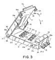
- the connector comprises six conductive contacts 11, a resin insulator 21 having a generally rectangular shape and holding the contacts 11, and a resin or metal cover 31 pivotally supported at a first end 21-1 of the insulator 21.
- the insulator 21 has an upper or a principal surface 21a extending between the first end 21-1 and a second end 21-2 opposite to the first end 21-1.
- Each of the contacts 11 has a leaf-spring contacting portion 13 protruding on the principal surface 21a of the insulator 21, and a terminal portion 15 connected to the contacting portion 13 and extending outward from the insulator 21.
- the contacting portion 13 has elasticity and is located at a position corresponding to each of a plurality of holes 21e formed in the principal surface 21 a of the insulator 21.
- the contacting portion 13 can rise and sink above and below the principal surface 21a of the insulator 21 through the hole 21e.
- the card 41 has a shape and a size adapted to be mounted on the principal surface 21a of the insulator 21. In order to connect the card 41 to the connector, the card 41 is mounted on the principal surface 21a of the insulator 21. When the card 41 is mounted on the principal surface 21a, card contacting portions (not shown) of the card 41 are faced to the contacting portions 13 of the contacts 11 in one-to-one correspondence.
- the second end 21-2 of the insulator 21 is provided with a holding portion 23 for removably supporting one end portion 41a of the card 41.
- the holding portion 23 has a vertical portion 23a extending upward from the second end 21-2 of the insulator 21, and a horizontal portion 23b extending from an upper part of the vertical portion 23a in a horizontal direction to face the principal surface 21 a of the insulator 21.
- the holding portion 23 is provided with a recess 24 extending between the principal surface 21a of the insulator 21 and the horizontal portion 23b and laterally opened.
- the one end portion 41 a of the card 41 is inserted into the recess 24 so that the card 41 is locked by the horizontal portion 23b to be prevented from being separated from the principal surface 21a.
- the insulator 21 is provided with a pair of engaging protrusions 28 respectively formed on a pair of side surfaces 21c in the vicinity of the second end 21-2 to serve as a locking member for locking the cover 31.
- the insulator 21 has a pair of support shaft portions 25 formed on the side surfaces 21c at the one end 21-1.
- Each of the support shaft portions 25 comprises a round-bar-like protrusion.
- the support shaft portions 25 are located at a distance L1 from an end edge 41c of the other end portion 41 b of the card 41 mounted on the principal surface 21a of the insulator 21.
- the cover 31 has a cover principal plate portion 33 of a flat shape, and a pair of cover side plate portions 35 perpendicularly bent from a pair of side edges of the cover principal plate portion 33.
- the cover side plate portions 35 are provided with a pair of pivot portions 35a engaged with the support shaft portions 25, respectively.
- each of the pivot portions 35a is formed by a circular hole fitted with the support shaft portion 25.
- the cover principal plate portion 33 has a leaf-like spring portion 33a having elasticity.
- the spring portion 33a protrudes from a surface faced to the principal surface 21a of the insulator 21 and extends from the cover principal plate portion 33 to the pivot portions 35a.
- the spring portion 33a serves as an acting portion to press the card 41 towards the principal surface 21a when the cover 31 is closed.
- the spring portion 33a has a free end 33b which is located to correspond to a position between the pivot portions 35a and a rotating end 31a which acts as an operating portion to be operated by an operator. In particular, the free end 33b is placed in the vicinity of the pivot portions 35a.
- the cover 31 has a pair of engaging portions 34 formed in the vicinity of the rotating end 31a and perpendicularly bent from a pair of side edges of the cover principal plate portion 33, respectively.
- the engaging portions 34 are provided with engaging holes 34a to be engaged with the engaging protrusions 28 when the cover 31 is closed.
- the one end portion 41a of the card 41 is inserted into the holding portion 23 of the insulator 21 while the cover 31 is opened. Then, the card 41 is placed on the contacting portions 13 of the contacts 11. As a consequence, the card 41 is slightly inclined with respect to the principal surface 21a of the insulator 21.
- the cover 31 is turned around the support shaft portions 25.
- the cover principal plate portion 33 presses the end edge 41c of the card 41 to force the one end portion 41a of the card 41 into the recess 24 of the holding portion 23.
- the free end 33b of the spring portion 33a is brought into contact with an upper surface of the card 41.
- the free end 33b of the spring portion 33a presses the card 41 towards the principal surface 21a of the insulator 21 by the principle of leverage around the support shaft portions 25 as a fulcrum.
- the one end portion 41a of the card 41 is held by the recess 24 of the holding portion 23 to thereby act a support point of the card 41. Therefore, the one end portion 41a of the card 41 is prevented from floating up or being separated from the principal surface 21a of the insulator 21.
- the cover 31 When the cover 31 is completely closed as illustrated in Fig. 6, the engaging holes 34a are engaged with the engaging protrusions 28. Therefore, the cover 31 in a closed state is locked to the insulator 21 and inhibited from being opened.
- the card 41 is pressed downward by the spring portion 33a, particularly, the free end 33b thereof serving as the acting portion to be substantially parallel to the principal surface 21a of the insulator 21.
- the card 41 is brought into press contact with the contacting portions 13 of the contacts 11.
- the contacting portions 13 are brought into contact with the card contacting portions of the card 41 with reactive force.
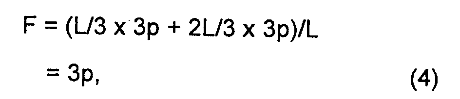
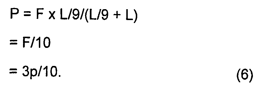
- the connector is designed so that the support shaft portions 25 are located at a distance equal to L/9 from the end edge 41c of the other end portion 41b of the card 41 when the card 41 is set at a predetermined position of the insulator 21.
- L/9 + L the distance from the support shaft portions 25 to the rotating end 31a of the cover 31.
- the connector illustrated in the figures is for use in connection of the card 41, such as the SIM card.
- the cover 31 has a cover principal plate portion 133 of a flat shape and a pair of side plate portions 135 coupled to the cover principal plate portion 133.
- the cover principal plate portion 133 is a part covering the upper surface of the card 41 when the cover 31 is closed.
- the side plate portions 135 are faced to the side surfaces 21c of the insulator 21, respectively.
- Each of the side plate portions 135 is provided with a pivot portion 135a formed by a circular hole.
- the cover 31 is supported to be rotatable around the support shaft portions 25 in the closing direction I and the opening direction II in which the cover 31 is moved towards and away from the principal surface 21a of the insulator 21, respectively.
- a part near the support shaft portions 25 is formed into a leaf spring portion 133a having elasticity.
- the spring portion 133a is substantially separated from the side plate portions 135. The most part of the spring portion 133a extends to be flush or coplanar with a remaining part of the cover principal plate portion 133 when no external force is applied. However, a free end 133b of the spring portion 133a is slightly bent towards the insulator 21.
- the one end portion 41a of the card 41 is inserted into the holding portion 23 of the insulator 21 while the cover 31 is opened. Then, the card 41 is placed on the contacting portions 13 of the contacts 11. As a consequence, the card 41 is slightly inclined with respect to the principal surface 21a of the insulator 21.
- the cover 31 is turned around the support shaft portions 25.
- the spring portion 133a presses the end edge 41c of the card 41 to force the one end portion 41a of the card 41 into the recess 24 of the holding portion 23 and simultaneously presses the card 41 towards the principal surface 21a of the insulator 21.
- the spring portion 133a presses the card 41 against the contacting portions 13 of the connector 11 by the principle of leverage around the support shaft portions 25 as a fulcrum.
- the one end portion 41a of the card 41 is held by the recess 24 of the holding portion 23 and therefore prevented from floating up or being separated from the principal surface 21 a of the insulator 21.
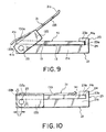
- the free end 133b of the spring portion 133a When the cover 31 is completely closed as illustrated in Fig. 10, the free end 133b of the spring portion 133a is brought into press contact with the upper surface of the card 41.
- the free end 133b of the spring portion 133a serves as the acting portion elastically pressing the card 41 towards the principal surface 21a of the insulator 21.
- the support shaft portions 25 are located at a position between the free end 133b of the spring portion 133a as the acting portion and the rotating end 31a as the operating portion.
- the free end 133b is located near the support shaft portions 25 but is separated from the support shaft portions 25 by a distance L2 along the insulator 21. Therefore, pressing force of the spring portion 133a and a rotary moment by the distance L2 act in the closing direction I. Thus, it is unnecessary to provide a structure for keeping the cover 31 in a closed state.
- the card 41 is pressed downward by the spring portion 133a, particularly, the free end 133b thereof serving as the acting portion to be substantially parallel to the principal surface 21a of the insulator 21.
- the card 41 is brought into press contact with the contacting portions 13 of the contacts 11.
- the contacting portions 13 of the contacts 11 are brought into contact with the card contacting portions of the card 41 with reactive force.
- the connector described in conjunction with Figs. 8 to 10 makes it possible to considerably reduce the operating force required to close the cover 31 as compared with the conventional connector described in conjunction with Fig. 2.
Landscapes
- Physics & Mathematics (AREA)
- General Physics & Mathematics (AREA)
- Engineering & Computer Science (AREA)
- Theoretical Computer Science (AREA)
- Coupling Device And Connection With Printed Circuit (AREA)
- Details Of Connecting Devices For Male And Female Coupling (AREA)
Abstract
Description

Claims (15)
- A connector for use in connecting a card, said connector comprising:an insulator having a first end, a second end opposite to said first end, and a principal surface extending between said first and said second ends, said card being set to face said principal surface;a conductive contact held by said insulator and having a contacting portion protruding from said principal surface to be brought into contact with said card; anda cover openable and closable for bringing said card into press contact with said contacting portion, said cover having a pivot portion rotatably engaged with said first end of said insulator,said insulator having a holding portion formed at said second end to hold one end portion of said card,said cover having an acting portion to be engaged with the other end portion of said card to press said card towards said principal surface of said insulator when said cover is closed.
- The connector according to claim 1, wherein said holding portion has a recess for removably receiving said one end portion of said card.
- The connector according to claim 1, wherein said insulator has a support shaft portion formed at said first end, said pivot portion rotatably engaged with said support shaft portion.
- The connector according to claim 1, wherein said cover comprises:a cover principal plate portion to be faced to said card when said cover is closed; anda spring portion coupled to said cover principal plate portion to serve as said acting portion.
- The connector according to claim 4, wherein said cover principal plate portion presses the other end portion of said card towards said holding portion when said cover is halfway closed.
- The connector according to claim 4, wherein said spring portion presses said card towards said principal surface of said insulator when said cover is halfway closed.
- The connector according to claim 4, wherein said spring portion presses the other end portion of said card towards said holding portion when said cover is halfway closed.
- The connector according to claim 1, wherein said cover has a rotating end to be located near to said holding portion when said cover is closed.
- The connector according to claim 8, wherein said acting portion is located at a position between said pivot portion and said rotating end.
- The connector according to claim 9, wherein said acting portion is located in the vicinity of said pivot portion.
- The connector according to claim 8, wherein said cover has an engaging portion in the vicinity of said rotating end, said insulator having an engaging portion to be engaged with said engaging portion of said cover to inhibit said cover from being opened when said cover is closed.
- The connector according to claim 11, wherein said engaging portion of said cover has an engaging hole while said engaging portion of said insulator has an engaging protrusion to be inserted into said engaging hole when said cover is closed.
- The connector according to claim 8, wherein said pivot portion is located at a position between said acting portion and said rotating end.
- The connector according to claim 13, wherein said acting portion is located in the vicinity of said pivot portion.
- The connector according to claim 8, wherein said pivot portion and said acting portion are spaced from said rotating end at distances substantially equal to each other.
Applications Claiming Priority (2)
| Application Number | Priority Date | Filing Date | Title |
|---|---|---|---|
| JP2002105954 | 2002-04-09 | ||
| JP2002105954A JP3812939B2 (en) | 2002-04-09 | 2002-04-09 | Card connector |
Publications (3)
| Publication Number | Publication Date |
|---|---|
| EP1355384A2 true EP1355384A2 (en) | 2003-10-22 |
| EP1355384A3 EP1355384A3 (en) | 2004-09-08 |
| EP1355384B1 EP1355384B1 (en) | 2007-05-30 |
Family
ID=28672401
Family Applications (1)
| Application Number | Title | Priority Date | Filing Date |
|---|---|---|---|
| EP03252210A Expired - Lifetime EP1355384B1 (en) | 2002-04-09 | 2003-04-08 | Card connector reduced in operating force |
Country Status (5)
| Country | Link |
|---|---|
| US (1) | US6890203B2 (en) |
| EP (1) | EP1355384B1 (en) |
| JP (1) | JP3812939B2 (en) |
| KR (1) | KR100566718B1 (en) |
| CN (1) | CN1269264C (en) |
Cited By (3)
| Publication number | Priority date | Publication date | Assignee | Title |
|---|---|---|---|---|
| EP1885026A1 (en) * | 2006-08-03 | 2008-02-06 | Japan Aviation Electronics Industry, Limited | Connector easily adapted to miniaturization |
| EP2037540A2 (en) | 2007-09-14 | 2009-03-18 | Japan Aviation Electronics Industry, Limited | Socket |
| EP2568779A1 (en) * | 2011-09-09 | 2013-03-13 | Siemens Aktiengesellschaft | Device for electronic contacting of an optical display unit |
Families Citing this family (41)
| Publication number | Priority date | Publication date | Assignee | Title |
|---|---|---|---|---|
| TWM251345U (en) * | 2003-09-30 | 2004-11-21 | Hon Hai Prec Ind Co Ltd | Electrical card connector |
| JP3937340B2 (en) * | 2003-11-28 | 2007-06-27 | 日本電気株式会社 | Card holding structure for portable electronic devices |
| US6913479B1 (en) * | 2004-01-20 | 2005-07-05 | Cheng Uei Precision Industry Co., Ltd. | Electronic card connector |
| JP4073026B2 (en) * | 2004-04-06 | 2008-04-09 | 日本航空電子工業株式会社 | Card connector |
| CN2731774Y (en) * | 2004-07-16 | 2005-10-05 | 上海莫仕连接器有限公司 | Connector for user identification card |
| TWI316713B (en) * | 2004-09-10 | 2009-11-01 | Murata Manufacturing Co | Card-type device |
| US20060076411A1 (en) * | 2004-10-13 | 2006-04-13 | Yen-Hung Chen | Card reading device |
| US7328843B2 (en) * | 2004-10-13 | 2008-02-12 | Jess-Link Products Co., Ltd. | Card reading device |
| DE102004054150B4 (en) * | 2004-11-08 | 2007-11-29 | Lumberg Connect Gmbh | Contacting device for a chip card, in particular for a SIM or USIM card |
| US20060104039A1 (en) * | 2004-11-12 | 2006-05-18 | Yu-Hu Chen | Enclosure for memory cards |
| US7372702B2 (en) * | 2004-12-23 | 2008-05-13 | Intel Corporation | Heat spreader |
| JP4468193B2 (en) | 2005-01-27 | 2010-05-26 | 日本圧着端子製造株式会社 | Card connector |
| US6971919B1 (en) * | 2005-02-07 | 2005-12-06 | Huang-Chou Huang | Memory card connector |
| TWI318338B (en) * | 2005-05-19 | 2009-12-11 | Htc Corp | Portable electronic device |
| US7252231B2 (en) * | 2005-06-03 | 2007-08-07 | Wieson Technologies Co., Ltd. | Card adapter |
| TWI283806B (en) * | 2005-06-07 | 2007-07-11 | Htc Corp | Portable electronic device |
| CN1979973B (en) * | 2005-12-02 | 2010-09-29 | 深圳富泰宏精密工业有限公司 | Chip card holding structure |
| TWM293555U (en) * | 2006-02-07 | 2006-07-01 | Tai Sol Electronics Co Ltd | Compact card connector |
| JP2007261767A (en) * | 2006-03-29 | 2007-10-11 | Saxa Inc | Attaching and detaching structure of card stacker |
| US7118419B1 (en) * | 2006-04-04 | 2006-10-10 | Cheng Uei Precision Industry Co., Ltd. | Foldable SIM card connector |
| CN200941459Y (en) * | 2006-07-14 | 2007-08-29 | 富士康(昆山)电脑接插件有限公司 | Electrical connector assembly |
| US20080254658A1 (en) * | 2007-04-13 | 2008-10-16 | Wang Chin-Chou | Memory card connector |
| JP2008270076A (en) * | 2007-04-24 | 2008-11-06 | Matsushita Electric Works Ltd | Connector |
| JP2008270081A (en) * | 2007-04-24 | 2008-11-06 | Matsushita Electric Works Ltd | Connector and tool for removal |
| US7628634B2 (en) * | 2008-01-28 | 2009-12-08 | Hon Hai Precision Ind. Co., Ltd | Electrical connector with improved package retention device |
| TWM354235U (en) * | 2008-09-01 | 2009-04-01 | Hon Hai Prec Ind Co Ltd | Electrical connector |
| TWM358427U (en) * | 2008-10-28 | 2009-06-01 | Hon Hai Prec Ind Co Ltd | Electrical connector |
| CN101728707B (en) * | 2008-10-31 | 2012-12-19 | 深圳富泰宏精密工业有限公司 | Chip card holding device |
| TWI416925B (en) * | 2008-11-07 | 2013-11-21 | Fih Hong Kong Ltd | Chip card holding device |
| CN101764314B (en) * | 2008-12-23 | 2012-10-31 | 富士康(昆山)电脑接插件有限公司 | Electric connector |
| JP4636628B2 (en) * | 2008-12-25 | 2011-02-23 | 日本航空電子工業株式会社 | connector |
| CN102882069A (en) * | 2011-07-15 | 2013-01-16 | 索尼爱立信移动通讯有限公司 | Circuit board connector and connecting method of circuit board |
| US8747163B2 (en) * | 2012-07-20 | 2014-06-10 | Hon Hai Precision Industry Co., Ltd. | Card connector assembly facilitating heat dissipation of inserted card |
| JP5991928B2 (en) * | 2013-01-16 | 2016-09-14 | 三菱製鋼株式会社 | Switchgear |
| CN103178399B (en) * | 2013-04-15 | 2015-05-13 | 上海摩软通讯技术有限公司 | Card slot for subscriber identity module (SIM) card, and mobile terminal comprising same |
| CN104183984A (en) * | 2013-05-27 | 2014-12-03 | 鸿富锦精密电子(天津)有限公司 | Camera |
| US9786578B2 (en) * | 2014-01-27 | 2017-10-10 | Lenovo Enterprise Solutions (Singapore) Pte. Ltd. | Orthogonally hinged individualized memory module cooling |
| JP6373130B2 (en) * | 2014-09-01 | 2018-08-15 | 株式会社エンプラス | Socket for electrical parts |
| US10051754B2 (en) * | 2016-09-27 | 2018-08-14 | Motorola Mobility Llc | Tray operating system and corresponding methods |
| CN109818173B (en) * | 2019-03-02 | 2021-06-11 | 程慧玲 | SIM card connector |
| US20250338432A1 (en) * | 2024-04-24 | 2025-10-30 | ZT Group Int'l, Inc. | Rotating cold plate assembly, system and method of operating cold plate assembly |
Family Cites Families (12)
| Publication number | Priority date | Publication date | Assignee | Title |
|---|---|---|---|---|
| US4761140A (en) * | 1987-02-20 | 1988-08-02 | Augat Inc. | Minimum insertion force self-cleaning anti-overstress PLCC receiving socket |
| JP2860362B2 (en) * | 1990-03-17 | 1999-02-24 | アムフェノル―トゥヘル、エレクトロニクス、ゲゼルシャフト、ミット、ベシュレンクテル、ハフツング | Contact devices, especially contact devices for subscriber identification modules |
| FR2676566B1 (en) * | 1991-05-13 | 1993-12-17 | Alcatel Cit | CONNECTOR FOR CIRCUIT BOARD. |
| JP3397345B2 (en) * | 1992-08-31 | 2003-04-14 | キヤノン株式会社 | Recording medium loading mechanism |
| US5337220A (en) * | 1993-09-10 | 1994-08-09 | The Whitaker Corporation | Electronic card and connector assembly for use therewith |
| JP3273226B2 (en) | 1994-12-07 | 2002-04-08 | ホシデン株式会社 | Card connector |
| JPH09185973A (en) * | 1995-12-28 | 1997-07-15 | Hirose Electric Co Ltd | Connector for card with surface contact |
| JPH10144391A (en) | 1996-11-12 | 1998-05-29 | Olympus Optical Co Ltd | Memory card loading device |
| EP0977139B1 (en) * | 1998-07-30 | 2000-09-27 | Molex Incorporated | IC Card Connector |
| DE19934964C1 (en) | 1999-07-26 | 2001-03-01 | Amphenol Tuchel Elect | Smart card reader with hinged cover and guidance to position card accurately relative to contacts on base unit |
| FR2803110B1 (en) * | 1999-12-22 | 2002-05-17 | Framatome Connectors Int | CONNECTOR FOR A MICROCIRCUIT CARD AND METHOD FOR MOUNTING SUCH A CARD IN THE CONNECTOR |
| JP4671484B2 (en) * | 2000-10-11 | 2011-04-20 | ケル株式会社 | Card connector |
-
2002
- 2002-04-09 JP JP2002105954A patent/JP3812939B2/en not_active Expired - Fee Related
-
2003
- 2003-04-07 US US10/408,465 patent/US6890203B2/en not_active Expired - Fee Related
- 2003-04-08 EP EP03252210A patent/EP1355384B1/en not_active Expired - Lifetime
- 2003-04-08 KR KR1020030021931A patent/KR100566718B1/en not_active Expired - Fee Related
- 2003-04-09 CN CNB031095364A patent/CN1269264C/en not_active Expired - Fee Related
Cited By (6)
| Publication number | Priority date | Publication date | Assignee | Title |
|---|---|---|---|---|
| EP1885026A1 (en) * | 2006-08-03 | 2008-02-06 | Japan Aviation Electronics Industry, Limited | Connector easily adapted to miniaturization |
| US7371095B2 (en) | 2006-08-03 | 2008-05-13 | Japan Aviation Electronics Industry, Limited | Connector easily adapted to miniaturization |
| EP2037540A2 (en) | 2007-09-14 | 2009-03-18 | Japan Aviation Electronics Industry, Limited | Socket |
| EP2037540A3 (en) * | 2007-09-14 | 2010-03-10 | Japan Aviation Electronics Industry, Limited | Socket |
| US7771211B2 (en) | 2007-09-14 | 2010-08-10 | Japan Aviation Electronics Industry, Limited | Socket with base shell, cover shell and contact member for mounting element within cavity defined by base shell and cover shell |
| EP2568779A1 (en) * | 2011-09-09 | 2013-03-13 | Siemens Aktiengesellschaft | Device for electronic contacting of an optical display unit |
Also Published As
| Publication number | Publication date |
|---|---|
| JP2003303645A (en) | 2003-10-24 |
| US20030190832A1 (en) | 2003-10-09 |
| KR100566718B1 (en) | 2006-04-03 |
| CN1269264C (en) | 2006-08-09 |
| EP1355384B1 (en) | 2007-05-30 |
| CN1450690A (en) | 2003-10-22 |
| EP1355384A3 (en) | 2004-09-08 |
| US6890203B2 (en) | 2005-05-10 |
| KR20030081073A (en) | 2003-10-17 |
| JP3812939B2 (en) | 2006-08-23 |
Similar Documents
| Publication | Publication Date | Title |
|---|---|---|
| EP1355384B1 (en) | Card connector reduced in operating force | |
| US6062889A (en) | Module connector having a switching mechanism | |
| JP3250789B2 (en) | Electrical connector for cards with surface contacts | |
| EP0632542B1 (en) | Card edge connector having a latching device | |
| EP0489125B1 (en) | Circuit board connector having improved latching system | |
| KR20000012057A (en) | Ic card connector | |
| US6887090B2 (en) | Electrical connector with retention clip | |
| TW201019542A (en) | Electrical connector | |
| CN1305246A (en) | Integrated circuit card connector | |
| JP2001244004A (en) | Card holding structure and portable terminal equipped with the same | |
| CN102027642A (en) | Connector | |
| US6024593A (en) | Electronic module connector having a locking cover | |
| US8062048B2 (en) | Electrical connector with pivotally movable cover | |
| US8248819B2 (en) | Chip card holder for portable electronic device | |
| US7628635B2 (en) | Electrical connector with actuating mechanism | |
| US7909631B2 (en) | Electrical connector assembly | |
| US6305971B1 (en) | Flat cable insertion socket | |
| US6565386B1 (en) | Electrical connector | |
| JP4109978B2 (en) | FPC connector and mobile phone using the same | |
| US6699057B2 (en) | Land grid array connector assembly | |
| US20120196469A1 (en) | Electrical connector with dual retention elements | |
| US7014489B2 (en) | Land grid array connector assembly | |
| JP2001332361A (en) | Flat cable connector | |
| JP3231690B2 (en) | Socket for IC package | |
| JP2001052120A (en) | Card reading device and pressing member for the device |
Legal Events
| Date | Code | Title | Description |
|---|---|---|---|
| PUAI | Public reference made under article 153(3) epc to a published international application that has entered the european phase |
Free format text: ORIGINAL CODE: 0009012 |
|
| AK | Designated contracting states |
Kind code of ref document: A2 Designated state(s): AT BE BG CH CY CZ DE DK EE ES FI FR GB GR HU IE IT LI LU MC NL PT RO SE SI SK TR |
|
| AX | Request for extension of the european patent |
Extension state: AL LT LV MK |
|
| PUAL | Search report despatched |
Free format text: ORIGINAL CODE: 0009013 |
|
| AK | Designated contracting states |
Kind code of ref document: A3 Designated state(s): AT BE BG CH CY CZ DE DK EE ES FI FR GB GR HU IE IT LI LU MC NL PT RO SE SI SK TR |
|
| AX | Request for extension of the european patent |
Extension state: AL LT LV MK |
|
| 17P | Request for examination filed |
Effective date: 20050301 |
|
| AKX | Designation fees paid |
Designated state(s): FI GB SE |
|
| REG | Reference to a national code |
Ref country code: DE Ref legal event code: 8566 |
|
| GRAP | Despatch of communication of intention to grant a patent |
Free format text: ORIGINAL CODE: EPIDOSNIGR1 |
|
| GRAS | Grant fee paid |
Free format text: ORIGINAL CODE: EPIDOSNIGR3 |
|
| GRAA | (expected) grant |
Free format text: ORIGINAL CODE: 0009210 |
|
| AK | Designated contracting states |
Kind code of ref document: B1 Designated state(s): FI GB SE |
|
| REG | Reference to a national code |
Ref country code: GB Ref legal event code: FG4D |
|
| RIN1 | Information on inventor provided before grant (corrected) |
Inventor name: SUZUKI, KEIICHIROC/O JAPAN AVIATION ELECTRONICS IN Inventor name: NATORI, AKIRAC/O JAPAN AVIATION ELECTRONICS INDUST Inventor name: SHIMADA, MASAAKI C/O JAPAN AVIATION ELECTRONICS IN Inventor name: MATSUNAGA, AKIHIRO,C/O JAPAN AVIATION ELECTRONICS |
|
| REG | Reference to a national code |
Ref country code: SE Ref legal event code: TRGR |
|
| PLBE | No opposition filed within time limit |
Free format text: ORIGINAL CODE: 0009261 |
|
| STAA | Information on the status of an ep patent application or granted ep patent |
Free format text: STATUS: NO OPPOSITION FILED WITHIN TIME LIMIT |
|
| 26N | No opposition filed |
Effective date: 20080303 |
|
| EUG | Se: european patent has lapsed | ||
| PG25 | Lapsed in a contracting state [announced via postgrant information from national office to epo] |
Ref country code: SE Free format text: LAPSE BECAUSE OF NON-PAYMENT OF DUE FEES Effective date: 20080409 |
|
| PGFP | Annual fee paid to national office [announced via postgrant information from national office to epo] |
Ref country code: GB Payment date: 20150408 Year of fee payment: 13 |
|
| GBPC | Gb: european patent ceased through non-payment of renewal fee |
Effective date: 20160408 |
|
| PG25 | Lapsed in a contracting state [announced via postgrant information from national office to epo] |
Ref country code: GB Free format text: LAPSE BECAUSE OF NON-PAYMENT OF DUE FEES Effective date: 20160408 |
|
| PGFP | Annual fee paid to national office [announced via postgrant information from national office to epo] |
Ref country code: FI Payment date: 20190409 Year of fee payment: 17 |
|
| REG | Reference to a national code |
Ref country code: FI Ref legal event code: MAE |
|
| PG25 | Lapsed in a contracting state [announced via postgrant information from national office to epo] |
Ref country code: FI Free format text: LAPSE BECAUSE OF NON-PAYMENT OF DUE FEES Effective date: 20200408 |