EP1355177A1 - Fusion splicing device and fusion splicing method - Google Patents
Fusion splicing device and fusion splicing method Download PDFInfo
- Publication number
- EP1355177A1 EP1355177A1 EP01999845A EP01999845A EP1355177A1 EP 1355177 A1 EP1355177 A1 EP 1355177A1 EP 01999845 A EP01999845 A EP 01999845A EP 01999845 A EP01999845 A EP 01999845A EP 1355177 A1 EP1355177 A1 EP 1355177A1
- Authority
- EP
- European Patent Office
- Prior art keywords
- optical fiber
- fusion splicing
- section
- type
- data
- Prior art date
- Legal status (The legal status is an assumption and is not a legal conclusion. Google has not performed a legal analysis and makes no representation as to the accuracy of the status listed.)
- Granted
Links
Images


Classifications
-
- G—PHYSICS
- G02—OPTICS
- G02B—OPTICAL ELEMENTS, SYSTEMS OR APPARATUS
- G02B6/00—Light guides; Structural details of arrangements comprising light guides and other optical elements, e.g. couplings
- G02B6/24—Coupling light guides
- G02B6/255—Splicing of light guides, e.g. by fusion or bonding
-
- G—PHYSICS
- G02—OPTICS
- G02B—OPTICAL ELEMENTS, SYSTEMS OR APPARATUS
- G02B6/00—Light guides; Structural details of arrangements comprising light guides and other optical elements, e.g. couplings
- G02B6/24—Coupling light guides
- G02B6/255—Splicing of light guides, e.g. by fusion or bonding
- G02B6/2553—Splicing machines, e.g. optical fibre fusion splicer
-
- G—PHYSICS
- G02—OPTICS
- G02B—OPTICAL ELEMENTS, SYSTEMS OR APPARATUS
- G02B6/00—Light guides; Structural details of arrangements comprising light guides and other optical elements, e.g. couplings
- G02B6/24—Coupling light guides
- G02B6/255—Splicing of light guides, e.g. by fusion or bonding
- G02B6/2551—Splicing of light guides, e.g. by fusion or bonding using thermal methods, e.g. fusion welding by arc discharge, laser beam, plasma torch
-
- G—PHYSICS
- G02—OPTICS
- G02B—OPTICAL ELEMENTS, SYSTEMS OR APPARATUS
- G02B6/00—Light guides; Structural details of arrangements comprising light guides and other optical elements, e.g. couplings
- G02B6/24—Coupling light guides
- G02B6/255—Splicing of light guides, e.g. by fusion or bonding
- G02B6/2555—Alignment or adjustment devices for aligning prior to splicing
Definitions
- the present invention relates to an apparatus and method for fusion splicing end portions of optical fibers for communication by discharge heating and the like, and more particularly to an apparatus and method for fusion splicing the optical fibers under fusion splicing conditions suitable for types of optical fibers by automatically determining the types of optical fibers.
- optical fibers including a single mode optical fiber (hereinafter referred to as an SM fiber), a multi-mode optical fiber (hereinafter referred to as an MM fiber), a dispersion shifted optical fiber (hereinafter referred to as a DS fiber), and an erbium doped optical fiber (hereinafter referred to as an ED fiber), are provided.
- SM fiber single mode optical fiber
- MM fiber multi-mode optical fiber
- DS fiber dispersion shifted optical fiber
- ED fiber erbium doped optical fiber
- these optical fibers are fusion spliced by a fusion splicing machine, it is required to make splicing under the fusion splicing conditions (discharge current, discharge time, etc.) suitable for each optical fiber.
- the type of the optical fiber may be mistaken, in which there is the risk that a splicing failure occurs due to unsuitable fusion splicing conditions for the optical fibers.
- the fusion splicing of the optical fibers is not necessarily conducted under the light working environment, but may be conducted under the dark environment within a manhole, for example.
- the coating material of the optical fiber may be colored to identify the type of optical fiber, but recognized by mistake. If image observing means of high resolution and high magnification is employed for an image monitor of the fusion splicing machine, a core portion as minute as 3 to 10 ⁇ m can be observed, but the optical fibers of similar profiles may be recognized by mistake.
- a splicing loss is greater, whereby the splicing of optical fibers must be made again from the beginning.
- a series of operations including the removal of a falsely spliced portion, the removal of the coatings for the end portion of optical fiber and cutting the end portion must be performed from the beginning, resulting in a worse working efficiency, and the operator becomes nervous.
- One of the conventional techniques to solve the above problem is well-known in which the optical fibers are spliced under the optimal fusion splicing conditions by identifying the type of optical fiber through image processing, as disclosed in JP-A-8-21923.
- This conventional technique involves identifying the brightness level profile of the optical fiber observed at the fusion spliced portion through image processing. Then the brightness level profile (hereinafter referred to as a brightness profile) for each of various types of optical fiber is previously stored. Thereafter, the type of optical fiber is designated by collation with the brightness profile of optical fiber tobe fusion spliced.
- the optical fibers are fusion spliced by designating the type of optical fiber and selecting the optimal fusion splicing conditions from among the stored fusion splicing conditions for each type of optical fiber.
- the type of optical fiber is estimated by obtaining the brightness profile from an observed image of the optical fiber
- the brightness profile may be varied or different between the same type of optical fibers, depending on the focus or optical characteristics of the observed image, and the manufacturing conditions of the optical fiber.
- the conventional technique shows an example of a fusion splicing machine for ribbonized optical fiber, in which image observing means, typically with a low magnification and a long depth of focus, has a small numerical aperture of 0.1 or less.
- image observing means typically with a low magnification and a long depth of focus
- the resolution can not be sufficiently obtained, whereby it is difficult to acquire the detailed information from the brightness profile.
- a DS fiber and an ED fiber have both a core diameter of 4 ⁇ m, with quite similar brightness profiles, and practically is difficult to discriminate from the comparison between the brightness profiles.
- the comparison between the brightness profiles is made employing the interval between displaced points near the center of fiber axis. Accordingly, although this technique is effective when the brightness profile is clearly different depending on the type of optical fiber, it is difficult to discriminate all the types of optical fiber.
- the present invention has been achieved in the light of the above-mentioned circumstance, and it is an object of the invention to provide an apparatus and method for fusion splicing the optical fibers under the fusion splicing conditions suitable for respective optical fibers in which the types of optical fibers can be fully discriminated.
- the present invention provides a fusion splicing apparatus for fusion splicing end portions of optical fibers by butt discharging, characterized by comprising an image observing mechanism for observing the end portions of the optical fibers, an image processing section for measuring parameter data of a brightness distribution waveform of optical fiber in cross section from a picked up image, a fuzzy operation section for obtaining a degree of attribution for the measured parameter data from a fuzzy operation data registered in advance in a data registering section and identifying the type of optical fiber through a fuzzy operation, a collating section for collating the identified type of optical fiber with fusion splicing conditions for each type of optical fiber registered in advance in a fusion splicing condition registering section, a display unit for displaying a collation result, a fusion splicing mechanism, and a control section.
- this invention provides a fusion splicing method for fusion splicing end portions of optical fibers by butt discharging, characterized by including observing the end portions of the optical fibers in an image observing mechanism, measuring parameter data of a brightness distribution waveform of optical fiber in cross section from a picked up image in an image processing section, obtaining a degree of attribution for the measured parameter data from fuzzy operation data registered in advance and identifying the type of optical fiber through a fuzzy operation in a fuzzy operation section, collating the identified type of optical fiber with fusion splicing conditions for each type of optical fiber registered in advance in a collating section, displaying the collation result, and fusion splicing the optical fibers in a fusion splicing mechanism.
- reference numeral 1 denotes an image observing mechanism
- 2 denotes an image processing section
- 3 denotes a data registering section
- 4 denotes a fuzzy operation section
- 5 denotes a fusion splicing condition registering section
- 6 denotes a collating section
- 7 denotes a monitor display unit
- 8 denotes a control section
- 9 denotes a fusion splicing mechanism
- 11 denotes an optical fiber
- 12 denotes a microscope
- 13 denotes a light source
- 14 denotes a mirror
- 15 denotes a focus driving section.
- Fig. 1 is a block diagram for explaining an embodiment of the present invention.
- reference numeral 1 denotes an image observing mechanism
- 2 denotes an image processing section
- 3 denotes a data registering section
- 4 denotes a fuzzy operation section
- 5 denotes a fusion splicing condition registering section
- 6 denotes a collating section
- 7 denotes a monitor display unit
- 8 denotes a control section
- 9 denotes a fusion splicing mechanism
- 11 denotes an optical fiber
- 12 denotes a microscope
- 13 denotes a light source
- 14 denotes a mirror
- 15 denotes a focus driving section.
- the image observing mechanism 1 picks up an image of a pair of optical fibers 11 butted and held by the fusion splicing mechanism (not described in detail and not shown) from two directions using the microscopes 12 with the CCD cameras disposed orthogonal to each other.
- the light source 13 for illumination to pick up the image is disposed to illuminate the optical fiber 11 via the mirror 14 from the background side.
- the microscope 12 of high magnification and high resolution has the focus driving section 15 for adjusting-the focal point, which is controlled by the control section 8 with a microprocessor.
- An optical fiber image observed by the microscope 12 is measured to acquire the predetermined data of optical fiber from the brightness distribution waveform in the image processing section 2.
- a degree of attribution is calculated by referring to the data of a fuzzy data memory registered in advance in the data registering section 3 in the fuzzy operation section 4.
- the degree of attribution for each of a plurality of types of optical fiber is compared and calculated to select a candidate for the type of optical fiber, verify the validity of the candidate and decide the type of optical fiber.
- the collating section 6 collates the type of optical fiber and the fusion splicing conditions of that type registered in advance in the fusion splicing condition registering section 5. If the fusion splicing conditions are matched with the set conditions, the optical fibers are spliced under the set fusion splicing conditions using the fusion splicing mechanism 9 . If the fusion splicing conditions are unmatched with the set conditions, an instruction for retry or splicing is made. The collation result of the collating section 6 is displayed on the monitor display unit 7. The execution of fusion splicing is made under the registered fusion splicing conditions by controlling the fusion splicing mechanism 9 in the control section 8 with the microprocessor. The details of each section will be described below.
- the image processing section 2 comprises image acquisition means 2a for acquiring the optical fiber image picked up by the image observing mechanism 1, waveform detecting means 2b for detecting the image as a brightness distribution waveform (hereinafter referred to as a brightness profile), and data measuring means 2c for measuring the data from the brightness profile.
- image acquisition means 2a for acquiring the optical fiber image picked up by the image observing mechanism 1
- waveform detecting means 2b for detecting the image as a brightness distribution waveform (hereinafter referred to as a brightness profile)
- data measuring means 2c for measuring the data from the brightness profile.
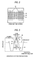
- Fig. 2 is a view showing an image pick-up screen of the optical fibers to be acquired by the image acquisition means 2a.
- the ends of a pair of optical fibers to be fusion spliced are butted before being fusion spliced.
- Light passing through the optical fiber is condensed because the optical fiber serves as a rod lens, and has a brightness distribution where light is centrally condensed. Therefore, the transmitting light is condensed in the dark portion as a shadow against the background light brightness.
- a strip image is displayed, consisting of a bright portion 21 of the transmitting light appearing horizontally in the central section and a dark portion 22 as a shadow appearing on both the upper and lower sides of the bright portion 21.
- a brighter portion 23 appears in the center of the bright portion due to a core portion having a different refractive index.
- This picked up image is extracted along a sampling line 24 and arithmetically operated to obtain the brightness profile. The sampling is made at several points (four to five points), whereby the average value data is obtained.
- Fig. 3 is a graph showing the brightness profile of the optical fiber in cross section for the image of Fig. 2, in which the brightness of the optical fiber is indicated along the longitudinal axis and the position in diameter direction is indicated along the transverse axis.
- This brightness profile consists of a bright portion 25 in the central section, a dark portion 26 on both sides thereof, and a bright portion indicating the background brightness in its outside.
- the bright portion 25 in the central section has a projecting crest 27 in the center, and crests 28 on the left and right sides thereof.
- the number of crests, its interval and the height of crest may be different depending on the type of optical fiber.
- the central crest 27 indicates the core portion, and is relatively easily identified to be located almost in the center of the optical fiber.
- a trough 30 is also easily recognized on both sides of the central crest 27.
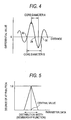
- a differential value waveform is obtained as shown in Fig. 4.
- the position and number where the differential value is equal to zero are different depending on the number of crests, but a vertex position 29 of the crest 27 for the core portion is easy to obtain.
- the distance between the maximum differential values across the vertex position 29 as the center where the differential value is zero is defined as a core diameter A
- the distance between the differential values of zero on both sides of the vertex position 29 is defined as a core diameter B.
- the core diameter A indicates a variable density boundary distance (width) at the middle abdomen of the crest 27 in the core portion
- the core diameter B indicates a distance between the troughs 30.
- the number of crests is equal to the number of peaks in the angular waveform, and a brightness difference (or a core height) between the vertex position 29 of the crest 27 and the trough 30 in the core portion is measured and acquired as the data.
- the height of crest 27 may be represented by the brightness level from the dark portion 26, but not from the trough 30, or the contrast may be obtained as the data.
- the SM fiber has a waveform of three crests as shown in Fig. 3, in which a central crest indicates the core portion.
- Each of the DS fiber and the ED fiber has actually a small core diameter and a large difference in refractive index between the core and the cladding, whereby the central crest 27 for the core portion is slender and higher.
- the refractive index distribution is convex, the light condensing is so complex that the bottom of the crest is spread or the number of crests is increased.
- the MM fiber (GI type) has a refractive index that gradually changes, with the height of crest tending to decrease conspicuously.
- the brightness profile of optical fiber is different depending on the type of optical fiber, and measured by the data measuring means 2c.
- the degree of attribution is substituted for the data measured from the brightness profile by the fuzzy operation section 4.
- the type of optical fiber is identified from the degree of attribution obtained. In making a fuzzy operating process, it is required to prepare for the membership function. Turning back to Fig. 1, the data registering section 3 will be described below.
- the data registering section 3 stores in advance the data for discriminating the types of optical fibers to be fusion spliced.
- the data registering section 3 includes data processing means 3a and a fuzzy data memory 3b.
- the data processing means 3a creates the membership function data by calculating an average value and a standard deviation value from the data measured by the image processing section. Also, it acquires the newly measured data as the additional data and updates the data.
- the fuzzy data memory 3b accumulates the optical fiber type data subjected to the fuzzy operation by the data processing means and is used for calculating the degree of attribution for the optical fiber that is newly measured.
- Fig. 5 is a typical example of the membership function useful in the fuzzy operation of the invention, in which the membership function is a convex type. This function represents the fuzziness of data in the distribution width, and has a probability that the degree of attribution is one at the central value. However, other forms or the general fuzzy theory may be employed, so long as the distribution of data is represented by the function.
- the membership function of Fig. 5 is represented by a triangle with a vertex at the central value and the distribution width as the bottom side, in which the degree of attribution is taken along the longitudinal axis, and the parameter data along the transverse axis.
- the central value is an average value of data and the distribution width is a standard deviation value. By making the distribution width several times (e.g., five times on one side) the standard deviation value, the membership function is so reasonable that measurement values are not deviated from the average value and do not become zero over the broad range.
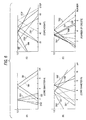
- Fig. 6 shows the examples of the membership function from the actual measurement data.
- Fig. 6 (A) is a membership function with the core diameter A
- Fig. 6(B) is a membership function with the core diameter B
- Fig. 6(C) is a membership function with the core height
- Fig. 6(D) is a membership function with the number of crests.
- the core diameter B distance between the troughs 30 in Fig.
- Fig. 7 is a graph showing the variation of the brightness profile when the focus positions (three positions) of the SM fiber are changed. As shown in Fig. 5, the brightness profile is varied by changing the focus position for picking up the image even with the exactly same optical fiber. Accordingly, it is necessary to extend the distribution width of the membership function by intentionally dispersing the profile, including the values measured at the positions before and after the focus set-up position, to increase the adaptability.
- the membership function is necessary to be created in advance from the known data or by the data registration.
- the fusion splicing is made by newly discriminating the type of optical fiber, it is possible that the measured data for discrimination is newly added to the already existing membership function.
- the types of optical fiber can be further distinguished by adding the new fiber as defined by the user successively and learning it. By the successive addition of data, the amount of database for discrimination can be increased, and the type of optical fiber can be identified more minutely and precisely.
- the optimization can be performed due to the addition of data. Since the weight in adding the data is changed by changing the number n, the extent of adaptability or the learning speed (number of additions) can be set up.
- the fuzzy operation section 4 includes fuzzy operating means 4a, comparing calculating means 4b, candidate verifying means 4c and fiber type deciding means 4d.
- the fuzzy operating means 4a substitutes the degree of attribution for the data measured by the image processing section 2. The substitution of the degree of attribution is made for the measured data as the type of optical fiber from the membership function of Fig. 6 stored in the fuzzy data memory 3b.
- Table 1 lists an instance of calculating the degree of attribution. The numerical values of Table 1 are only exemplary for explanation, but differ from the actual values.
- Table 1 The calculation of Table 1 will be described below. Assuming that the number of measured crests for the bright portion is three, it will be found from the membership function of Fig. 6D that the SM fiber, the MM fiber, the DS1 fiber and the ED fiber have the degrees of attribution of 0.8, 0.9, 0.9 and 0.5, respectively. Similarly, assuming that the core diameter B is 9 ⁇ m, and the core height is 60 steps, those optical fibers have the degrees of attribution for the type of optical fiber as listed in Table 1, which are calculated from the membership function for each parameter of Fig. 6.
- the numerical values calculated by the fuzzy operating means 4a are employed by the comparing calculating means 4b to select a candidate for the type of optical fiber of measured data.
- the candidate selection is made using a minimum/maximum method.
- This minimum/maximum method involves firstly selecting the minimum degree of attribution for each type of optical fiber.
- the SM fiber is 0.5 for the core diameter B
- the MM fiber is 0.3 for the core height
- the DS1 fiber is 0.8 for the core diameter B
- the ED fiber is zero for the core diameter B.
- the maximum degree of attribution is selected from among the minimum degrees of attribution for each type of optical fiber. That is, since the maximum degree of attribution is 0.8 for the DS1 fiber, it is judged that the candidate for the type of optical fiber is the DS1 fiber.
- F is a degree of confidence having a numerical value of the degree of attribution
- m is a membership function
- i, j, k, l,..” are parameters
- t is the type of optical fiber.
- F max [min (m i , t, m j ,t, m k , t, m l , t, ..)]t
- the type of optical fiber as determined in the above manner is verified by the candidate verifying means 4c.
- the verification of the candidate is uncertain, when the degree of attribution for the type of optical fiber determined as the candidate is small, because the degree of attribution selected for the candidate is the degree of confidence. Accordingly, if a threshold is set for the degree of attribution, the identification of the candidate may be unclear when the candidate has the degree of attribution smaller than this threshold.
- two candidates having the same maximum degree of attribution or with a smaller difference in the degree of attribution between the first and second candidates than a certain value, if any, are displayed. In this case, the type of optical fiber may be decided by making the measurement again, or on the basis of the ranking.
- the result of determining the type of optical fiber is displayed, along with the fiber image, on the monitor display unit 7, as shown in Fig. 8.
- the determination for the type of optical fiber is made separately for each of the left and right optical fibers.
- the type of optical fiber is displayed for each of the left and right optical fibers, in which the splicing conditions may be displayed. The operator may be prompted to perform the fusion splicing or retry by once interrupting the operation during this display. In deciding the type of optical fiber, the type of optical fiber and the measurement data are added to the data registering section 3.
- the fusion splicing condition registering section 5 includes setting means 5a for inputting the splicing conditions and a memory 5b for storing the splicing conditions.
- the splicing conditions include the preheating time, end face spacing, discharge current, and discharge time for each type of optical fiber, for example.
- the fusion splicing is performed automatically or by confirmation of the operator. If the collation results are matched with the type of optical fiber and the fusion splicing conditions selected before hand by the operator prior to splicing, the fusion splicing is automatically performed without interruption. In this case, the results are not displayed on the monitor display unit 7, thereby lightening the labor of the operator. Only if the collation results are unmatched with the type of optical fiber and the fusion splicing conditions, the results are displayed on the monitor display unit 7 to prompt the operator to perform the fusion splicing or retry in accordance with the display contents.
- the fusion splicing itself is performed by driving the fusion splicing mechanism 9 (not shown in detail) on the basis of the above-mentioned fusion splicing condition under the control of the control section 8 with microprocessor, employing the well-known method and mechanism.
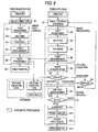
- a fusion splicing method of the invention will be described below.
- the automatic processing is shown within the frame of the dotted line, and the manual processing is shown outside the frame.
- a flow of fiber registration to create the fiber data for determining the type of optical fiber is shown on the left side of the flowchart, and a flow of fusion splicing is shown on the right side.
- a pair of optical fibers with clear type of optical fiber are set in the fusion splicing apparatus, as is the case of fusion splicing.
- the optical fibers are set.
- the type of optical fiber one of the choices if already known or its name if unknown
- the next steps D2 to D5 involve the image processing of optical fiber.
- step D2 light adjustment is made by the image observing mechanism (Fig. 1) so that an observed picked-up image of the optical fiber may be in an optimal state. Then, at step D3, the butt position is adjusted so that the pick up position of the optical fiber may be located in the center of the screen to be easily observed. Thereafter, at step D4, focusing is made to set the focal point of observed image at a preset focus position.
- the data of the optical fiber is measured.
- the data measurement is made by sampling several points on a butt screen (Fig. 2) of the optical fiber and creating the brightness profile (Fig. 3) of the optical fiber through the image processing.
- a differentiating processing (Fig. 4) is performed on the basis of this brightness profile to acquire the parameter data, including the core diameter, core height and the number of crests.
- the measured data is processed.
- the data processing involves creating the membership function (Figs. 5 and 6) on the basis of the measured data, in which the created data is registered as the fiber data in the database.
- the optical fiber is removed from the fusion splicing apparatus.
- the type of optical fiber may be already known but uncertain, or unknown absolutely.
- a pair of optical fibers to be fusion spliced are set in the fusion splicing apparatus as is the case with the fiber registration.
- the fusion splicing conditions are selected and input.
- the fusion splicing conditions that are relevant with the type of optical fiber may be selected by the type of optical fiber.
- the fusion splicing conditions are selected from among the pieces of splicing condition data registered in the database on the basis of the presumption of the type of optical fiber, if it is estimated in advance. If the type of optical fiber is unknown absolutely, an item "automatic selection" provided on the selection menu may be chosen.
- the light adjustment at step S2, the butting at step S3, the focusing at step S4, and the fiber measurement at step S5 are involved in the image processing as previously described, with the exactly same flow as the fiber registration, and not described here.
- the data measured in the fiber measurement at step S5 may be added to the database, as needed, or the processing of fiber registration at step D6 may be performed in parallel.
- the steps S6 to S8 are involved in the determination of the type of optical fiber and the splicing collation of the fusion splicing conditions.
- the type of optical fiber that has been set is identified. Identification of the type of optical fiber is made by calculating the degree of attribution for the data measured at step S5 by referring to the fuzzy operated data (Fig. 6) in the database, and identifying the type of optical fiber by the minimum maximum method.
- the fusion splicing conditions for each type of optical fiber registered in the database are collated. If they are matched with the fusion splicing conditions selected at step S1, the operation proceeds to the next fusion splicing processing. If unmatched with the fusion splicing conditions selected at step S1, the collation result is displayed on the display unit at steps 8. If the splicing is determined to be unsuitable from the displayed data, the operation returns to step S1 to set the fusion splicing conditions again. If it is determined that the splicing is possible though the displayed data is unmatched, the operation proceeds to the next fusion splicing processing.
- the next steps S9 to S13 involve performing the fusion splicing of the optical fibers by the well-known method.
- First of a11 in measuring the end face of optical fiber at step S9, the end face spacing between optical fibers, the end face shape of the optical fiber, and attachment of dust are measured.
- step S10 if the end face shape is checked to be false, the optical fiber is removed from the apparatus, and cut again. If there is no abnormality on the end face of optical fiber, the optical fibers are aligned with their axes at step S11. Subsequently, at step S12, the optical fibers are fusion spliced at a discharge current and for a discharge time set in the fusion splicing conditions.
- step S12 finish of the spliced portion for thickness or thinness, the mixture of dust and air bubbles, the inclination of core portion, and misalignment are checked. Thereafter, at step S14, the optical fiber is removed from the fusion splicing apparatus.
- a single core optical fiber has been described above, but the invention is also applicable to a ribbonized optical fiber, employing the image observing mechanism with high magnification.
- the ribbonized optical fiber is apparently composed of optical fibers of the same kind, one of the ribbonized optical fibers may be subjected to the identification processing.
- the optical fibers can be suitably fusion spliced by identifying all the types of optical fibers correctly and selecting the fusion splicing conditions suitable for the type of optical fiber. Also, it is possible to add to the database for identification automatically, and increase the identification precision.
Landscapes
- Physics & Mathematics (AREA)
- Engineering & Computer Science (AREA)
- Plasma & Fusion (AREA)
- General Physics & Mathematics (AREA)
- Optics & Photonics (AREA)
- Mechanical Coupling Of Light Guides (AREA)
Abstract
Description
| Type | Number of crests (3) | Core diameter B (9µm) | Core height (60) | Minimum |
| SM | 0.8 | 0.5 | 0.8 | 0.5 |
| MM | 0.9 | 0.8 | 0.3 | 0.3 |
| DS1 | 0.9 | 0.8 | 0.9 | 0.8 |
| ED | 0.5 | 0 | 0.8 | 0 |
| Maximum | 0.8 |
| Fiber Type | Number of Correct | Correct Answer Ratio |
| SM | 36/36 | 100% |
| MM | 35/36 | 97% |
| DS1 (Normal type) | 34/36 | 94% |
| DS2 (Expanded core area type) | 36/36 | 100% |
| ED | 35/36 | 97% |
Claims (11)
- A fusion splicing apparatus for fusion splicing end portions of optical fibers by butt discharging, characterized by comprising:an image observing mechanism for observing the end portions of the optical fibers;an image processing section for measuring a parameter data of a brightness distribution waveform of optical fiber in cross section from a picked up image;a fuzzy operation section for obtaining a degree of attribution for the measured parameter data from a fuzzy operation data registered in advance in a data registering section and identifying the type of optical fiber through a fuzzy operation;a collating section for collating the identified type of optical fiber with fusion splicing conditions for each type of optical fiber registered in advance in a fusion splicing condition registering section;a display unit for displaying the collation result;a fusion splicing mechanism; anda control section.
- The fusion splicing apparatus according to claim 1, characterized in that said parameter data includes at least the number of crests, a core diameter, and a core height of said brightness distribution waveform.
- The fusion splicing apparatus according to claim 2, characterized in that said data registering section comprises data processing means for retrieving said parameter data and creating the fuzzy operation data.
- The fusion splicing apparatus according to any one of claims 1 to 3, characterized in that the fuzzy operation data registered in advance is a membership function of an average value and a standard deviation value for the parameter data of the brightness distribution waveform of the optical fiber in cross section.
- A fusion splicing method for fusion splicing end portions of optical fibers by butt discharging, characterized by including:observing the end portions of said optical fibers in an image observing mechanism;measuring a parameter data of a brightness distribution waveform of optical fiber in cross section from a picked up image in an image processing section;obtaining a degree of attribution for the measured parameter data from a fuzzy operation data registered in advance and identifying the type of optical fiber through a fuzzy operation in a fuzzy operation section;collating the identified type of optical fiber with fusion splicing conditions for each type of optical fiber registered in advance in a collating section;displaying the collation result; andfusion splicing the optical fibers in a fusion splicing mechanism.
- The fusion splicing method according to claim 5, characterized in that said parameter data includes at least the number of crests, a core diameter, and a core height of said brightness distribution waveform.
- The fusion splicing method according to claim 5 or 6, characterized in that the fuzzy operation data registered in advance is a membership function of an average value and a standard deviation value for the parameter data of the brightness distribution waveform of the optical fiber in cross section.
- The fusion splicing method according to claim 7, characterized in that said membership function involves the parameter data where said brightness distribution waveform has a focal point for picking up an optical fiber image shifted from a set-up position.
- The fusion splicing method according to claim 7 or 8, characterized in that said membership function has additionally said measured parameter data of the optical fiber to be fusion spliced newly.
- The fusion splicing method according to any one of claims 5 to 7, characterized by further including obtaining degree of attribution for each of plural pieces of said measured parameter data for each of plural types of optical fiber to make the fuzzy operation, selecting the minimum value of said degrees of attribution for each type of optical fiber, selecting the maximum value among said selected minimum values, and identifying the type of optical fiber indicating said selected maximum value as the type of measured optical fiber.
- The fusion splicing method according to claim 5, characterized in that if the collation result of the splicing conditions for the identified type of optical fiber is matched with the preset splicing conditions, the fusion splicing is performed without displaying the collation result.
Applications Claiming Priority (3)
| Application Number | Priority Date | Filing Date | Title |
|---|---|---|---|
| JP2000369681A JP4367597B2 (en) | 2000-12-05 | 2000-12-05 | Fusion splicing device and splicing splicing method |
| JP2000369681 | 2000-12-05 | ||
| PCT/JP2001/010580 WO2002046814A1 (en) | 2000-12-05 | 2001-12-04 | Fusion splicing device and fusion splicing method |
Publications (3)
| Publication Number | Publication Date |
|---|---|
| EP1355177A1 true EP1355177A1 (en) | 2003-10-22 |
| EP1355177A4 EP1355177A4 (en) | 2005-06-15 |
| EP1355177B1 EP1355177B1 (en) | 2008-09-10 |
Family
ID=18839686
Family Applications (1)
| Application Number | Title | Priority Date | Filing Date |
|---|---|---|---|
| EP01999845A Expired - Lifetime EP1355177B1 (en) | 2000-12-05 | 2001-12-04 | Fusion splicing device and fusion splicing method |
Country Status (10)
| Country | Link |
|---|---|
| US (1) | US6966708B2 (en) |
| EP (1) | EP1355177B1 (en) |
| JP (1) | JP4367597B2 (en) |
| KR (1) | KR100646124B1 (en) |
| CN (1) | CN1234030C (en) |
| AU (2) | AU2002222577B2 (en) |
| CA (1) | CA2431138C (en) |
| DE (1) | DE60135781D1 (en) |
| TW (1) | TWI233507B (en) |
| WO (1) | WO2002046814A1 (en) |
Cited By (2)
| Publication number | Priority date | Publication date | Assignee | Title |
|---|---|---|---|---|
| GB2421592A (en) * | 2004-12-27 | 2006-06-28 | Sumitomo Electric Industries | Method of fusion splicing optical fibers. |
| EP2752695A4 (en) * | 2011-09-02 | 2014-08-06 | Fujikura Ltd | FUSION SPLICE DEVICE AND METHOD FOR DISTINGUISHING OPTICAL FIBERS |
Families Citing this family (43)
| Publication number | Priority date | Publication date | Assignee | Title |
|---|---|---|---|---|
| JP4101037B2 (en) * | 2002-11-18 | 2008-06-11 | 古河電気工業株式会社 | Optical fiber splice loss reduction method and splice loss reduction apparatus |
| US6811329B2 (en) * | 2002-12-12 | 2004-11-02 | Fitel Usa Corp. | Systems and methods for monitoring pre-splice heat treatment of optical fibers |
| JP4032960B2 (en) * | 2002-12-20 | 2008-01-16 | 住友電気工業株式会社 | Optical fiber fusion splicer |
| JP4102707B2 (en) * | 2003-05-19 | 2008-06-18 | 株式会社フジクラ | Constant polarization optical fiber automatic discrimination method and apparatus, and constant polarization optical fiber connection method and apparatus |
| JP2005031439A (en) * | 2003-07-14 | 2005-02-03 | Fujikura Ltd | Optical fiber end face processing method and apparatus, and optical fiber fusion splicing method and apparatus |
| JP4190997B2 (en) * | 2003-09-24 | 2008-12-03 | 古河電気工業株式会社 | Optical fiber fusion splicing device and fusion splicing method |
| DE102006056398A1 (en) * | 2006-11-29 | 2008-06-12 | CCS Technology, Inc., Wilmington | Device for thermal connection of optical fibers and method for thermal connection of optical fibers |
| JP5308053B2 (en) * | 2008-04-16 | 2013-10-09 | 日本放送協会 | Optical waveguide structure analysis method and structure analysis apparatus |
| JP2010261730A (en) * | 2009-04-30 | 2010-11-18 | Sumitomo Electric Ind Ltd | Optical fiber observation method and observation apparatus |
| WO2011133753A1 (en) * | 2010-04-21 | 2011-10-27 | Afl Telecommunications Llc | Apparatus and method for arc calibration of fusion splicers |
| CN101846500B (en) * | 2010-06-09 | 2012-08-22 | 无锡市大华激光设备有限公司 | Laser fiber core diameter intelligent identification device |
| US20120050523A1 (en) * | 2010-08-31 | 2012-03-01 | Cook Ian D | Method of inspecting an optical fiber junction |
| EP2669725B1 (en) * | 2011-01-24 | 2015-12-30 | Fujikura Ltd. | Fusion splicing apparatus and fusion splice method |
| KR101181895B1 (en) * | 2011-04-26 | 2012-09-11 | 주식회사 옵텔콤 | Fusion Splicer and Fusion Splicing Method for Optical Fibers |
| JP2012242599A (en) * | 2011-05-19 | 2012-12-10 | Fujikura Ltd | Optical fiber discrimination method and optical fiber fusion splicing method |
| CN102520509B (en) * | 2011-12-07 | 2013-10-02 | 燕山大学 | photonic crystal optical fiber splicing imaging system |
| CN102567745B (en) * | 2011-12-29 | 2013-10-16 | 北京航天时代光电科技有限公司 | Automatic detection method of optical fiber fusion quality |
| US20150192738A1 (en) * | 2012-06-27 | 2015-07-09 | Afl Telecommunications Llc | Optical fiber processing system using a co2 laser |
| WO2014205214A1 (en) * | 2013-06-19 | 2014-12-24 | Afl Telecommunications Llc | Auto mode selection in fiber optic end-face images |
| CN103645542B (en) * | 2013-12-11 | 2016-01-20 | 中国科学院半导体研究所 | The optical fiber end cap welding control device of Based PC |
| CN104515672B (en) * | 2014-12-31 | 2018-11-23 | 中国电子科技集团公司第四十一研究所 | A kind of optical fiber category identification method |
| JP6421348B2 (en) * | 2015-01-23 | 2018-11-14 | Seiオプティフロンティア株式会社 | Optical fiber fusion splicing device and optical fiber fusion splicing method |
| WO2017199942A1 (en) * | 2016-05-17 | 2017-11-23 | 古河電気工業株式会社 | Fusion condition providing system |
| CN106846300B (en) * | 2016-12-28 | 2020-09-08 | 一诺仪器(中国)有限公司 | Method for determining position of electrode bar of optical fiber fusion splicer in image |
| CN107330877B (en) * | 2017-06-14 | 2020-06-23 | 一诺仪器(中国)有限公司 | Optical fiber display area offset adjustment method and system |
| JP7028615B2 (en) * | 2017-11-21 | 2022-03-02 | 古河電気工業株式会社 | Fusion condition provision system |
| WO2019124218A1 (en) * | 2017-12-22 | 2019-06-27 | Seiオプティフロンティア株式会社 | Fusion connection device, wireless information terminal, fusion connection system, and fusion connection method |
| CN108363143B (en) * | 2018-03-01 | 2020-11-20 | 南京吉隆光纤通信股份有限公司 | Method for identifying optical fiber by optical fiber fusion splicer, system thereof and special core-adjusting support |
| JP2020020997A (en) * | 2018-08-02 | 2020-02-06 | 古河電気工業株式会社 | Fusion splicing system, fusion splicer and optical fiber type discriminating method |
| JP6943820B2 (en) | 2018-08-02 | 2021-10-06 | 古河電気工業株式会社 | Method for determining the rotation angle of a fusion splicer, a fusion splicer, and an optical fiber |
| CN113424088B (en) | 2019-03-07 | 2024-03-12 | 住友电工光学前沿株式会社 | Optical fiber fusion splicing machine and optical fiber fusion splicing method |
| EP3982177A4 (en) * | 2019-06-05 | 2022-07-13 | Sumitomo Electric Optifrontier Co., Ltd. | Fusion splicing system, server, fusion splicer, information terminal, and project management method |
| CN111458800A (en) * | 2020-03-27 | 2020-07-28 | 南京天兴通电子科技有限公司 | Optical fiber self-adaptive welding system |
| WO2021210161A1 (en) * | 2020-04-17 | 2021-10-21 | 住友電工オプティフロンティア株式会社 | Fusion splicing machine, fusion splicing system, and method for fusion splicing fiber |
| WO2021210162A1 (en) * | 2020-04-17 | 2021-10-21 | 住友電工オプティフロンティア株式会社 | Fusion splicing system for optical fiber, fusion splicer, and method for fusion-splicing optical fiber |
| JPWO2021230115A1 (en) * | 2020-05-12 | 2021-11-18 | ||
| JP7780275B2 (en) * | 2020-08-31 | 2025-12-04 | 株式会社フジクラ | Optical fiber fusion splicer and optical fiber fusion splicing method |
| CN112130256A (en) * | 2020-11-06 | 2020-12-25 | 南京天兴通电子科技有限公司 | Novel optical fiber type identification system |
| BR112023018878A2 (en) | 2021-03-31 | 2023-10-10 | Sumitomo Electric Optifrontier Co Ltd | FUSION SPLICING DEVICE |
| EP4379437A4 (en) * | 2021-07-27 | 2024-11-06 | Sumitomo Electric Industries, Ltd. | OPTICAL FIBER ALIGNMENT METHOD AND ALIGNMENT DEVICE, AND CONNECTION DEVICE |
| CN116068698B (en) * | 2023-02-15 | 2026-03-17 | 南京天兴通电子科技有限公司 | An autofocusing algorithm and a method for extracting arc feature values based on the algorithm. |
| CN117348158B (en) * | 2023-08-10 | 2024-12-31 | 天津艾洛克通讯设备科技有限公司 | Optical fiber fusion control method and system |
| CN119689639B (en) * | 2024-12-25 | 2025-11-07 | 武汉光谷航天三江激光产业技术研究院有限公司 | Self-cleaning portable optical fiber fusion splicing method and system |
Family Cites Families (7)
| Publication number | Priority date | Publication date | Assignee | Title |
|---|---|---|---|---|
| JP2861305B2 (en) * | 1990-07-09 | 1999-02-24 | 住友電気工業株式会社 | Fusion splicing and reinforcing method for optical fiber |
| JP3287700B2 (en) * | 1994-07-05 | 2002-06-04 | 古河電気工業株式会社 | Optical fiber fusion splicer |
| US6466310B2 (en) | 1996-09-30 | 2002-10-15 | Mcdonnell Douglas Corporation | Automatic fiber optic connectorization and inspection system (AFOCIS) |
| US6341242B1 (en) * | 1998-10-30 | 2002-01-22 | Ciena Corporation | System for controlling a process for interconnection of optical fibers including fuzzy logic control and optimization architecture |
| JP2000205997A (en) | 1999-01-19 | 2000-07-28 | Fujikura Ltd | Detection method of core center position in optical fiber |
| US6464410B1 (en) * | 2000-06-14 | 2002-10-15 | Ciena Corporation | Attenuation splice, system and method therefor using estimation algorithm and closed loop intelligent control |
| EP1255139A1 (en) * | 2001-05-03 | 2002-11-06 | Corning Incorporated | Method and apparatus for splicing optical fibres |
-
2000
- 2000-12-05 JP JP2000369681A patent/JP4367597B2/en not_active Expired - Lifetime
-
2001
- 2001-12-04 AU AU2002222577A patent/AU2002222577B2/en not_active Expired
- 2001-12-04 US US10/415,989 patent/US6966708B2/en not_active Expired - Lifetime
- 2001-12-04 WO PCT/JP2001/010580 patent/WO2002046814A1/en not_active Ceased
- 2001-12-04 EP EP01999845A patent/EP1355177B1/en not_active Expired - Lifetime
- 2001-12-04 KR KR1020037007013A patent/KR100646124B1/en not_active Expired - Lifetime
- 2001-12-04 CA CA002431138A patent/CA2431138C/en not_active Expired - Lifetime
- 2001-12-04 DE DE60135781T patent/DE60135781D1/en not_active Expired - Lifetime
- 2001-12-04 AU AU2257702A patent/AU2257702A/en active Pending
- 2001-12-04 CN CNB018201156A patent/CN1234030C/en not_active Expired - Lifetime
- 2001-12-05 TW TW090130079A patent/TWI233507B/en not_active IP Right Cessation
Cited By (4)
| Publication number | Priority date | Publication date | Assignee | Title |
|---|---|---|---|---|
| GB2421592A (en) * | 2004-12-27 | 2006-06-28 | Sumitomo Electric Industries | Method of fusion splicing optical fibers. |
| GB2421592B (en) * | 2004-12-27 | 2007-08-08 | Sumitomo Electric Industries | Method of determining heating amount, method of fusion splicing, and fusion splicer |
| US7900480B2 (en) | 2004-12-27 | 2011-03-08 | Sumitomo Electric Industries, Ltd. | Method of determining heating amount, method of fusion splicing, and fusion splicer |
| EP2752695A4 (en) * | 2011-09-02 | 2014-08-06 | Fujikura Ltd | FUSION SPLICE DEVICE AND METHOD FOR DISTINGUISHING OPTICAL FIBERS |
Also Published As
| Publication number | Publication date |
|---|---|
| CA2431138A1 (en) | 2002-06-13 |
| AU2002222577B2 (en) | 2006-03-09 |
| JP4367597B2 (en) | 2009-11-18 |
| KR20030060957A (en) | 2003-07-16 |
| US20040047572A1 (en) | 2004-03-11 |
| DE60135781D1 (en) | 2008-10-23 |
| CN1234030C (en) | 2005-12-28 |
| WO2002046814A1 (en) | 2002-06-13 |
| US6966708B2 (en) | 2005-11-22 |
| EP1355177A4 (en) | 2005-06-15 |
| KR100646124B1 (en) | 2006-11-17 |
| EP1355177B1 (en) | 2008-09-10 |
| JP2002169050A (en) | 2002-06-14 |
| CA2431138C (en) | 2009-02-03 |
| TWI233507B (en) | 2005-06-01 |
| AU2257702A (en) | 2002-06-18 |
| CN1531661A (en) | 2004-09-22 |
Similar Documents
| Publication | Publication Date | Title |
|---|---|---|
| US6966708B2 (en) | Fusion splicing device and fusion splicing method | |
| US20200064549A1 (en) | Fusion splicing system, fusion splicer and method of determining rotation angle of optical fiber | |
| US20200056960A1 (en) | Fusion splicing system, fusion splicer and method of determining type of optical fiber | |
| CN101762268B (en) | System and method for fast approximate focus | |
| KR101978995B1 (en) | Defect image classification apparatus and defect image classification method | |
| JP2002008013A (en) | Device and method for preparing appearance inspection program | |
| JP2017156337A (en) | Device and method for integrating and managing optical film defect information | |
| CA2245795A1 (en) | Method and device for thermal fusing of optical fibres | |
| CA2454198A1 (en) | Method and device for detecting flaw of work | |
| TWI890745B (en) | Inspection device and inspection method | |
| WO2020179927A1 (en) | Optical fiber fusing and connecting machine and optical fiber fusing and connecting method | |
| EP1301771A2 (en) | Determining optical fiber types | |
| JPS59219707A (en) | Method for aligning core of single mode optical fiber | |
| JP2000205997A (en) | Detection method of core center position in optical fiber | |
| JP4032960B2 (en) | Optical fiber fusion splicer | |
| KR100453404B1 (en) | Automatic lensmeter and method for measuring refractive power of progressive lens | |
| JP2000146751A (en) | Optical fiber observation method | |
| JPH05118831A (en) | End-face inspecting apparatus for optical connector | |
| KR20230003501A (en) | Fusion splicing system for optical fibers, fusion splicer, model making device, and method for fusion splicing optical fibers | |
| KR20230006829A (en) | Fusion splicer, fusion splicing system, and method for fusion splicing optical fibers | |
| JPH07218385A (en) | Polishing surface inspection method and inspection device for optical connector | |
| EP4318064A1 (en) | Fusion splicing device | |
| US20240302592A1 (en) | Fusion splicing device and core position specification method | |
| CN117825381A (en) | Optical fiber bundle end face detection device and use method | |
| JP2004108947A (en) | Height measuring method and confocal optical measuring device |
Legal Events
| Date | Code | Title | Description |
|---|---|---|---|
| PUAI | Public reference made under article 153(3) epc to a published international application that has entered the european phase |
Free format text: ORIGINAL CODE: 0009012 |
|
| 17P | Request for examination filed |
Effective date: 20030527 |
|
| AK | Designated contracting states |
Kind code of ref document: A1 Designated state(s): AT BE CH CY DE DK ES FI FR GB GR IE IT LI LU MC NL PT SE TR |
|
| RBV | Designated contracting states (corrected) |
Designated state(s): DE FR GB IT SE |
|
| A4 | Supplementary search report drawn up and despatched |
Effective date: 20050503 |
|
| 17Q | First examination report despatched |
Effective date: 20051012 |
|
| GRAP | Despatch of communication of intention to grant a patent |
Free format text: ORIGINAL CODE: EPIDOSNIGR1 |
|
| GRAS | Grant fee paid |
Free format text: ORIGINAL CODE: EPIDOSNIGR3 |
|
| GRAA | (expected) grant |
Free format text: ORIGINAL CODE: 0009210 |
|
| AK | Designated contracting states |
Kind code of ref document: B1 Designated state(s): DE FR GB IT SE |
|
| REG | Reference to a national code |
Ref country code: GB Ref legal event code: FG4D |
|
| REF | Corresponds to: |
Ref document number: 60135781 Country of ref document: DE Date of ref document: 20081023 Kind code of ref document: P |
|
| REG | Reference to a national code |
Ref country code: SE Ref legal event code: TRGR |
|
| PLBE | No opposition filed within time limit |
Free format text: ORIGINAL CODE: 0009261 |
|
| STAA | Information on the status of an ep patent application or granted ep patent |
Free format text: STATUS: NO OPPOSITION FILED WITHIN TIME LIMIT |
|
| 26N | No opposition filed |
Effective date: 20090611 |
|
| REG | Reference to a national code |
Ref country code: FR Ref legal event code: PLFP Year of fee payment: 15 |
|
| REG | Reference to a national code |
Ref country code: FR Ref legal event code: PLFP Year of fee payment: 16 |
|
| REG | Reference to a national code |
Ref country code: FR Ref legal event code: PLFP Year of fee payment: 17 |
|
| PGFP | Annual fee paid to national office [announced via postgrant information from national office to epo] |
Ref country code: GB Payment date: 20201126 Year of fee payment: 20 Ref country code: IT Payment date: 20201110 Year of fee payment: 20 Ref country code: FR Payment date: 20201112 Year of fee payment: 20 Ref country code: DE Payment date: 20201124 Year of fee payment: 20 Ref country code: SE Payment date: 20201211 Year of fee payment: 20 |
|
| REG | Reference to a national code |
Ref country code: DE Ref legal event code: R071 Ref document number: 60135781 Country of ref document: DE |
|
| REG | Reference to a national code |
Ref country code: GB Ref legal event code: PE20 Expiry date: 20211203 |
|
| REG | Reference to a national code |
Ref country code: SE Ref legal event code: EUG |
|
| PG25 | Lapsed in a contracting state [announced via postgrant information from national office to epo] |
Ref country code: GB Free format text: LAPSE BECAUSE OF EXPIRATION OF PROTECTION Effective date: 20211203 |