EP1355043A1 - Laufschaufel für eine Turbomaschine - Google Patents
Laufschaufel für eine Turbomaschine Download PDFInfo
- Publication number
- EP1355043A1 EP1355043A1 EP03100770A EP03100770A EP1355043A1 EP 1355043 A1 EP1355043 A1 EP 1355043A1 EP 03100770 A EP03100770 A EP 03100770A EP 03100770 A EP03100770 A EP 03100770A EP 1355043 A1 EP1355043 A1 EP 1355043A1
- Authority
- EP
- European Patent Office
- Prior art keywords
- section
- fin
- circumferential direction
- wall thickness
- blade according
- Prior art date
- Legal status (The legal status is an assumption and is not a legal conclusion. Google has not performed a legal analysis and makes no representation as to the accuracy of the status listed.)
- Granted
Links
Images
Classifications
-
- F—MECHANICAL ENGINEERING; LIGHTING; HEATING; WEAPONS; BLASTING
- F01—MACHINES OR ENGINES IN GENERAL; ENGINE PLANTS IN GENERAL; STEAM ENGINES
- F01D—NON-POSITIVE DISPLACEMENT MACHINES OR ENGINES, e.g. STEAM TURBINES
- F01D5/00—Blades; Blade-carrying members; Heating, heat-insulating, cooling or antivibration means on the blades or the members
- F01D5/12—Blades
- F01D5/22—Blade-to-blade connections, e.g. for damping vibrations
- F01D5/225—Blade-to-blade connections, e.g. for damping vibrations by shrouding
-
- F—MECHANICAL ENGINEERING; LIGHTING; HEATING; WEAPONS; BLASTING
- F01—MACHINES OR ENGINES IN GENERAL; ENGINE PLANTS IN GENERAL; STEAM ENGINES
- F01D—NON-POSITIVE DISPLACEMENT MACHINES OR ENGINES, e.g. STEAM TURBINES
- F01D5/00—Blades; Blade-carrying members; Heating, heat-insulating, cooling or antivibration means on the blades or the members
- F01D5/12—Blades
- F01D5/14—Form or construction
- F01D5/16—Form or construction for counteracting blade vibration
-
- F—MECHANICAL ENGINEERING; LIGHTING; HEATING; WEAPONS; BLASTING
- F05—INDEXING SCHEMES RELATING TO ENGINES OR PUMPS IN VARIOUS SUBCLASSES OF CLASSES F01-F04
- F05D—INDEXING SCHEME FOR ASPECTS RELATING TO NON-POSITIVE-DISPLACEMENT MACHINES OR ENGINES, GAS-TURBINES OR JET-PROPULSION PLANTS
- F05D2230/00—Manufacture
- F05D2230/20—Manufacture essentially without removing material
- F05D2230/21—Manufacture essentially without removing material by casting
-
- F—MECHANICAL ENGINEERING; LIGHTING; HEATING; WEAPONS; BLASTING
- F05—INDEXING SCHEMES RELATING TO ENGINES OR PUMPS IN VARIOUS SUBCLASSES OF CLASSES F01-F04
- F05D—INDEXING SCHEME FOR ASPECTS RELATING TO NON-POSITIVE-DISPLACEMENT MACHINES OR ENGINES, GAS-TURBINES OR JET-PROPULSION PLANTS
- F05D2250/00—Geometry
- F05D2250/20—Three-dimensional
- F05D2250/23—Three-dimensional prismatic
- F05D2250/232—Three-dimensional prismatic conical
-
- F—MECHANICAL ENGINEERING; LIGHTING; HEATING; WEAPONS; BLASTING
- F05—INDEXING SCHEMES RELATING TO ENGINES OR PUMPS IN VARIOUS SUBCLASSES OF CLASSES F01-F04
- F05D—INDEXING SCHEME FOR ASPECTS RELATING TO NON-POSITIVE-DISPLACEMENT MACHINES OR ENGINES, GAS-TURBINES OR JET-PROPULSION PLANTS
- F05D2250/00—Geometry
- F05D2250/20—Three-dimensional
- F05D2250/29—Three-dimensional machined; miscellaneous
- F05D2250/292—Three-dimensional machined; miscellaneous tapered
Definitions
- the invention relates to a one-piece cast rotor blade for a Turbo machine, in particular for a turbine or for a compressor.
- Such a blade usually has an aerodynamic design shaped profile body, the one at its radially outer end integrally formed cover tape, which in the circumferential direction over the profile body protrudes.
- the Designations "radial”, “axial” and “circumferential direction” on the installed state the blade, the axis of rotation of a rotor on which the Blade is attached runs axially in this sense and so that Defined coordinate system of the blade.
- the cover sheet formed on the blade tip has one Flow control function by creating an undesirable flow around the Profile body tips prevented.
- the shroud has one Stabilizing function, since the dimensioning of the shroud is done in such a way that cover bands of rotating blades adjacent in the circumferential direction during operation support each other and in this way vibrations and Reduce blade vibration.
- a fin is formed radially on the outside of the shroud for reinforcement, which extends in the circumferential direction along the shroud and supports it.
- the cover band is thus designed as a T-beam.
- the fin also has a sealing function because it has an axial flow of the shroud radially outside, especially when the fin in Installed state engages in a complementary sealing contour to for example to form a labyrinth seal.
- the fin can consist of several Sections.
- the fin has at least one Area of the shroud in which the profile body runs, one with the Cover band connected base section, a radial and / or in Circumferential direction adjoining the base section and a radial and / or circumferential direction to the transition section subsequent sealing section.
- one axially measured wall thickness in the base section is significantly larger than in Seal portion. Accordingly, in the transition section from Base section to the sealing section the wall thickness.
- the fin When casting the blade, the fin is shaped by feeding, i.e. the liquid alloy is not on the fin, but on another suitable place in the mold, so that the fin forming Molding area from the adjoining areas of the mold with liquid Alloy is fed or supplied. Because the alloy solidifies shrinks, must be avoided to avoid casting errors, e.g. porous structure or Pores, liquid alloy flows in during the solidification process can. This occurs in the area of the base section of the fin Problems because the base section is a relative due to its larger wall thickness has a large volume. This means that the base section on the one hand cools down relatively slowly and on the other hand cools down relatively much liquid Alloy needed to avoid shape changes.
- the invention seeks to remedy this.
- the invention as set out in the claims is concerned with the problem for a blade type mentioned initially to provide an improved embodiment, the in particular, the occurrence of casting defects during manufacture is reduced.
- the invention is based on the general idea, in the basic section of Fin at least at a selected point to reduce the wall thickness. This is achieved according to the invention by at least one recess that already is molded on the outside of the base portion when casting the blade.
- the proposed design reduces the volume of the base section, thereby on the one hand, this can solidify faster when casting and on the other hand when A lower amount of liquid alloy needed to solidify the to maintain the desired shape.
- the number recesses of this type can enable the fin to perform its function with reduced mass and / or ensure with areas of reduced wall thickness with sufficient certainty.
- At least two recesses can be provided, that with respect to a circumferentially and radially extending plane are arranged opposite each other. In this way, the Reduction in wall thickness essentially symmetrical, which for the Manufacture of the blade and for the strength of the fin is advantageous.
- one between the opposite Recesses remaining wall section substantially the same wall thickness have as the sealing portion of the fin.
- the Solidification in the sealing area and in this wall section essentially synchronous, which simplifies the manufacture of the blade.
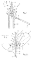
- a moving blade 1 according to the invention a turbomachine, in particular a turbine or a compressor Profile body 2, which is aerodynamically shaped and flows around in operation.
- Fig. 2 is a tip profile formed at the tip of the profile body 2 by a dashed line shown and labeled 3.
- One at the radially inside lying foot of the profile body present foot profile is designated 4. How emerges from the profile course along the profile body 2, this is wound.
- the radial direction is in FIG. 1 by an arrow 7 symbolizes.
- the projecting regions of the cover tape 5 are 9 and 10 in FIG. 2 denotes and serve in the operation of the blade 1 for flow guidance, by hindering an undesired flow around the profile body 2.
- these areas 9, 10 of the shroud 5 are dimensioned such that that they operate with corresponding areas 9, 10 in the operation of the rotor blade 1 Adjacent blades 1 for stabilizing the blades 1 interact.
- the cover bands 5 Adjacent blades 1 on the protruding in the circumferential direction Areas 9, 10 next to one another, for which purpose corresponding contact surfaces 11 are formed on the areas 9, 10. This will on the one hand limited additional torsion of the profile body 2 in operation. on the other hand the mutual support dampens the formation of vibrations or increases their frequency.
- the cover tape 5 is in operation in its cantilevered areas 9,10 not deformed in an inadmissible manner, is a fin radially outside on the shroud 5 12 molded.
- This fin 12 extends in the circumferential direction 6 along the Cover tape 5, centered on the profile body 2 over the entire extent of the Shroud 5, also in the projecting areas 9, 10.
- a T-beam profile is formed in the region of the fin 12 on the shroud 5, the can be seen in Fig. 1.
- the fin 12 thus results in an intense Stiffening of the cantilevered areas 9, 10, as a result of which the cover tape 5 is a receives sufficient stability.
- the fin 12 has one in FIG curly bracket marked area 13 in which the profile body 2 the cover tape 5 connects, a base section 14, which in the cover tape 5th transforms.
- This base section 14 closes according to FIG. 1 in the radial direction 7 and, according to FIG. 2, a transition section 15 in the circumferential direction 6.
- On this transition section 15 closes again according to FIG. 1 in the radial direction 7 and, according to FIG. 2, a sealing section 16 in the circumferential direction 6.
- the fin 12 realizes its sealing function by they flow radially around the shroud 5 in the axial direction on the outside.
- Indentation 17 is formed, which is the wall thickness of the base section 14 locally reduced.
- the two recesses 17 are there with respect to one another in the circumferential direction 6 and in the radial direction 7 extending unspecified plane of the fin 12 each other arranged opposite each other.
- the depressions 17 are each designed so that they have an opening cross section lying parallel to the plane of the fin 12 have, which is indicated in the figures by an arrow 20 and in axial direction 8 with respect to the fin 12 extended outwards.
- the depressions 17 can be frustoconical. This geometric shape of the depressions 17 serves to optimize the Stress distribution in the fin 12 during operation and facilitates demolding of the model.
- Each of the depressions 17 has a flat bottom 18. These floors 18 delimit a wall section 19 which is formed by molding the recesses 17 remains and has a smaller wall thickness than the rest of the area Base section 14 or as the transition region 15 Bottoms 18 of the depressions 17 run essentially parallel to Sealing section 16 of the fin 12, that is to say essentially parallel to the radial one Direction 7 and parallel to the circumferential direction 6.
- the embodiment shows the wall thickness of the base section 14 in the region of the Wells 17, so reduced in the wall section 19 to the extent that essentially corresponds to the wall thickness of the sealing section 16.
- the same Wall thicknesses are indicated in FIGS. 1 and 2 by dimension arrows and labeled D.
- the two depressions 17 are expediently designed to be symmetrical to such an extent that that the remaining between the recesses 17 wall portion 19 with the Sealing section 16 of the fin 12 according to FIG. 1 in the radial direction 7 and 2 aligned in the circumferential direction 6. This measure also leads to a Optimization with regard to the stress distribution in the fin 12 and its Resilience.
- the one when casting the blade 1, the fin 12 in the base section 14 can cool down faster and less during the solidification process flowing melt needed to avoid shrinking.
- the formation of porous structures can be reduced or avoided.
- the Strength and the service life of the blade 1 are thus increased.
- the weight of the fin 12 can be reduced by this measure, so as to reduce the load on the blade 1 during operation.
- the positioning and the geometric shape as well as the number of Wells 17 are appropriately chosen so that for Stiffening function and sealing function of the fin 12 on the one hand and the Manufacture and durability of the blade 1 on the other hand Optimal results.
Landscapes
- Engineering & Computer Science (AREA)
- Mechanical Engineering (AREA)
- General Engineering & Computer Science (AREA)
- Structures Of Non-Positive Displacement Pumps (AREA)
- Turbine Rotor Nozzle Sealing (AREA)
Abstract
Zur Vermeidung einer porösen Struktur im Basisabschnitt (14) sind an der Außenseite des Basisabschnitts (14) zwei Vertiefungen (17) eingeformt, welche die Wanddicke des Basisabschnitts (14) reduzieren.
Description
- Fig. 1
- einen axialen Schnitt durch eine Laufschaufel nach der Erfindung im Bereich einer Finne entsprechend den Schnittlinien I in Fig. 2,
- Fig. 2
- einen Schnitt in Umfangsrichtung durch die Finne entsprechend den Schnittlinien II in Fig. 1.
- 1
- Laufschaufel
- 2
- Profilkörper
- 3
- Spitzenprofil von 2
- 4
- Fußprofil von 2
- 5
- Deckband
- 6
- Umfangsrichtung
- 7
- radiale Richtung
- 8
- axiale Richtung
- 9
- auskragender Bereich von 5
- 10
- auskragender Bereich von 5
- 11
- Kontaktfläche
- 12
- Finne
- 13
- Bereich von 12
- 14
- Basisabschnitt von 12
- 15
- Übergangsabschnitt 12
- 16
- Dichtungsabschnitt von 12
- 17
- Vertiefung in 14
- 18
- Boden von 17
- 19
- Wandabschnitt
Claims (8)
- Einstückig gegossene Laufschaufel für eine Turbomaschine, insbesondere Turbine oder Verdichter,mit einem aerodynamisch geformten Profilkörper (2), der an seinem radial außen liegenden Ende ein angeformtes Deckband (5) aufweist, das in Umfangsrichtung (6) über den Profilkörper (2) auskragt und radial außen eine angeformte Finne (12) aufweist, die sich in Umfangsrichtung (6) entlang des Deckbands (5) erstreckt und die zumindest in einem Bereich (13) des Deckbands (5), in dem der Profilkörper (2) verläuft, einen mit dem Deckband (5) verbundenen Basisabschnitt (14), einen radial und/oder in Umfangsrichtung (6) an den Basisabschnitt (14) anschließenden Übergangsabschnitt (15) sowie einen radial und/oder in Umfangsrichtung (6) an den Übergangsabschnitt (15) anschließenden Dichtungsabschnitt (16) aufweist,wobei eine axial gemessene Wanddicke im Übergangsabschnitt (15) vom Basisabschnitt (14) zum Dichtungsabschnitt (16) abnimmt,wobei wenigstens eine die Wanddicke des Basisabschnitts (14) reduzierende Vertiefung (17) außen am Basisabschnitt (14) eingeformt ist.
- Laufschaufel nach Anspruch 1,
dadurch gekennzeichnet, dass wenigstens zwei Vertiefungen (17) vorgesehen sind, die bezüglich einer sich in Umfangsrichtung (6) und radial erstreckenden Ebene einander gegenüberliegend angeordnet sind. - Laufschaufel nach Anspruch 2,
dadurch gekennzeichnet, dass ein zwischen den gegenüberliegenden Vertiefungen (17) verbleibender Wandabschnitt (19) mit dem Dichtungsabschnitt (16) der Finne (12) fluchtet. - Laufschaufel nach Anspruch 2 oder 3,
dadurch gekennzeichnet, dass ein zwischen den gegenüberliegenden Vertiefungen (17) verbleibender Wandabschnitt (19) im wesentlichen dieselbe Wanddicke (D) aufweist wie der Dichtungsabschnitt (16) der Finne (12). - Laufschaufel nach einem der Ansprüche 1 bis 4,
dadurch gekennzeichnet, dass im Bereich der Vertiefung (17) oder der Vertiefungen (17) die Wanddicke (D) des Basisabschnitts (14) im wesentlichen der Wanddicke (D) des Dichtungsabschnitts (16) entspricht. - Laufschaufel nach einem der Ansprüche 1 bis 5,
dadurch gekennzeichnet, dass die Vertiefung (17) einen ebenen Boden (18) aufweist, der sich im wesentlichen parallel zum Dichtungsabschnitt (16) erstreckt. - Laufschaufel nach einem der Ansprüche 1 bis 6,
dadurch gekennzeichnet, dass die Vertiefung (17) im wesentlichen kegelstumpfförmig ausgebildet ist. - Laufschaufel nach einem der Ansprüche 1 bis 7,
dadurch gekennzeichnet, dass die Vertiefung (17) einen sich in axialer Richtung (8) nach außen hin erweiternden Öffnungsquerschnitt (20) aufweist, der parallel zu einer sich in Umfangsrichtung (6) und in radialer Richtung (7) erstreckenden Ebene der Finne (12) verläuft.
Applications Claiming Priority (2)
| Application Number | Priority Date | Filing Date | Title |
|---|---|---|---|
| CH6362002 | 2002-04-16 | ||
| CH6362002 | 2002-04-16 |
Publications (2)
| Publication Number | Publication Date |
|---|---|
| EP1355043A1 true EP1355043A1 (de) | 2003-10-22 |
| EP1355043B1 EP1355043B1 (de) | 2006-07-26 |
Family
ID=28458275
Family Applications (1)
| Application Number | Title | Priority Date | Filing Date |
|---|---|---|---|
| EP03100770A Expired - Lifetime EP1355043B1 (de) | 2002-04-16 | 2003-03-25 | Laufschaufel für eine Turbomaschine |
Country Status (4)
| Country | Link |
|---|---|
| US (1) | US6962484B2 (de) |
| EP (1) | EP1355043B1 (de) |
| JP (1) | JP2003314201A (de) |
| DE (1) | DE50304325D1 (de) |
Cited By (1)
| Publication number | Priority date | Publication date | Assignee | Title |
|---|---|---|---|---|
| WO2008097287A3 (en) * | 2006-12-15 | 2008-12-24 | Siemens Energy Inc | Aero-mixing of rotating blade structures |
Families Citing this family (33)
| Publication number | Priority date | Publication date | Assignee | Title |
|---|---|---|---|---|
| US7255531B2 (en) * | 2003-12-17 | 2007-08-14 | Watson Cogeneration Company | Gas turbine tip shroud rails |
| JP2005214205A (ja) * | 2004-01-31 | 2005-08-11 | United Technol Corp <Utc> | 回転機械用のロータブレード |
| DE102004025321A1 (de) * | 2004-05-19 | 2005-12-08 | Alstom Technology Ltd | Strömungsmaschinenschaufel |
| JP5228311B2 (ja) * | 2006-11-08 | 2013-07-03 | 株式会社Ihi | 圧縮機静翼 |
| US8257035B2 (en) * | 2007-12-05 | 2012-09-04 | Siemens Energy, Inc. | Turbine vane for a gas turbine engine |
| EP2385215A1 (de) * | 2010-05-05 | 2011-11-09 | Alstom Technology Ltd | Leichte Deckband-Dichtrippe für eine Rotorschaufel |
| US9151166B2 (en) | 2010-06-07 | 2015-10-06 | Rolls-Royce North American Technologies, Inc. | Composite gas turbine engine component |
| WO2014189875A1 (en) * | 2013-05-21 | 2014-11-27 | Siemens Energy, Inc. | Turbine blade tip shroud |
| US9464530B2 (en) * | 2014-02-20 | 2016-10-11 | General Electric Company | Turbine bucket and method for balancing a tip shroud of a turbine bucket |
| US9650914B2 (en) | 2014-02-28 | 2017-05-16 | Pratt & Whitney Canada Corp. | Turbine blade for a gas turbine engine |
| EP2924240A1 (de) * | 2014-03-25 | 2015-09-30 | Siemens Aktiengesellschaft | Turbinenlaufschaufel |
| US20180230819A1 (en) * | 2017-02-14 | 2018-08-16 | General Electric Company | Turbine blade having tip shroud rail features |
| US10696906B2 (en) | 2017-09-29 | 2020-06-30 | Marathon Petroleum Company Lp | Tower bottoms coke catching device |
| DE102018210513A1 (de) | 2018-06-27 | 2020-01-02 | MTU Aero Engines AG | Rotor für eine Strömungsmaschine und Strömungsmaschine mit einem solchen Rotor |
| US12000720B2 (en) | 2018-09-10 | 2024-06-04 | Marathon Petroleum Company Lp | Product inventory monitoring |
| US12031676B2 (en) | 2019-03-25 | 2024-07-09 | Marathon Petroleum Company Lp | Insulation securement system and associated methods |
| US11975316B2 (en) | 2019-05-09 | 2024-05-07 | Marathon Petroleum Company Lp | Methods and reforming systems for re-dispersing platinum on reforming catalyst |
| CA3212045A1 (en) | 2019-05-30 | 2020-11-30 | Marathon Petroleum Company Lp | Methods and systems for minimizing nox and co emissions in natural draft heaters |
| JP2021110291A (ja) * | 2020-01-10 | 2021-08-02 | 三菱重工業株式会社 | 動翼、及び軸流回転機械 |
| CA3109606C (en) | 2020-02-19 | 2022-12-06 | Marathon Petroleum Company Lp | Low sulfur fuel oil blends for paraffinic resid stability and associated methods |
| US12461022B2 (en) | 2021-02-25 | 2025-11-04 | Marathon Petroleum Company Lp | Methods and assemblies for determining and using standardized spectral responses for calibration of spectroscopic analyzers |
| US11898109B2 (en) | 2021-02-25 | 2024-02-13 | Marathon Petroleum Company Lp | Assemblies and methods for enhancing control of hydrotreating and fluid catalytic cracking (FCC) processes using spectroscopic analyzers |
| US11905468B2 (en) | 2021-02-25 | 2024-02-20 | Marathon Petroleum Company Lp | Assemblies and methods for enhancing control of fluid catalytic cracking (FCC) processes using spectroscopic analyzers |
| US11702600B2 (en) | 2021-02-25 | 2023-07-18 | Marathon Petroleum Company Lp | Assemblies and methods for enhancing fluid catalytic cracking (FCC) processes during the FCC process using spectroscopic analyzers |
| US12473500B2 (en) | 2021-02-25 | 2025-11-18 | Marathon Petroleum Company Lp | Assemblies and methods for enhancing control of fluid catalytic cracking (FCC) processes using spectroscopic analyzers |
| US20250012744A1 (en) | 2021-02-25 | 2025-01-09 | Marathon Petroleum Company Lp | Methods and assemblies for enhancing control of refining processes using spectroscopic analyzers |
| US11692141B2 (en) | 2021-10-10 | 2023-07-04 | Marathon Petroleum Company Lp | Methods and systems for enhancing processing of hydrocarbons in a fluid catalytic cracking unit using a renewable additive |
| US11802257B2 (en) | 2022-01-31 | 2023-10-31 | Marathon Petroleum Company Lp | Systems and methods for reducing rendered fats pour point |
| US12311305B2 (en) | 2022-12-08 | 2025-05-27 | Marathon Petroleum Company Lp | Removable flue gas strainer and associated methods |
| US12306076B2 (en) | 2023-05-12 | 2025-05-20 | Marathon Petroleum Company Lp | Systems, apparatuses, and methods for sample cylinder inspection, pressurization, and sample disposal |
| US12533615B2 (en) | 2023-06-02 | 2026-01-27 | Marathon Petroleum Company Lp | Methods and systems for reducing contaminants in a feed stream |
| US12415962B2 (en) | 2023-11-10 | 2025-09-16 | Marathon Petroleum Company Lp | Systems and methods for producing aviation fuel |
| US12599848B2 (en) | 2024-06-03 | 2026-04-14 | Marathon Petroleum Company Lp | Systems, analyzers, controllers, and associated methods to enhance fluid separation for distillation operations |
Citations (3)
| Publication number | Priority date | Publication date | Assignee | Title |
|---|---|---|---|---|
| JPH11350902A (ja) * | 1998-06-10 | 1999-12-21 | Ishikawajima Harima Heavy Ind Co Ltd | タービンの動翼 |
| US6241471B1 (en) * | 1999-08-26 | 2001-06-05 | General Electric Co. | Turbine bucket tip shroud reinforcement |
| JP2001193405A (ja) * | 2000-01-17 | 2001-07-17 | Mitsubishi Heavy Ind Ltd | シニング付チップシュラウド及びタービン設備 |
Family Cites Families (3)
| Publication number | Priority date | Publication date | Assignee | Title |
|---|---|---|---|---|
| US3867060A (en) * | 1973-09-27 | 1975-02-18 | Gen Electric | Shroud assembly |
| US4643645A (en) * | 1984-07-30 | 1987-02-17 | General Electric Company | Stage for a steam turbine |
| JPH10266804A (ja) * | 1997-03-26 | 1998-10-06 | Mitsubishi Heavy Ind Ltd | チップシュラウド翼キャビティ |
-
2003
- 2003-03-25 EP EP03100770A patent/EP1355043B1/de not_active Expired - Lifetime
- 2003-03-25 DE DE50304325T patent/DE50304325D1/de not_active Expired - Lifetime
- 2003-04-07 US US10/407,251 patent/US6962484B2/en not_active Expired - Fee Related
- 2003-04-15 JP JP2003110200A patent/JP2003314201A/ja not_active Withdrawn
Patent Citations (3)
| Publication number | Priority date | Publication date | Assignee | Title |
|---|---|---|---|---|
| JPH11350902A (ja) * | 1998-06-10 | 1999-12-21 | Ishikawajima Harima Heavy Ind Co Ltd | タービンの動翼 |
| US6241471B1 (en) * | 1999-08-26 | 2001-06-05 | General Electric Co. | Turbine bucket tip shroud reinforcement |
| JP2001193405A (ja) * | 2000-01-17 | 2001-07-17 | Mitsubishi Heavy Ind Ltd | シニング付チップシュラウド及びタービン設備 |
Non-Patent Citations (2)
| Title |
|---|
| PATENT ABSTRACTS OF JAPAN vol. 2000, no. 03 30 March 2000 (2000-03-30) * |
| PATENT ABSTRACTS OF JAPAN vol. 2000, no. 24 11 May 2001 (2001-05-11) * |
Cited By (2)
| Publication number | Priority date | Publication date | Assignee | Title |
|---|---|---|---|---|
| WO2008097287A3 (en) * | 2006-12-15 | 2008-12-24 | Siemens Energy Inc | Aero-mixing of rotating blade structures |
| US7753652B2 (en) | 2006-12-15 | 2010-07-13 | Siemens Energy, Inc. | Aero-mixing of rotating blade structures |
Also Published As
| Publication number | Publication date |
|---|---|
| US20030194322A1 (en) | 2003-10-16 |
| DE50304325D1 (de) | 2006-09-07 |
| JP2003314201A (ja) | 2003-11-06 |
| EP1355043B1 (de) | 2006-07-26 |
| US6962484B2 (en) | 2005-11-08 |
Similar Documents
| Publication | Publication Date | Title |
|---|---|---|
| EP1355043A1 (de) | Laufschaufel für eine Turbomaschine | |
| EP2017433B1 (de) | Gasturbinenschaufel mit modularem Aufbau | |
| EP0972128B1 (de) | Oberflächenstruktur für die wand eines strömungskanals oder einer turbinenschaufel | |
| DE69901608T2 (de) | Pelton turbinenlaufrad und peltonturbine mit einem solchen laufrad | |
| EP2576996B1 (de) | Abgasturbolader mit gleitlager zur verminderung von fluidwirbeln | |
| DE3223164C2 (de) | Turbomaschinenrotorbaugruppe und -laufschaufel | |
| DE69502988T2 (de) | Anordnung der Blaserschaufeln bei einem Gasturbinentriebwerk | |
| DE2558048A1 (de) | Einrichtung zum verschleissfesten abdecken der oberflaeche von schraubenfoermigen metallenen foerderschaufeln | |
| EP1707745A2 (de) | Laufschaufel für eine Strömungsmaschine sowie Strömungsmaschine | |
| DE102007002326A1 (de) | Turbinenschaufel- und Leitkranzkonstruktion | |
| EP3536974B1 (de) | Gasturbinenverdichter | |
| EP3176370A1 (de) | Leitschaufelcluster für eine strömungsmaschine | |
| DE60118863T2 (de) | Gaseinspritzsystem und Verfahren zur Herstellung eines solchen Systems | |
| EP1081336B1 (de) | Gebauter Leitkranz für eine Gasturbine | |
| DE2444478A1 (de) | Befestigungsanordnung fuer ein lager einer axialstroemungs-turbomaschine | |
| EP1636473B1 (de) | Kolben für einen verbrennungsmotor und giessverfahren zu dessen herstellung | |
| EP2994615B1 (de) | Rotor für eine thermische strömungsmaschine | |
| EP3704386B1 (de) | Generativ gefertigter zwischenkanal zur anordnung zwischen einem niederdruckverdichter und einem hochdruckverdichter, sowie entsprechendes fertigungsverfahren | |
| EP3425172A1 (de) | Dichtring für eine turbomaschine, turbomaschine mit einem solchen dichtring und verfahren zur herstellung eines solchen dichtrings | |
| WO2016134699A1 (de) | Radträger | |
| EP3293369B1 (de) | Verkleidungselement für ein turbinenzwischengehäuse | |
| EP1747349A1 (de) | STRÖMUNGSMASCHINENSCHAUFEL MIT EINEM DECKBAND UND GEWICHTSOéTIMIERTER DICHTLEISTE | |
| EP3527789A1 (de) | Lagerkammergehäuse für eine strömungsmaschine | |
| DE602004012805T2 (de) | Linearreibschweissverfahren von Schaufeln zu Integralrotorer und Schaufel mit einem Fuss, der einen reduzierten Flächesatz von weniger als 2 aufweist | |
| EP1355041B1 (de) | Turbinenschaufel |
Legal Events
| Date | Code | Title | Description |
|---|---|---|---|
| PUAI | Public reference made under article 153(3) epc to a published international application that has entered the european phase |
Free format text: ORIGINAL CODE: 0009012 |
|
| AK | Designated contracting states |
Kind code of ref document: A1 Designated state(s): AT BE BG CH CY CZ DE DK EE ES FI FR GB GR HU IE IT LI LU MC NL PT SE SI SK TR |
|
| AX | Request for extension of the european patent |
Extension state: AL LT LV MK |
|
| RAP1 | Party data changed (applicant data changed or rights of an application transferred) |
Owner name: ALSTOM TECHNOLOGY LTD |
|
| 17P | Request for examination filed |
Effective date: 20040410 |
|
| AKX | Designation fees paid |
Designated state(s): DE GB |
|
| 17Q | First examination report despatched |
Effective date: 20040820 |
|
| GRAP | Despatch of communication of intention to grant a patent |
Free format text: ORIGINAL CODE: EPIDOSNIGR1 |
|
| GRAS | Grant fee paid |
Free format text: ORIGINAL CODE: EPIDOSNIGR3 |
|
| GRAA | (expected) grant |
Free format text: ORIGINAL CODE: 0009210 |
|
| RIN1 | Information on inventor provided before grant (corrected) |
Inventor name: BRANDL, HERBERT Inventor name: HOFFS, ALEXANDER |
|
| AK | Designated contracting states |
Kind code of ref document: B1 Designated state(s): DE GB |
|
| REG | Reference to a national code |
Ref country code: GB Ref legal event code: FG4D Free format text: NOT ENGLISH |
|
| REF | Corresponds to: |
Ref document number: 50304325 Country of ref document: DE Date of ref document: 20060907 Kind code of ref document: P |
|
| GBT | Gb: translation of ep patent filed (gb section 77(6)(a)/1977) |
Effective date: 20060923 |
|
| PLBE | No opposition filed within time limit |
Free format text: ORIGINAL CODE: 0009261 |
|
| STAA | Information on the status of an ep patent application or granted ep patent |
Free format text: STATUS: NO OPPOSITION FILED WITHIN TIME LIMIT |
|
| 26N | No opposition filed |
Effective date: 20070427 |
|
| PGFP | Annual fee paid to national office [announced via postgrant information from national office to epo] |
Ref country code: GB Payment date: 20110221 Year of fee payment: 9 Ref country code: DE Payment date: 20110331 Year of fee payment: 9 |
|
| GBPC | Gb: european patent ceased through non-payment of renewal fee |
Effective date: 20120325 |
|
| REG | Reference to a national code |
Ref country code: DE Ref legal event code: R119 Ref document number: 50304325 Country of ref document: DE Effective date: 20121002 |
|
| PG25 | Lapsed in a contracting state [announced via postgrant information from national office to epo] |
Ref country code: GB Free format text: LAPSE BECAUSE OF NON-PAYMENT OF DUE FEES Effective date: 20120325 |
|
| PG25 | Lapsed in a contracting state [announced via postgrant information from national office to epo] |
Ref country code: DE Free format text: LAPSE BECAUSE OF NON-PAYMENT OF DUE FEES Effective date: 20121002 |