EP1354659A2 - Arc starting method between a workpiece and a consumable electrode - Google Patents
Arc starting method between a workpiece and a consumable electrode Download PDFInfo
- Publication number
- EP1354659A2 EP1354659A2 EP03010540A EP03010540A EP1354659A2 EP 1354659 A2 EP1354659 A2 EP 1354659A2 EP 03010540 A EP03010540 A EP 03010540A EP 03010540 A EP03010540 A EP 03010540A EP 1354659 A2 EP1354659 A2 EP 1354659A2
- Authority
- EP
- European Patent Office
- Prior art keywords
- current
- welding
- electrode
- workpiece
- arc
- Prior art date
- Legal status (The legal status is an assumption and is not a legal conclusion. Google has not performed a legal analysis and makes no representation as to the accuracy of the status listed.)
- Granted
Links
Images


Classifications
-
- B—PERFORMING OPERATIONS; TRANSPORTING
- B23—MACHINE TOOLS; METAL-WORKING NOT OTHERWISE PROVIDED FOR
- B23K—SOLDERING OR UNSOLDERING; WELDING; CLADDING OR PLATING BY SOLDERING OR WELDING; CUTTING BY APPLYING HEAT LOCALLY, e.g. FLAME CUTTING; WORKING BY LASER BEAM
- B23K9/00—Arc welding or cutting
- B23K9/06—Arrangements or circuits for starting the arc, e.g. by generating ignition voltage, or for stabilising the arc
- B23K9/067—Starting the arc
- B23K9/0672—Starting the arc without direct contact between electrodes
-
- B—PERFORMING OPERATIONS; TRANSPORTING
- B23—MACHINE TOOLS; METAL-WORKING NOT OTHERWISE PROVIDED FOR
- B23K—SOLDERING OR UNSOLDERING; WELDING; CLADDING OR PLATING BY SOLDERING OR WELDING; CUTTING BY APPLYING HEAT LOCALLY, e.g. FLAME CUTTING; WORKING BY LASER BEAM
- B23K9/00—Arc welding or cutting
- B23K9/06—Arrangements or circuits for starting the arc, e.g. by generating ignition voltage, or for stabilising the arc
- B23K9/067—Starting the arc
- B23K9/0671—Starting the arc by means of brief contacts between the electrodes
-
- B—PERFORMING OPERATIONS; TRANSPORTING
- B23—MACHINE TOOLS; METAL-WORKING NOT OTHERWISE PROVIDED FOR
- B23K—SOLDERING OR UNSOLDERING; WELDING; CLADDING OR PLATING BY SOLDERING OR WELDING; CUTTING BY APPLYING HEAT LOCALLY, e.g. FLAME CUTTING; WORKING BY LASER BEAM
- B23K9/00—Arc welding or cutting
- B23K9/06—Arrangements or circuits for starting the arc, e.g. by generating ignition voltage, or for stabilising the arc
- B23K9/067—Starting the arc
- B23K9/0672—Starting the arc without direct contact between electrodes
- B23K9/0673—Ionisation of the arc gap by means of a tension with a step front (pulses or high frequency tensions)
Definitions
- This object of the invention is achieved by the procedure according to the ignition method an arc between a workpiece and a melting electrode, in particular a welding wire as described in the characterizing part of claim 1 is solved.
- Constant voltage source 32 is used for igniting the arc 16, being at a welding process after the ignition of the arc 16 the constant voltage source 32 is deactivated and the welding process is supplied with energy by the constant current source 3 becomes.
- this arc column in particular the arc 16 having a high current density and causes a high pressure between the welding wire end and the workpiece 17.
- the time period, especially the rate of current rise up to to reach the current value 43 depends on the open circuit voltage of the constant current source 3 as well as the arc voltage and the welding circuit inductance.
- the control device 5 uses a wire feed device 12 applied positive potential, so that the forward movement of the welding wire 14 is initiated becomes.
- the wire feed device 12 is now controlled such that the actual welding wire speed, which is necessary for the welding process becomes.
- the current from the value 65 to a predetermined value 69 lowered.
- the value 69 corresponds to the minimum value for supplying the arc 16, so that the arc 16 is prevented from being torn off.
- the constant voltage source 32 and the capacitor 74 also make it steeper Current increase to the maximum value 40 - Fig. 5 - achieved, then after reaching this maximum value 40 that of the constant voltage source 32, in particular the capacitor 74 emitted current drops and the arc 16 by the increasing current from the Constant current source 3 is maintained.
- the arc must first 16 are ignited. To do this, the user activates the welding device 1 so that all Components of the welding device 1, as described in Fig. 1, with current and voltage be supplied. After the user via the input and / or output device 22 the user has made all settings for a welding process, for example by activating a button arranged, for example, on the welding torch 11 is to start the welding process.
- the current from the constant current source 3 increases at a time 148 than that of the constant voltage source 132. This is possible because the user at the Activate or set a corresponding current value for the welding process so that due to the short circuit at time 144, the constant current source 3 the welding wire 14 want to supply with the preset current value, so that due to the lowering of the Current from the constant voltage source 132 and the current rise from the constant current source 3, for example from time 147, a supply of the welding wire 14 is created via the constant current source 3.
- 15 shows another embodiment of the welding current source 2 with the constant current source 3 and the constant voltage source 132, in which case the constant voltage source 132 is fed from the output of the constant current source 3.
Landscapes
- Engineering & Computer Science (AREA)
- Physics & Mathematics (AREA)
- Plasma & Fusion (AREA)
- Mechanical Engineering (AREA)
- Arc Welding Control (AREA)
- Electrical Discharge Machining, Electrochemical Machining, And Combined Machining (AREA)
- Arc Welding In General (AREA)
- Discharge Heating (AREA)
Abstract
Description
Die Erfindung betrifft ein Verfahren zum Zünden eines Lichtbogens zwischen einem Werkstück
und einer abschmelzenden Elektrode, wie dieses im Oberbegriff des Anspruches 1 beschrieben
ist.The invention relates to a method for igniting an arc between a workpiece
and a melting electrode as described in the preamble of
Aus der DE 40 32 618 A1 ist ein Verfahren zum Zünden eines Lichtbogens nach dem Lift-Arc Prinzip bekannt, bei dem zum Zünden des Lichtbogens zwei Energiequellen parallel geschaltet sind. Dabei wird der Schweißdraht von einem Drahtvorschubgerät bis zum Berühren an das Werkstück zubewegt, wodurch ein Kurzschluss geschaffen wird. Anschließend wird der Schweißdraht durch die zusätzliche Energiequelle mit einer geringen Stromstärke vom Werkstück abgehoben bzw. zurückgezogen, sodass aufgrund der Aufhebung des Kurzschlusses eine Zündung des Lichtbogens erfolgt. Die Höhe des Stromes ist dabei so definiert, dass ein Abschmelzen des Materials vom Schweißdraht verhindert wird. Nach Ablauf einer voreinstellbaren Zeitdauer bzw. nach dem Zünden des Lichtbogens wird der Schweißdraht wiederum in Richtung des Werkstückes bewegt, wobei nunmehr die Versorgung des Lichtbogens mit einem hohen Strom über die primäre Energiequelle erfolgt, sodass ein Abschmelzen des Schweißdrahtes gewährleistet ist.DE 40 32 618 A1 describes a method for igniting an arc after the lift arc Known principle in which two energy sources are connected in parallel to ignite the arc are. The welding wire is moved from a wire feeder until it is touched moved towards the workpiece, creating a short circuit. Then will the welding wire through the additional energy source with a low current from Workpiece lifted or withdrawn, so that due to the cancellation of the short circuit the arc is ignited. The amount of current is defined so that melting of the material from the welding wire is prevented. After a pre-settable Time or after the arc is ignited, the welding wire in turn moved in the direction of the workpiece, now supplying the arc with a high current over the primary energy source, so that the melting Welding wire is guaranteed.
Weiters ist aus der DE 37 31 180 C2 ein Verfahren zum Zünden eines Lichtbogens bekannt,
bei dem die Versorgung des Lichtbogens bzw. die Zündung des Lichtbogens über eine geregelte
Energiequelle erfolgt. Hierzu wird der Schweißdraht in Richtung des Werkstückes
bewegt, sodass ein Kurzschluss zwischen dem Schweißdraht und dem Werkstück entsteht,
wobei gleichzeitig der Schweißdraht von der Energiequelle mit einem geringen Strom versorgt
wird, sodass bei der Bildung des Kurzschlusses der Lichtbogen durch Abschmelzen des
Schweißdrahtes mit einer geringen Lichtbogenlänge gezündet wird. Diese Energie bzw. die
Höhe des Stromes zum Zünden des Lichtbogens ist derartig ausgelegt, dass ein Aufschmelzen
bzw. Abschmelzen des Schweißdrahtes erfolgt. Anschließend wird mit wachsender Lichtbogenlänge
der Energiebedarf bzw. der Strom am Schweißdraht erhöht, sodass nach Erreichen
einer einstellbaren Schwelle ein definierter Energieimpuls bzw. Stromimpuls ausgesendet
wird, und somit ein Ablösen des Tropfens am Schweißdrahtende erzielt wird. Bei einem derartigen
Verfahren kann es zur Bildung satten Kurzschlusses kommen, d.h., dass bei Erlöschen
des Lichtbogens das aufgeschmolzene Material am dem Werkstück kleben bleibt, sodass dieser
satte Kurzschluss nurmehr mit einem extrem hohen Stromimpuls über eine gewisse Zeitdauer
behoben werden kann, wodurch Schweißspritzer und Einbrände neben der Schweißstelle
entstehen.Furthermore, a method for igniting an arc is known from
Der vorliegenden Erfindung liegt die Aufgabe zugrunde, ein Verfahren zum Zünden eines Lichtbogens zwischen einem Werkstück und einer abschmelzenden Elektrode, insbesondere einem Schweißdraht zu schaffen, bei der eine sichere und stabile Zündung des Lichtbogens erreicht wird.The present invention has for its object a method for igniting a Arc between a workpiece and a melting electrode, in particular to create a welding wire in which a safe and stable ignition of the arc is achieved.
Diese Aufgabe der Erfindung wird durch die Vorgehensweise nach dem Verfahren zum Zünden
eines Lichtbogens zwischen einem Werkstück und einer abschmelzenden Elektrode, insbesondere
einem Schweißdraht, wie dieses im kennzeichnenden Teil des Anspruches 1 beschrieben
ist, gelöst.This object of the invention is achieved by the procedure according to the ignition method
an arc between a workpiece and a melting electrode, in particular
a welding wire as described in the characterizing part of
Vorteilhaft ist hierbei, dass durch die stufenweise Anhebung des Stromes eine Vorwärmphase für den Schweißdraht geschaffen wird, sodass durch Aufhebung des Kurzschlusses, also nachdem nach Abheben des Schweißdrahtes vom Werkstück, eine sichere Zündung erreicht wird. Ein weiterer Vorteil liegt darin, dass nach dem Zünden des Lichtbogens der Strom auf einen voreinstellbaren Wert erhöht wird, wodurch ein kontrolliertes Abschmelzen des Schweißdrahtes erreicht wird und dass so erst bei Erreichen einer bestimmten Lichtbogenlänge, die über die Lichtbogenspannung erfasst wird, der tatsächliche Schweißprozess freigegeben wird, wodurch ein Abreißen bzw. Erlöschen des Lichtbogens bei zu frühem Start des tatsächlichen Schweißprozesses verhindert werden kann.It is advantageous here that a preheating phase is achieved by gradually increasing the current is created for the welding wire, so that by removing the short circuit, i.e. after after lifting the welding wire from the workpiece, a reliable ignition is achieved. Another advantage is that after the arc is ignited, the current is on you preset value is increased, which leads to a controlled melting of the welding wire is achieved and that only when a certain arc length is reached, which over the arc voltage is sensed, thereby releasing the actual welding process the arc is broken or extinguished if the actual start is too early Welding process can be prevented.
Weitere vorteilhafte Maßnahmen sind in den Ansprüchen 2 bis 6 beschrieben. Die damit erzielbaren
Vorteile sind der detaillierten Figurenbeschreibung zu entnehmen.Further advantageous measures are described in
Die Erfindung wird im nachfolgenden anhand der in den Zeichnungen dargestellten Ausführungsbeispiele näher erläutert.The invention is described below with reference to the exemplary embodiments shown in the drawings explained in more detail.
Es zeigen:
- Fig. 1
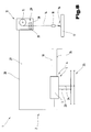
- eine schematische Darstellung eines Schweißgerätes mit den einzelnen Komponenten in vereinfachter, schematischer Darstellung;
- Fig. 2
- ein Blockschaltbild der Schweißstromquelle mit parallel geschalteter Spannungsquelle in vereinfachter und schematischer Darstellung;
- Fig. 3
- einen Vorschubgeschwindigkeitsverlauf für ein Drahtvorschubgerät in vereinfachter und schematischer Darstellung für das Ausführungsbeispiel nach Fig. 2;
- Fig. 4
- einen Spannungsverlauf am Schweißdraht in vereinfachter, schematischer Darstellung für das Ausführungsbeispiel nach Fig. 2;
- Fig. 5
- einen Stromverlauf am Schweißdraht in vereinfachter, schematischer Darstellung für das Ausführungsbeispiel nach Fig. 2;
- Fig. 6
- ein Blockschaltbild für die Schweißstromquelle in vereinfachter, schematischer Darstellung;
- Fig. 7
- einen Vorschubgeschwindigkeits- und Richtungsverlauf für das Drahtvorschubgerät nach Fig. 6, in vereinfachter, schematischer Darstellung;
- Fig. 8
- einen Spannungsverlauf am Schweißdraht für das Ausführungsbeispiel nach Fig. 6, in vereinfachter, schematischer Darstellung;
- Fig. 9
- einen Stromverlauf am Schweißdraht für das Ausführungsbeispiel nach Fig. 6, in vereinfachter, schematischer Darstellung;
- Fig. 10
- ein Blockschaltbild eines weiteren Ausführungsbeispiels der Schweißstromquelle gemäß Fig. 2 zur Erzielung des erfindungsgemäßen Verfahrensablaufes gemäß den Fig. 3 bis 5;
- Fig. 11
- ein Blockschaltbild der Schweißstromquelle mit der Konstant-Stromquelle und der erfindungsgemäß parallel geschalteten Konstant-Spannungsquelle in vereinfachter und schematischer Darstellung;
- Fig. 12
- einen Vorschubgeschwindigkeitsverlauf für ein Drahtvorschubgerät in vereinfachter und schematischer Darstellung für das Ausführungsbeispiel nach Fig. 11;
- Fig. 13
- einen Spannungsverlauf am Schweißdraht in vereinfachter, schematischer Darstellung für das Ausführungsbeispiel nach Fig. 11;
- Fig. 14
- einen Stromverlauf am Schweißdraht in vereinfachter, schematischer Darstellung für das Ausführungsbeispiel nach Fig. 11;
- Fig. 15
- ein Blockschaltbild eines weiteren Ausführungsbeispiels der Schweißstromquelle gemäß Fig. 11 zur Erzielung des erfindungsgemäßen Verfahrensablaufes gemäß den Fig. 12 bis 14.
- Fig. 1
- a schematic representation of a welding device with the individual components in a simplified, schematic representation;
- Fig. 2
- a block diagram of the welding current source with a voltage source connected in parallel in a simplified and schematic representation;
- Fig. 3
- a feed speed curve for a wire feed device in a simplified and schematic representation for the embodiment of FIG. 2;
- Fig. 4
- a voltage curve on the welding wire in a simplified, schematic representation for the embodiment of FIG. 2;
- Fig. 5
- a current profile on the welding wire in a simplified, schematic representation for the embodiment of FIG. 2;
- Fig. 6
- a block diagram for the welding power source in a simplified, schematic representation;
- Fig. 7
- a feed speed and direction course for the wire feed device of Figure 6, in a simplified, schematic representation.
- Fig. 8
- a voltage curve on the welding wire for the embodiment of FIG. 6, in a simplified, schematic representation;
- Fig. 9
- a current profile on the welding wire for the embodiment of FIG. 6, in a simplified, schematic representation;
- Fig. 10
- 3 shows a block diagram of a further exemplary embodiment of the welding current source according to FIG. 2 for achieving the method sequence according to the invention according to FIGS. 3 to 5;
- Fig. 11
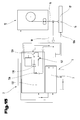
- a block diagram of the welding current source with the constant current source and the constant voltage source connected in parallel according to the invention in a simplified and schematic representation;
- Fig. 12
- a feed rate curve for a wire feed device in a simplified and schematic representation for the embodiment of FIG. 11;
- Fig. 13
- a voltage curve on the welding wire in a simplified, schematic representation for the embodiment of FIG. 11;
- Fig. 14
- a current profile on the welding wire in a simplified, schematic representation for the embodiment of FIG. 11;
- Fig. 15
- 11 shows a block diagram of a further exemplary embodiment of the welding current source according to FIG. 11 to achieve the method sequence according to the invention according to FIGS. 12 to 14.
Einführend sei festgehalten, dass in den unterschiedlich beschriebenen Ausführungsformen gleiche Teile bzw. Zustände mit gleichen Bezugszeichen bzw. gleichen Bauteilbezeichnungen versehen werden, wobei die in der gesamten Beschreibung enthaltenen Offenbarungen sinngemäß auf gleiche Teile bzw. Zustände mit gleichen Bezugszeichen bzw. gleichen Bauteilbezeichnungen übertragen werden können. Weiters können auch Einzelmerkmale aus den gezeigten unterschiedlichen Ausführungsbeispielen für sich eigenständige, erfindungsgemäße Lösungen darstellen.In the introduction it should be noted that in the differently described embodiments same parts or states with the same reference numerals or same component names are provided, with the disclosures contained throughout the description analogous to the same parts or states with the same reference symbols or the same component designations can be transferred. Furthermore, individual features from the shown different embodiments for themselves, inventive Represent solutions.
In Fig. 1 is ein Schweißgerät 1, insbesondere eine Schweißstromquelle 2, für verschiedenste
Schweißverfahren, wie z.B. zum MIG-/MAG-Schweißen bzw. TIG-Schweißen gezeigt. Das
Schweißgerät 1, insbesondere die Schweißstromquelle 2, umfasst eine Konstant-Stromquelle
3 mit einem Leistungsteil 4, eine Steuervorrichtung 5 und ein dem Leistungsteil 4 bzw. der
Steuervorrichtung 5 zugeordnetes Umschaltglied 6. Das Umschaltglied 6 bzw. die Steuervorrichtung
5 ist mit einem Steuerventil 7 verbunden, welches in einer Versorgungsleitung 8 für
ein Gas 9, insbesondere ein Schutzgas, wie beispielsweise Stickstoff, Helium oder Argon und
dergleichen, zwischen einem Gasspeicher 10 und einem Schweißbrenner 11 angeordnet ist.In Fig. 1 is a
Zudem wird über die Steuervorrichtung 5 auch noch ein Drahtvorschubgerät 12 angesteuert,
wobei über eine Versorgungsleitung 13 ein Schweißdraht 14 von einer Vorratstrommel 15 in
den Bereich des Schweißbrenners 11 zugeführt wird. Die Energie zum Aufbau eines Lichtbogens
16 zwischen dem Schweißdraht 14 und einem Werkstück 17 wird über eine Versorgungsleitung
18 vom Leistungsteil 4 der Konstant-Stromquelle 3 dem Schweißbrenner 11
bzw. dem Schweißdraht 14 zugeführt. In addition, a
Zum Kühlen des Schweißbrenners 11 wird über einen Kühlkreislauf 19 der Schweißbrenner
11 unter Zwischenschaltung eines Strömungswächters 20 mit einem Wasserbehälter 21 verbunden,
sodass bei der Inbetriebnahme des Schweißbrenners 11 der Kühlkreislauf 19 von der
Steuervorrichtung 5 gestartet werden kann, wodurch eine Kühlung des Schweißbrenners 11
erreicht wird.To cool the
Weiters weist das Schweißgerät 1 eine Ein- und/oder Ausgabevorrichtung 22, wie z.B. Bedienelemente,
eine Tastatur und/oder ein Display auf, durch die die unterschiedlichsten
Schweißparameter bzw. Betriebsarten des Schweißgerätes 1 eingestellt werden können. Dabei
werden die über die Ein- und/oder Ausgabevorrichtung 22 eingestellten bzw. ausgewählten
Werte an die Steuervorrichtung 5 weitergeleitet, sodass anschließend von der Steuervorrichtung
5 die einzelnen Komponenten entsprechend den vorgegebenen Werten bzw. den aus diesen
Werten ermittelten Steuerfunktionen aktiviert werden können.Furthermore, the
In den Fig. 2 bis 5 ist ein Verfahrensablauf zum Zünden des Lichtbogens 16 zwischen dem
Werkstück 17 und einer abschmelzenden Elektrode, insbesondere dem Schweißdraht 14, gezeigt,
wobei in Fig. 2 ein vereinfachtes Blockschaltbild der Schweißstromquelle 2, insbesondere
des Schweißgerätes 1, dargestellt ist. Bei diesem Blockschaltbild sind in der Konstant-Stromquelle
3 die Komponenten des Leistungsteil 4 und der Steuervorrichtung 5, wie sie in
Fig. 1 beschrieben sind, integriert.2 to 5 is a process sequence for igniting the
Bei dem dargestellten Blockschaltbild sind die weiteren in Fig. 1 beschriebenen Komponenten
mit der Konstant-Stromquelle 3 leitungsverbunden, sodass eine Aktivierung, beispielsweise
des Kühlkreislaufes 19, durch die Konstant-Stromquelle 3, insbesondere der Steuervorrichtung
5, möglich ist. In Fig. 2 sind nur die für das Zünden des Lichtbogens 16 notwendigen
Komponenten dargestellt. Dazu ist die Konstant-Stromquelle 3 über Versorgungsleitungen
23, 24 mit einem Spannungsversorgungsnetz 25 verbunden, sodass die einzelnen Komponenten
des Schweißgerätes 1 mit Strom und Spannung versorgt werden können.In the block diagram shown, the other components described in FIG. 1 are
connected to the constant
In den Fig. 3 bis 5 sind in Form von Diagrammen Verfahrensabläufe dargestellt, wobei in den Fig. 4 und 5 auf der Ordinate die Spannung U bzw. der Strom I sowie auf der Abszisse die Zeit t aufgetragen sind.3 to 5 process sequences are shown in the form of diagrams, wherein in the 4 and 5 on the ordinate the voltage U and the current I and on the abscissa Time t are plotted.
Bei dem dargestellten Blockschaltbild in Fig. 2 ist die Konstant-Stromquelle 3 über die Versorgungsleitung
18 mit dem schematisch dargestellten Schweißbrenner 11 verbunden, wogegen
das Werkstück 17 über eine weitere Versorgungsleitung 26 mit der Konstant-Stromquelle
3 verbunden ist. Bei dem dargestellten Ausführungsbeispiel wird der Schweißbrenner 11 über
die Versorgungsleitung 18 mit dem positiven Potential versorgt, wogegen das negative Potential
über die Versorgungsleitung 26 am Werkstück 17 angelegt ist. Gleichzeitig weist die Konstant-Stromquelle
3 Steuerleitungen 27, 28 auf, die mit dem Drahtvorschubgerät 12 verbunden
sind. Bei dem Drahtvorschubgerät 12 sind die Vorratstrommel 15 sowie eine Fördervorrichtung
29 zum Befördern des Schweißdrahtes 14 an den Schweißbrenner 11 dargestellt. Die
Fördervorrichtung 29 kann aus zwei Förderrollen 30, 31 gebildet werden, wobei zumindest
eine der beiden Förderrollen 30, 31 über einen nicht dargestellten Motor angetrieben wird.In the block diagram shown in FIG. 2, the constant
Weiters ist in Fig. 2 eine zusätzliche Konstant-Spannungsquelle 32 parallel zur Konstant-Stromquelle
3 geschaltet, d.h., dass die Ausgänge der Konstant-Spannungsquelle 32 über
Leitungen 33, 34 mit den Versorgungsleitungen 18, 26 bzw. den Ausgängen der Konstant-Stromquelle
3 verbunden sind. Dabei ist das positive Potential der Konstant-Spannungsquelle
32 wiederum mit dem positiven Potential der Konstant-Stromquelle 3 zusammengeschaltet.
Damit die Konstant-Spannungsquelle 32 von der Steuervorrichtung 5 angesteuert werden
kann, ist eine Steuerleitung 35 zwischen der Steuervorrichtung 5, insbesondere der Konstant-Stromquelle
3 und der Konstant-Spannungsquelle 32 dargestellt.2 is an additional
Die Konstant-Spannungsquelle 32 ist derartig ausgebildet, dass sie den Schweißbrenner 11
mit einer sehr hohen Leerlaufspannung, beispielsweise zwischen 200 V und 500 V, versorgt.
Die Konstant-Stromquelle 3 versorgt den Schweißbrenner 11 mit dem Schweißstrom, der
beispielsweise zwischen 20 A und 500 A liegen kann.The
Es kann nunmehr gesagt werden, dass die zusätzlich angeordnete und parallel geschaltete
Konstant-Spannungsquelle 32 für das Zünden des Lichtbogens 16 verwendet wird, wobei bei
einem Schweißprozess nach dem Zünden des Lichtbogens 16 die Konstant-Spannungsquelle
32 deaktiviert ist und der Schweißprozess von der Konstant-Stromquelle 3 mit Energie versorgt
wird.It can now be said that the additionally arranged and connected in parallel
Bei den Diagrammen, wie sie in den Fig. 3 bis 5 dargestellt sind, ist ein Kurvenverlauf für die
Drahtvorschubgeschwindigkeit des Drahtvorschubgerätes 12 - Fig. 3 - und ein Spannungsverlauf
- Fig. 4 - sowie Stromverlauf - Fig. 5 - an der abschmelzenden Elektrode, insbesondere
am Schweißdraht 14 dargestellt. In the diagrams, as shown in FIGS. 3 to 5, there is a curve for the
Wire feed speed of the wire feed device 12 - FIG. 3 - and a voltage curve
- Fig. 4 - and current flow - Fig. 5 - on the melting electrode, in particular
shown on the
Möchte nunmehr ein Benutzer einen Schweißprozess durchführen, so muss zuerst der Lichtbogen
16 gezündet werden. Dazu aktiviert der Benutzer das Schweißgerät 1, sodass alle
Komponenten des Schweißgerätes 1, wie sie in Fig. 1 beschrieben sind, mit Strom und Spannung
versorgt werden. Nachdem der Benutzer über die Ein- und/oder Ausgabevorrichtung 22
alle Einstellungen für einen Schweißprozess vorgenommen hat, kann der Benutzer beispielsweise
durch Aktivieren eines Tasters, der beispielsweise am Schweißbrenner 11 angeordnet
ist, den Schweißprozess starten.If a user now wants to carry out a welding process, the arc must first
16 are ignited. To do this, the user activates the
Nach dem Starten des Schweißprozesses wird von der Steuervorrichtung 5 die Konstant-Stromquelle
3, insbesondere das Leistungsteil 4 und die Konstant-Spannungsquelle 32, aktiviert,
d.h., dass die Konstant-Stromquelle 3 und gleichzeitig die Konstant-Spannungsquelle 32
den Schweißbrenner 11 mit Energie versorgt. Am Schweißbrenner 11 wird die über die beiden
Energiequellen, insbesondere über die Konstant-Spannungsquelle 32 und die Konstant-Stromquelle
3 zugeführte Energie an den Schweißdraht 14 übergeben. Das Starten des
Schweißprozesses ist aus den Diagrammen der Fig. 3 bis 5 zum Zeitpunkt 36 dargestellt. Wie
nun aus den beiden Kurvenverläufen der Fig. 4 und 5 zu ersehen ist, wird der Schweißdraht
14 von der Konstant-Spannungsquelle 32 mit einer sehr hohen Gleichspannung versorgt. Die
Spannung der Konstant-Spannungsquelle 32 kann dabei zwischen 200 und 500 V, insbesondere
300 V, betragen.After starting the welding process, the
Nachdem die Konstant-Stromquelle 3 und die Konstant-Spannungsquelle 32 aktiviert wurden,
wird zu einem weiteren Zeitpunkt 37 von der Steuervorrichtung 5 das Drahtvorschubgerät 12
aktiviert, sodass der Schweißdraht 14 von der Vorratstrommel 15 über die Fördervorrichtung
29 in Richtung des Schweißbrenners 11 und somit zum Werkstück 17 bewegt wird. Selbstverständlich
ist es möglich, dass das Aktivieren des Drahtvorschubgerätes 12 gleichzeitig mit dem
Aktivieren der Konstant-Stromquelle 3 und der Konstant-Spannungsquelle 32 erfolgen kann.After the constant
Zum Zeitpunkt 38 berührt nunmehr der Schweißdraht 14 das Werkstück 17, wodurch ein
Kurzschluss zwischen dem positiven Potential und dem negativen Potential über den Schweißdraht
14 geschaffen wird. Aufgrund des Kurzschlusses sinkt die Spannung der Konstant-Spannungsquelle
32 auf einen Wert 39 ab, wobei gleichzeitig mit dem Kurzschluss und dem
Absinken der Spannung ein sehr schneller Stromanstieg von der Konstant-Spannungsquelle
32 geschaffen wird. Dazu ist zu erwähnen, dass durch die hohe Leerlaufspannung der Konstant-Spannungsquelle
32 ein sehr steiler Stromanstieg geschaffen wird, d.h., dass beispielsweise
der Stromanstieg zwischen 1500 A/ms und 20000 A/ms betragen kann. Aufgrund des
schnellen und starken Stromanstieges bildet sich im Bereich des Kurzschlusses zwischen dem
Schweißdraht 14 und dem Werkstück 17 eine Lichtbogensäule bzw. der Lichtbogen 16 aus,
wobei diese Lichtbogensäule, insbesondere der Lichtbogen 16 eine hohe Stromdichte und
einen hohen Druck zwischen dem Schweißdrahtende und dem Werkstück 17 bewirkt.At
Durch den steilen Stromanstieg im Moment der Berührung des Schweißdrahtes 14 mit dem
Werkstück 17 kommt es zu einer hohen Energiedichte am Schweißdrahtende, wodurch sich
eine kurze Plasmasäule mit hohem Druck unter dem angeschmolzenen Material des Schweißdrahtes
14 ausbildet. Durch das Aufschmelzen des Materials des Schweißdrahtes 14 bildet
sich ein flüssiger Metalltropfen am Ende des Schweißdrahtes 14, der aufgrund der Plasmasäule
leicht vom Schweißdrahtende weggedrückt werden kann. Vorteilhaft ist hierbei, dass
aufgrund der hohen Energiedichte, die durch den steilen Stromanstieg erreicht wird, das
Schweißdrahtende sehr schnell angeschmolzen bzw. verflüssigt wird, wobei gleichzeitig das
Werkstück 17 im Bereich des sich ausbildenden Lichtbogens 16 erwärmt wird. Diese Erwärmung
des Werkstückes 17 und das Anschmelzen bzw. Verflüssigen des Materials des
Schweißdrahtes 14 verhindert nunmehr einen vollflächigen Kontakt des Schweißdrahtendes
mit dem Werkstück 17, sodass ein satter Kurzschluss, der nur durch einen sehr hohen
Stromimpuls über eine gewisse Zeitdauer gelöst werden kann, verhindert wird und gleichzeitig
eine sichere Zündung des Lichtbogens 16 gewährleistet ist.Due to the steep rise in current at the moment of contact of the
Nach Ablauf einer gewissen Zeitdauer erreicht der Stromanstieg der Konstant-Spannungsquelle
32 seinen Maximalwert 40. Dies ist in Fig. 5 zum Zeitpunkt 41 ersichtlich. Nachdem
der Strom seinen Maximalwert 40 erreicht hat, beginnt dieser wiederum zu sinken, wobei das
Absinken des Stromes vom Maximalwert 40 nach einer Exponential-Funktion erfolgt.After a certain period of time, the current rise of the constant voltage source reaches
32 its
Gleichzeitig beim Berühren des Schweißdrahtes 14 mit dem Werkstück 17, also im Kurzschlussfall
zum Zeitpunkt 38, beginnt auch der Strom in der Konstant-Stromquelle 3, insbesondere
vom Leistungsteil 4, zu steigen, d.h., dass zum Zeitpunkt 38 sowohl ein Stromanstieg
von der Konstant-Spannungsquelle 32 und von der Konstant-Stromquelle 3 geschaffen wird.
Da jedoch aufgrund der hohen Leerlaufspannung ein rascherer Stromanstieg von der Konstant-Spannungsquelle
32 erzielt wird, erfolgt die Zündung und Versorgung des Lichtbogens
16 mit Energie im ersten Moment von der Konstant-Spannungsquelle 32.Simultaneously when the
Aufgrund des Absinkens des Stromes von der Konstant-Spannungsquelle 32, nach Erreichen
des Maximalwertes 40 und dem gleichzeitigen Ansteigen des Stromes von der Konstant-Stromquelle
3 wird zu einem Zeitpunkt 42 der Strom von der Konstant-Stromquelle 3 größer
als der der Konstant-Spannungsquelle 32. Dies ist deshalb möglich, da der Benutzer beim
Aktivieren bzw. für den Schweißprozess einen sehr hohen Stromwert einstellt, sodass aufgrund
des Kurzschlusses zum Zeitpunkt 38 die Konstant-Stromquelle 3 den Schweißdraht 14
mit dem voreingestellten Stromwert versorgen möchte, wobei aufgrund des Absinkens des
Stromes von der Konstant-Spannungsquelle 32 und dem Stromanstieg von der Konstant-Stromquelle
3 ab dem Zeitpunkt 41 eine Versorgung des Schweißdrahtes 14 über die Konstant-Stromquelle
3 geschaffen wird. Der Strom der Konstant-Stromquelle 3 steigt solange,
bis dieser seinen voreingestellten Stromwert 43 erreicht, wie dies zum Zeitpunkt 44 der Fall
ist. Anschließend wird nach Erreichen des Stromwertes 43 dieser von der Konstant-Stromquelle
3 konstant gehalten. Die Zeitdauer, insbesondere die Stromanstieggeschwindigkeit bis
zum Erreichen des Stromwertes 43 ist abhängig von der Leerlaufspannung der Konstant-Stromquelle
3 sowie der Lichtbogenspannung und der Schweißkreisinduktivität.Due to the decrease in the current from the
Gleichzeitig mit dem Erreichen des eingestellten Stromwertes 43 wird von der Steuervorrichtung
5 die Lichtbogenspannung 45 erfasst. Die Steuervorrichtung 5 speichert den ermittelten
Wert in einem Speicher ab. Daraufhin wird von der Steuervorrichtung 5 ein im Speicher
hinterlegter Soll-Wert zu der ermittelten Lichtbogenspannung 45 hinzuaddiert, wodurch ein
Referenzwert 46 von der Steuervorrichtung 5 bestimmt wird. Durch das Versorgen des
Schweißdrahtes 14 mit dem voreingestellten Stromwert 43 wird das Drahtende weiter angeschmolzen
und es steigt die Spannung und die Lichtbogenlänge am Schweißdraht 14 weiter
an. Die Steuervorrichtung 5 vergleicht den ermittelten Referenzwert 46 mit der am Schweißdraht
14 anliegenden Lichtbogenspannung 45.At the same time as the set
Die Versorgung des Schweißdrahtes 14 mit dem voreingestellten Stromwert 43 wird von der
Konstant-Stromquelle 3 solange aufrechterhalten, bis die Lichtbogenspannung 45 am
Schweißdraht 14 über dem voreingestellten Referenzwert 46 liegt. Dabei ist es möglich, dass
beim Überschreiten der Lichtbogenspannung 45 über den Referenzwert 46 von der Steuervorrichtung
5 ein Zeitglied gestartet wird, sodass nach Ablauf einer voreinstellbaren Zeitdauer 47
ein neuer Steuervorgang durchgeführt wird.The supply of the
Aus dem Diagramm ist ersichtlich, dass zum Zeitpunkt 48 die Spannung am Schweißdraht 14,
insbesondere die Lichtbogenspannung 45 über den ermittelten Referenzwert 46 steigt, d.h.,
dass zum Zeitpunkt 48 von der Steuervorrichtung 5 das Zeitglied aktiviert wird, sodass nach
Ablauf der voreingestellten Zeitdauer 47, also zum Zeitpunkt 49, von der Steuervorrichtung 5
das Leistungsteil 4 derartig ausgesteuert wird, dass der Strom auf einen voreinstellbaren Minimalwert
50 abgesenkt wird, wie dies ab dem Zeitpunkt 49 ersichtlich ist. Gleichzeitig mit
dem Absenken des Stromes auf den Minimalwert 50 beginnt auch die Spannung am Schweißgerät
14, aufgrund des kürzer werdenden Lichtbogens 16, zu sinken. Von der Steuervorrichtung
5 wird nunmehr der Spannungswert, insbesondere die Lichtbogenspannung 45 überwacht,
sodass durch einen laufenden Vergleich zwischen dem Ist-Wert und einem voreingestellten
Minimalwert 51 die Steuervorrichtung 5 erkennen kann, dass die Spannung, insbesondere
die Lichtbogenspannung 45 den Minimalwert 50 erreicht hat.From the diagram it can be seen that at
Nachdem die Spannung soweit abgesunken ist, dass sie mit dem Minimalwert 51 übereinstimmt
bzw. unterhalb des Minimalwertes 51 liegt, ist der Zündprozess zum Zünden des
Lichtbogens 16 mit einer Stabilisierungsphase abgeschlossen, d.h., dass nunmehr der tatsächliche
Schweißprozess durchgeführt werden kann, wie dies ab einem Zeitpunkt 52 ersichtlich
ist, d.h., dass beispielsweise bei einem Pulsschweißverfahren ab dem Zeitpunkt 52 von der
Steuervorrichtung 5 der Pulsgenerator gestartet wird, wie dies durch Schweißimpulse 53, 54
in den Fig. 4 und 5 dargestellt ist. Auf die exakte Abwicklung der nachfolgenden Schweißprozesse
wird nicht näher eingegangen, da nach dem Zündverfahren, welches zum Zeitpunkt
52 abgeschlossen ist, jedes beliebige zum Stand der Technik zählende Schweißverfahren
durchgeführt werden kann.After the voltage has dropped so far that it corresponds to the
Der Vorteil bei einem derartigen Zündprozess liegt darin, dass aufgrund der hohen Leerlaufspannung,
die über die zusätzliche Konstant-Spannungsquelle 32 an den Schweißdraht 14
angelegt wird, ein sehr rascher und steiler Stromanstieg am Schweißdraht 14 erreicht wird,
sodass eine sichere Zündung des Lichtbogens 16 erreicht wird. Weiters wird durch den steilen
Stromanstieg verhindert, dass zwischen dem Schweißdraht 14 und dem Werkstück 17 ein
satter Kurzschluss entsteht, wodurch Schweißspritzer sowie eventuell entstehende Bindefehler
vermieden werden können.The advantage of such an ignition process is that due to the high open circuit voltage,
via the additional
Die Problematik bei einem zum Stand der Technik zählenden Verfahren liegt darin, dass es
öfter zu sogenannten satten Kurzschlüssen kommen kann, bei denen der normale Stromimpuls
bzw. Stromwert 43 nicht mehr ausreicht, um den Lichtbogen 16 zu zünden bzw. zu erzeugen.
Dieser satte Kurzschluss kann nurmehr durch eine entsprechende Stromerhöhung bzw. andauernde
Stromlieferung zum Schweißdraht 14 aufgelöst werden, wodurch der Schweißdraht 14
an einer undefinierten Stelle, die meist direkt am Kontaktrohr des Schweißbrenners 11 liegt,
durchschmolzen wird. Infolge wird ein kurzes Stück des Schweißdrahtes 14 weggeschleudert,
sodass der Lichtbogen 16 vom Kontaktrohr des Schweißbrenners 11 zum Werkstück 17 gezündet
wird bzw. dass bei zu großem Abstand kein Lichtbogen 16 gezündet werden kann.
Durch die Ausbildung eines satten Kurzschlusses entstehen große Mengen an Schweißspritzer
bzw. an Einbränden, die durch die hohen Stromimpulse zur Auflösung des satten Kurzschlusses
erzeugt werden.The problem with a prior art method is that it
So-called saturated short circuits can occur more often, in which the normal current pulse
or
Bei dem erfindungsgemäßen Zündverfahren werden die satten Kurzschlüsse bei der Berührung
des Schweißdrahtes 14 mit dem Werkstück 17 dadurch verhindert, dass der Stromanstieg
zum Zündzeitpunkt des Lichtbogens 16, also zwischen den Zeitpunkten 38 und 41 sehr steil
gemacht wird, wobei der Maximalwert 40 des Stromes begrenzt ist. Dazu wird der Konstant-Stromquelle
3, insbesondere des Leistungsteils 4, eine weitere Energiequelle, insbesondere
die Konstant-Spannungsquelle 32, mit sehr hoher Leerlaufspannung und begrenztem Kurzschlussstrom
parallel geschaltet.In the ignition method according to the invention, the rich short circuits when touched
of the
Die parallel geschaltete Konstant-Spannungsquelle 32 weist dabei einen sehr kleinen Innenwiderstand
auf. Dabei ist es möglich, dass die Konstant-Spannungsquelle 32 nur zeitlich begrenzte
Energie liefert. Diese Eigenschaften für die Konstant-Spannungsquelle 32 können
z.B. durch einen Kondensator mit einer bestimmten Kapazität, der auf eine bestimmte Spannung,
insbesondere auf die Leerlaufspannung aufgeladen wird, erreicht werden. Damit eine
vorgegebene Stromanstieggeschwindigkeit erreicht wird, muss bei gegebener Schweißkreisinduktivität
L die dazu notwendige Höhe der Leerlaufspannung UL nach der allgemein bekannten
Formel UL = L * di/dt errechnet werden. Dabei ist es beispielsweise möglich, dass
der Benutzer eine entsprechende Stromanstiegsgeschwindigkeit auswählt, worauf die Steuervorrichtung
5, die entsprechende Leerlaufspannung errechnet und die Konstant-Spannungsquelle
32 auf eine entsprechende Leerlaufspannung auflädt. Damit der Kurzschlussstrom von
der Konstant-Spannungsquelle 32 begrenzt werden kann, ist es möglich, dass der Widerstand
des Schweißkreises verändert wird. Dies kann insofern erfolgen, indem von der Steuervorrichtung
5 ein entsprechender Widerstand in die Versorgungsleitung 18 dazugeschaltet wird.The
Selbstverständlich ist es möglich, dass zur Begrenzung des Kurzschlussstromes von der Konstant-Spannungsquelle
32, wenn diese z.B. durch einen Kondensator gebildet wird, die Kapazität
verändert werden kann. Dies kann z.B. automatisch über die Steuervorrichtung 5 erfolgen.Of course, it is possible to limit the short-circuit current from the
Weiters kann anstelle der in Fig. 3 gezeigten, bevorzugt konstanten Vorschubgeschwindigkeit der abschmelzenden Elektrode die Vorschubgeschwindigkeit in Abhängigkeit der Schweißparameter bzw. in Abhängigkeit der gewünschten Schweißnaht während des Schweiß- oder auch Zündprozesses verändert werden.Furthermore, instead of the preferably constant feed rate shown in FIG. 3, of the melting electrode the feed rate depending on the welding parameters or depending on the desired weld during welding or ignition process can also be changed.
Das zuvor beschriebene Verfahren wird hauptsächlich aufgrund der sicherheitstechnischen Probleme der hohen Leerlaufspannung bei automatisierten Schweißungen, wie sie bei Schweißrobotern durchgeführt wird, eingesetzt, da bei den automatisierten Schweißungen entsprechende Vorkehrungen durchgeführt werden können.The method described above is mainly due to the safety-related Problems of high open circuit voltage in automated welds, as in the case of Welding robots is used, because in automated welding appropriate precautions can be taken.
Nachfolgend wird in den Fig. 6 bis 9 ein Schweißverfahren für einen Handschweißbrenner,
insbesondere für den Schweißbrenner 11 beschrieben.6 to 9, a welding method for a manual welding torch,
described in particular for the
Dabei ist aus Fig. 6 ein vereinfachtes Blockschaltbild der Schweißstromquelle 2, insbesondere
des Schweißgerätes 1 dargestellt. Bei diesem Blockschaltbild sind in der Konstant-Stromquelle
3 die einzelnen Komponenten des Leistungsteils 4 sowie die Steuervorrichtung 5 integriert,
wie dies bereits in Fig. 2 beschrieben ist. Gleichzeitig ist die Konstant-Stromquelle 3
wiederum über die Versorgungsleitungen 18, 26 mit dem Schweißbrenner 11 bzw. dem Werkstück
17 verbunden. Damit eine Steuerung des Drahtvorschubgerätes 12 erfolgen kann, ist die
Steuervorrichtung 5 über die Steuerleitungen 27, 28 mit dem Drahtvorschubgerät 12 verbunden.
Das Drahtvorschubgerät 12 wird wiederum durch die Vorratstrommel 15 und der Fördervorrichtung
29, die durch Förderrollen 30, 31 gebildet ist, aufgebaut.6 is a simplified block diagram of the welding
Damit nunmehr eine Zündung des Lichtbogens 16 zwischen dem Schweißdraht 14 und dem
Werkstück 17 erfolgen kann, muss der nachstehend beschriebene Verfahrensablauf von der
Steuervorrichtung 5 durchgeführt werden, d.h., dass entsprechend den dargestellten Kurvenverläufen
der Fig. 7 bis 9 eine Steuerung der einzelnen Komponenten des Schweißgerätes 1
von der Steuervorrichtung 5 durchgeführt wird. Die Konstant-Stromquelle 3, insbesondere
das Leistungsteil 4 wird bei diesem Verfahren durch eine geregelte Energiequelle gebildet.So now an ignition of the
In Fig. 7 ist ein Verlauf für die Drahtvorschubgeschwindigkeit des Schweißdrahtes 14 gezeigt,
wobei auf der Ordinate die Vorschubgeschwindigkeit Vd und auf der Abszisse die Zeit
t aufgetragen ist. In Fig. 8 ist der Spannungsverlauf und in Fig. 9 der Stromverlauf am
Schweißdraht 14 dargestellt, wobei in Fig. 8 auf der Ordinate die Spannung U und in Fig. 9
der Strom I sowie auf der Abszisse jeweils die Zeit t aufgetragen ist. 7 shows a curve for the wire feed speed of the
Möchte nunmehr ein Benutzer einen Schweißprozess über den Schweißbrenner 11 starten, so
kann, z.B. der Benutzer einen Taster, der am Schweißbrenner 11 angeordnet ist, betätigen,
wodurch der Steuervorrichtung 5 mitgeteilt wird, dass ein Schweißprozess durchgeführt werden
soll. Das Starten des Zündverfahrens wird nach Betätigung des Tasters von der Steuervorrichtung
4 bzw. der Konstant-Stromquelle 3 selbständig durchgeführt. Nachdem der Benutzer
den Taster aktiviert hat, wie dies zum Zeitpunkt 55 ersichtlich ist, wird von der Steuervorrichtung
5 das Leistungsteil 4, insbesondere die Konstant-Stromquelle 3 aktiviert, d.h., dass
der Schweißdraht 14 mit Energie beaufschlagt wird. Da jedoch noch kein Stromkreis zwischen
dem positiven und dem negativen Potential der Konstant-Stromquelle 3 besteht, fließt
kein Strom über den Schweißdraht 14, wobei jedoch die Leerlaufspannung - die vom Benutzer
frei einstellbar ist - am Schweißdraht 14 anliegt. Anschließend, also zum Zeitpunkt 56,
wird von der Steuervorrichtung 5 das Drahtvorschubgerät 12 aktiviert, wodurch eine Vorwärtsbewegung
des Schweißdrahtes 14 in Richtung des Werkstückes 17 durchgeführt wird.
Dazu ist es z.B. möglich, dass bei Verwendung eines Handschweißbrenners der Benutzer einen
bestimmten Abstand zwischen dem Werkstück 17 und dem Schweißbrenner 11 bildet.
Selbstverständlich ist es möglich, dass das Starten des Drahtvorschubgerätes 12 mit dem Aktivieren
des Leistungsteiles 4 bzw. der Konstant-Stromquelle 3 zusammenfallen kann.If a user now wants to start a welding process via the
Durch das Beaufschlagen des Drahtvorschubgerätes 12 mit einer z.B. positiven Spannung
wird nunmehr der Drahtvorschub für den Schweißdraht 14 in Richtung des Werkstückes 17
aktiviert. Zu einem Zeitpunkt 57 berührt der Schweißdraht 14 das Werkstück 17, wodurch ein
Kurzschluss zwischen dem Schweißdraht 14 und dem Werkstück 17 gebildet wird. Aufgrund
des Kurzschlusses wird nunmehr ein Stromfluss zwischen dem positiven Potential und dem
negativen Potential der Konstant-Stromquelle 3 aufgebaut, wobei die Spannung am Schweißdraht
14 zusammenbricht und gleichzeitig der Strom über den Schweißdraht 14 zu steigen beginnt.
Hierzu wird der Strom von der Konstant-Stromquelle 3 bzw. vom Leistungsteil 4 auf
einen voreinstellbaren Wert 58 angehoben, d.h., dass nicht, wie bei den zuvor beschriebenen
Verfahren ein sehr hoher Strom an den Schweißdraht 14 angelegt wird, sondern dass der Wert
58 unterhalb des Schmelzpunktes des Schweißdrahtes 14 liegt, wodurch ein Festkleben des
Schweißdrahtes 14 am Werkstück 17, was bedeuten würde, dass ein satter Kurzschluss entsteht,
verhindert wird.By loading the
Gleichzeitig mit dem Entstehen des Kurzschlusses zwischen dem Schweißdraht 14 und dem
Werkstück 17 wird von der Steuervorrichtung 5 ein Zeitglied aktiviert, sodass eine voreinstellbare
Zeitdauer 59 zu laufen beginnt. Weiters wird das Spannungssignal zum Drahtvorschubgerät
12 unterbrochen, sodass die Vorwärtsbewegung des Schweißdrahtes 14 gestoppt
wird.Simultaneously with the occurrence of the short circuit between the
Nach Ablauf der Zeitdauer 59, wie dies zum Zeitpunkt 60 der Fall ist, wird von der Steuervorrichtung
5 das Drahtvorschubgerät 12 derart angesteuert, dass nunmehr kein positives Spannungssignal
an das Drahtvorschubgerät 12 übersandt wird, sondern ein z.B. negatives Spannungssignal,
sodass eine Umkehrung, also eine Rückwärtsbewegung des Schweißdrahtes 14
vom Drahtvorschubgerät 12 durchgeführt wird. Gleichzeitig wird von der Steuervorrichtung 5
das Leistungsteil 4, insbesondere die Konstant-Stromquelle 3 derart angesteuert, dass eine
Stromwerterhöhung auf einen Wert 61 durchgeführt wird. Aufgrund der abermaligen Erhöhung
des Stromes auf den Wert 61 wird der Schweißdraht 14 weiter erwärmt, wobei jedoch
keine Abschmelzung des Schweißdrahtes 14 erfolgt, d.h., dass der Schweißdraht 14 aufgrund
des Stromflusses nur weiter erwärmt wird, sodass eine leichte Zündung des Lichtbogens 16
durchgeführt werden kann.After the
Hebt durch die Rückwärtsbewegung der Schweißdraht 14 vom Werkstück 17 ab, so wird der
Kurzschluss zwischen dem Schweißdraht 14 und dem Werkstück 17 beendet, wie dies beim
Zeitpunkt 62 der Fall ist. Gleichzeitig bildet sich der Lichtbogen 16 zwischen dem Werkstück
17 und dem Schweißdraht 14 aus. Durch das Ausbilden des Lichtbogens 16 entsteht am
Schweißdraht 14 eine Lichtbogenspannung 63, wobei von der Steuervorrichtung 5 der Spannungsverlauf
der Lichtbogenspannung 63 überwacht wird, sodass bei Feststellung einer
Lichtbogenspannung 63 von der Steuervorrichtung 5 ein Zeitglied mit voreinstellbarer Zeitdauer
64 aktiviert wird, d.h., dass durch die Ausbildung der Lichtbogenspannung 63 die Steuervorrichtung
5 erkennen kann, dass der Lichtbogen 16 gezündet wurde, sodass über diese
Zeitdauer 64 der Lichtbogen 16 mit einem konstanten Strom versorgt wird und somit ein Abreißen
des Lichtbogens 16 verhindert werden kann. Gleichzeitig mit dem Abheben des
Schweißdrahtes 14 vom Werkstück 17 bzw. mit der Zündung des Lichtbogens 16 wird die
Rückwärtsbewegung des Schweißdrahtes 14 gestoppt bzw. kann diese auf eine geringere Geschwindigkeit
reduziert werden und anschließend in eine Vorwärtsbewegung umgewandelt
werden.If the
Nach Ablauf der voreinstellbaren Zeitdauer 64 wird der Wert 61 des Stromes auf einen weiteren
höheren Wert 65 angehoben, wie dies ab dem Zeitpunkt 66 ersichtlich ist, wobei anschließend
die Stromversorgung des Schweißdrahtes 14 mit diesem Wert 65 konstant gehalten, das
Drahtende angeschmolzen wird und ein Anstieg der Lichtbogenspannung 63 erfolgt. Gleichzeitig
wird von der Steuervorrichtung 5 die Lichtbogenspannung 63 erfasst, sodass beim
Erreichen eines voreingestellten Soll-Wertes 67 bzw. bei Überschreiten dieses Soll-Wertes
67 über eine voreinstellbare Zeitdauer der Strom abgesenkt werden kann. Dies ist insofern
notwendig, da aufgrund der Steigerung des Stromes das Material am Schweißdraht 16 abschmilzt,
sodass eine entsprechende Lichtbogenlänge zwischen dem Werkstück 17 und dem
Schweißdraht 14 ausgebildet wird.After the
Steigt nunmehr die Lichtbogenspannung 63 über den Soll-Wert 67, wie dies zum Zeitpunkt
68 der Fall ist, so wird von der Steuervorrichtung 5 das Drahtvorschubgerät 12 mit einem
positiven Potential beaufschlagt, sodass die Vorwärtsbewegung des Schweißdrahtes 14 eingeleitet
wird. Dazu wird nunmehr das Drahtvorschubgerät 12 derartig angesteuert, dass die
tatsächliche Schweißdrahtgeschwindigkeit, die für den Schweißprozess notwendig ist, eingestellt
wird. Gleichzeitig mit dem Aktivieren des Drahtvorschubgerätes 12 für die Vorwärtsbewegung
des Schweißdrahtes 14 wird der Strom vom Wert 65 auf einen vorgegebenen Wert
69 abgesenkt. Der Wert 69 entspricht dabei dem Minimalwert zum Versorgen des Lichtbogens
16, sodass ein Abreißen des Lichtbogens 16 verhindert wird. Gleichzeitig wird von der
Steuervorrichtung 5 die Lichtbogenspannung 63 am Schweißbrenner 11 überwacht, wodurch
beim Erreichen eines Minimalwertes 70 der Lichtbogenspannung 63 die Steuervorrichtung 5
erkennen kann, dass der Zündprozess zum Zünden des Lichtbogens 16 abgeschlossen ist, wie
dies zum Zeitpunkt 71 der Fall ist.Now the
Nachdem die Lichtbogenspannung 63 auf den Minimalwert 70 abgesunken ist, wird von der
Steuervorrichtung 5 der eigentliche Schweißprozess durchgeführt, d.h., dass beispielsweise
beim Einstellen eines Pulsschweißprozesses ab dem Zeitpunkt 71 der tatsächliche Schweißprozess
beginnt und die Konstant-Stromquelle 3 bzw. die Steuervorrichtung 5 einen Pulsgenerator
startet, sodass einzelne Schweißimpulse 72 ausgesendet werden können. Selbstverständlich
ist es möglich, dass nach dem Zünden des Lichtbogens 16, also beim Beenden des Zündverfahrens
zum Zeitpunkt 71, jedes beliebige andere Schweißverfahren durchgeführt werden
kann.After the
Der Vorteil eines derartigen Zündverfahrens liegt darin, dass aufgrund der stufenweisen Anhebung
des Stromes an dem Schweißbrenner 11, insbesondere am Schweißdraht 14, eine
kontinuierliche Erwärmung des Schweißdrahtes 14 erfolgt, sodass Schweißspritzer sowie
satte Kurzschlüsse an der Schweißstelle verhindert werden. The advantage of such an ignition method is that due to the gradual increase
of the current on the
Weiters ist es möglich, wie strichliert in Fig. 7 dargestellt, dass zum Zeitpunkt 60, wo die
Steuervorrichtung 5 die Rückwärtsbewegung des Schweißdrahtes 14 einleitet, vor der Rückwärtsbewegung
und der Stromanhebung auf den Wert 61 der Schweißdraht 14 noch über eine
voreinstellbare Zeitdauer 73 am Werkstück 17 positioniert bleibt, d.h., dass der Kurzschluss
über diese Zeitdauer 73 aufrechterhalten wird. Dies ist deshalb vorteilhaft, da dadurch eine
bessere Erwärmung des Schweißdrahtes 14 erreicht wird, wodurch eine noch sicherere Zündung
des Lichtbogens 16 geschaffen werden kann.Furthermore, it is possible, as shown in broken lines in FIG. 7, that at
Selbstverständlich ist es möglich, dass für die Vorwärts- und Rückwärtsbewegung des
Schweißdrahtes 14 der Schweißbrenner 11 selbst entsprechend bewegt werden kann, wobei
der Start des Drahtvorschubgerätes 12 erst nach Zündung des Lichtbogens 16 erfolgt, d.h.,
dass eine ständige Überwachung der Steuervorrichtung 5 über die Lichtbogenspannung 63
durchgeführt wird, sodass durch die Bewegung des Schweißbrenners 11 nur eine Vorwärtsbewegung
des Drahtvorschubgerätes 12 durchgeführt werden muss. Damit eine Zündung von
Hand über den Schweißbrenner 11 durchgeführt werden kann, muss der Benutzer zur Zündung
des Lichtbogens 16 den Schweißbrenner 11 in Richtung des Werkstückes 17 bewegen,
sodass der Schweißdraht 14 mit dem Werkstück einen Kurzschluss bildet. Anschließend hebt
der Benutzer den Schweißbrenner 11 vom Werkstück 17 ab, wodurch die Zündung des Lichtbogens
16 erfolgt. Durch die Überwachung der Lichtbogenspannung 63 von der Steuervorrichtung
5 kann diese nun erkennen, dass der Lichtbogen 16 gezündet wurde, sodass das
Drahtvorschubgerät 12 aktiviert wird und eine Vorwärtsbewegung des Schweißdrahtes 14
erfolgt.Of course, it is possible that for the forward and backward movement of the
Selbstverständlich ist es möglich, dass dieses Verfahren durch einen Roboter automatisiert
werden kann, d.h., dass durch Schwenken des Roboterarmes eine entsprechende Bewegung
des Schweißbrenners 14 durchgeführt wird. Vorteilhaft ist hierbei, dass durch die Bewegung
des Schweißbrenners 11 das Drahtvorschubgerät 12 nur für die Vorwärtsbewegung ausgelegt
werden muss, sodass Kosten bei der Herstellung für das Drahtvorschubgerät 12 eingespart
werden können.Of course, it is possible for this method to be automated by a robot
can be, i.e. that by swiveling the robot arm a corresponding movement
of the
Das zuvor beschriebene Verfahren kann selbstverständlich für Schweißroboter als auch für manuelle Handschweißbrenner eingesetzt werden.The method described above can of course be used for welding robots as well manual welding torches can be used.
Fig. 10 zeigt ein anderes Ausführungsbeispiel der Schweißstromquelle 2 mit der Konstant-Stromquelle
3 und der Konstant-Spannungsquelle 32, wobei hierbei die Konstant-Spannungsquelle
32 vom Ausgang der Konstant-Stromquelle 3 gespeist wird. Es wird also die Konstant-Stromquelle
3 gleichzeitig dazu verwendet, um die Konstant-Spannungsquelle 32, insbesondere
gebildet durch einen Kondensator 74 aufzuladen. Eine Serienschaltung des Kondensators
74 mit einer Diode 75 ist dabei derart mit dem Ausgang der Konstant-Stromquelle 3 bzw. mit
den Versorgungsleitungen 18, 26 verbunden, dass die Kathode der Diode 75 mit dem positiven
Potential, dem gemäß mit der Versorgungsleitung 18 verbunden ist und der verbleibende
Anschluss des Kondensators 74 mit dem negativen Potential, beispielsgemäß mit der Versorgungsleitung
26 verbunden ist. Der Diode 75 ist ein Schalter 76 parallel geschaltet, dessen
Steuereingang über die Steuerleitung 35 mit der Konstant-Stromquelle 3 oder auch mit der
Steuervorrichtung 5 verbunden ist, um in den leitenden und sperrenden Zustand versetzt werden
zu können.10 shows another embodiment of the welding
Mittels dem Ausgang der Konstant-Stromquelle 3 wird also die Konstant-Spannungsquelle
32, insbesondere der Kondensator 74 aufgeladen. Die Diode 75 dient der Entkopplung des
Schweißstromkreises während der Schweißung.By means of the output of the constant
Die Konstant-Stromquelle 3 ist aufgrund ihrer Auslegung bzw. ihres Leistungsteilkonzeptes
in der Lage, nach dem Startbefehl eine entsprechend hohe Leerlaufspannung zu liefern, sodass
über den von der Konstant-Stromquelle 3 oder auch von der Steuervorrichtung 5 gesteuerten,
in der Startphase leitenden Schalter 76 der Kondensator 74 auf eine entsprechend hohe
Spannung, von beispielsweise 200 V aufgeladen wird. Nachdem der bevorzugt voreinstellbare
Spannungswert am Kondensator 74 erreicht ist, wird der Schalter 76 geöffnet bzw. in den
Sperrzustand versetzt und die Leerlaufspannung der Konstant-Stromquelle 3 auf einen den
Sicherheitsvorschriften entsprechenden Wert abgesenkt und nachfolgend das Drahtvorschubgerät
12 aktiviert. Tritt innerhalb einer bestimmten, relativ kurzen Zeitspanne, beispielsweise
von 300 ms nach dem Start der Konstant-Stromquelle 3 keine Berührung des dem Werkstück
17 zugeordneten Endes des Schweißdraht 14 mit dem Werkstück 17 auf, so wird der Schalter
76 abermals geschlossen und die Spannung des Kondensators 74 auf einen den Sicherheitsvorschriften
entsprechenden Wert abgesenkt.The constant
Berührt innerhalb von beispielsweise 300 ms das Schweißdrahtende das Werkstück 17, so
wird durch die Konstant-Spannungsquelle 32 bzw. den Kondensator 74 ebenso ein steiler
Stromanstieg auf den Maximalwert 40 - Fig. 5 - erzielt, worauf nach Erreichen dieses Maximalwertes
40 der von der Konstant-Spannungsquelle 32, insbesondere dem Kondensator 74
abgegebene Strom absinkt und der Lichtbogen 16 durch den ansteigenden Strom von der
Konstant-Stromquelle 3 aufrecht erhalten wird.If the end of the welding wire touches the
Es kann also festgehalten werden, dass die Konstant-Spannungsquelle 32, wenn diese parallel
mit der Konstant-Stromquelle 3 geschaltet ist, keine eigene Ladeschaltung besitzen muss, und
in der Startphase der Konstant-Stromquelle 3 vom Ausgang der Konstant-Stromquelle 3
selbst auf einen entsprechenden hohen Spannungswert aufgeladen wird.It can thus be stated that the
Unabhängig von der zuvor beschriebenen Parallelschaltung der Konstant-Stromquelle 3 und
der Konstant-Spannungsquelle 32 ist es selbstverständlich auch möglich, die Konstant-Spannungsquelle
32 mit der Konstant-Stromquelle 3 in Serie zu schalten. Hierzu ist die Konstant-Spannungsquelle
32 in eine der Versorgungsleitungen 18 oder 26 am Ausgang der Konstant-Stromquelle
3 zu schalten. Die Konstant-Spannungsquelle 32 besitzt dabei eine eigene Ladeschaltung
und wird insbesondere während der Startphase der Konstant-Stromquelle 3 über die
Steuerleitung 35 in den Zustand für Energieaufnahme bzw. Ladungserhalt versetzt. Diese
Versorgung der Konstant-Spannungsquelle 32 mit der im Vergleich während des eingeleiteten
Schweißprozesses relativ hohen Spannung von über 100 V erfolgt noch bevor der Schweißstromkreis
geschlossen wird, also noch bevor die Elektrode, beispielsweise der Schweißdraht
14 das Werkstück 17 kontaktiert. Nachdem aus der Konstant-Spannungsquelle 32 der verhältnismäßig
hohe Spannungswert von über 100 V verfügbar ist, kann der Schweißstromkreis,
z.B. durch Aktivieren des Drahtvorschubgerätes 12 geschlossen werden, wodurch beim erstmaligen
Berühren der Elektrode mit dem Werkstück 17 sowohl die elektrische Energie der
Konstant-Stromquelle 3 als auch die elektrische Energie der Konstant-Spannungsquelle 32
zur Verfügung steht und letztere beim erstmaligen Kontakt mit dem Werkstück 17 den steilen
Stromanstieg auf den bevorzugt voreinstellbaren Maximalwert 40 - Fig. 5 - bewirkt.Regardless of the parallel connection of the constant
Es kann also festgehalten werden, dass die Konstant-Spannungsquelle 32, wenn diese in Serie
mit der Konstant-Stromquelle 3 geschaltet ist, eine eigene Ladeschaltung umfasst und in der
Startphase der Konstant-Stromquelle 3 über die Steuerleitung 35 die Ladeschaltung aktiviert
wird und der Kondensator 74 aufgeladen wird.It can thus be stated that the
In den Fig. 11 bis 14 ist ein Verfahrensablauf zum Zünden des Lichtbogens 16 zwischen dem
Werkstück 17 und einer abzuschmelzenden Elektrode, insbesondere dem Schweißdraht 14,
gezeigt, wobei in Fig. 11 ein vereinfachtes Blockschaltbild der Schweißstromquelle 2, insbesondere
des Schweißgerätes 1, dargestellt ist. Bei diesem Blockschaltbild sind in der Konstant-Stromquelle
3 die Komponenten des Leistungsteil 4 und der Steuervorrichtung 5, wie
sie in Fig. 1 beschrieben sind, integriert.11 to 14 is a process sequence for igniting the
Bei dem dargestellten Blockschaltbild sind die weiteren in Fig. 1 beschriebenen Komponenten
mit der Konstant-Stromquelle 3 leitungsverbunden, sodass eine Aktivierung, beispielsweise
der Kühlung, durch die Konstant-Stromquelle 3, insbesondere der Steuervorrichtung 5,
möglich ist. In Fig. 11 sind nur die für das Zünden des Lichtbogens 16 notwendigen Komponenten
dargestellt. Dazu ist die Konstant-Stromquelle 3 über Versorgungsleitungen 123, 124
mit einem Spannungsversorgungsnetz 125 verbunden, sodass die einzelnen Komponenten des
Schweißgeräts 1 mit Strom und Spannung versorgt werden können.In the block diagram shown, the other components described in FIG. 1 are
connected to the constant
In den Fig. 12 bis 14 sind in Form von Diagrammen Verfahrensabläufe dargestellt, wobei in den Fig. 13 und 14 auf der Ordinate die Spannung U bzw. der Strom I sowie auf der Abszisse die Zeit t aufgetragen sind.12 to 14, process sequences are shown in the form of diagrams, wherein in 13 and 14 on the ordinate the voltage U and the current I and on the abscissa the time t are plotted.
Bei dem dargestellten Blockschaltbild in Fig. 11 ist die Konstant-Stromquelle 3 über die Versorgungsleitung
18 mit dem schematisch dargestellten Schweißbrenner 11 verbunden, wogegen
das Werkstück 17 über eine weitere Versorgungsleitung 126 mit der Konstant-Stromquelle
3 verbunden ist. Bei dem dargestellten Ausführungsbeispiel wird der Schweißbrenner
11 über die Versorgungsleitung 18 mit dem positiven Potential versorgt, wogegen das negative
Potential über die Versorgungsleitung 126 am Werkstück 17 angelegt ist. Gleichzeitig
weist die Konstant-Stromquelle 3 Steuerleitungen 127, 128 auf, die mit dem Drahtvorschubgerät
12 verbunden sind. Bei dem Drahtvorschubgerät 12 sind die Vorratstrommel 15 sowie
eine Fördervorrichtung 129 zum Befördern des Schweißdrahtes 14 an den Schweißbrenner 11
dargestellt. Die Fördervorrichtung 129 kann aus zwei Förderrollen 130, 131 gebildet werden,
wobei zumindest eine der beiden Förderrollen 130, 131 über einen nicht dargestellten Motor
angetrieben wird.In the block diagram shown in FIG. 11, the constant
Weiters ist in Fig. 11 eine zusätzliche Konstant-Spannungsquelle 132 parallel zur Konstant-Stromquelle
3 geschaltet, d.h., dass die Ausgänge der Konstant-Spannungsquelle 132 über
Leitungen 133, 134 mit den Versorgungsleitungen 18, 126 bzw. den Ausgängen der Konstant-Stromquelle
3 verbunden sind. Dabei ist das positive Potential der Konstant-Spannungsquelle
132 wiederum mit dem positiven Potential der Konstant-Stromquelle 3 zusammengeschaltet.
Damit die Konstant-Spannungsquelle 132 von der Steuervorrichtung 5 angesteuert werden
kann, ist eine Steuerleitung 135 zwischen der Steuervorrichtung 5, insbesondere der Konstant-Stromquelle
3 und der Konstant-Spannungsquelle 132 dargestellt. 11 is an additional
Die Konstant-Spannungsquelle 132 ist derartig ausgebildet, dass sie den Schweißbrenner 11
mit einer sehr hohen Leerlaufspannung, beispielsweise zwischen 200 V und 500 V, versorgt.
Die Konstant-Stromquelle 3 versorgt den Schweißbrenner 11 mit dem Schweißstrom, der
beispielsweise zwischen 20 A und 500 A liegen kann. Es kann nunmehr gesagt werden, dass
die zusätzlich angeordnete und parallel geschaltete Konstant-Spannungsquelle 132 für das
Zünden des Lichtbogens 16 verwendet wird, wobei bei einem Schweißprozess nach dem
Zünden des Lichtbogens 16 die Konstant-Spannungsquelle 132 deaktiviert ist und der
Schweißprozess von der Konstant-Stromquelle 3 mit Energie versorgt wird.The
Zur Zündung des Lichtbogens 16 wird die Energie der Konstant-Spannungsquelle 132 der
Energie der Konstant-Stromquelle 3 überlagert. Die Energie der Konstant-Spannungsquelle
132 wird in Abhängigkeit eines voreinstellbaren Stromwertes und/oder Stromanstieges der
Konstant-Stromquelle 3 zugeschaltet. Die Konstant-Spannungsquelle 132 besteht aus einem
Energiespeicher, insbesondere einem Kondensator 136, der über eine Aufladevorrichtung 137
auf einen voreinstellbaren Spannungswert aufladbar ist. In Serie zum Kondensator 136 ist
eine Diode 138 sowie ein elektronischer Schalter 139 geschaltet. Die Serienschaltung des
Kondensators 136 mit der Diode 138 ist dabei derart mit dem Ausgang der Konstant-Stromquelle
3 bzw. mit den Versorgungsleitungen 18, 126 verbunden, dass die Kathode der Diode
138 mit dem positiven Potential, demgemäss mit der Versorgungsleitung 18, verbunden ist
und der verbleibende Anschluss des Kondensators 136 mit dem negativen Potential, beispielsgemäß
mit der Versorgungsleitung 126, verbunden ist.To ignite the
Der elektronische Schalter 139 ist über eine Steuereinrichtung 140 ansteuerbar, wobei die
Steuereinrichtung 140 über einen Signalgeber, beispielsweise einen Stromwandler 141, aktivierbar
ist. Der Stromwandler 141 ist im Stromkreis der Konstant-Stromquelle 3 zum
Schweißbrenner 11 bzw. zum Werkstück 17 angeordnet. Zum Zünden des Lichtbogens 16
berührt der Schweißbrenner 11 bzw. der Schweißdraht 14 das Werkstück 17, wodurch der
Stromkreis geschlossen wird und ein Strom von der Konstant-Stromquelle 3 über die Versorgungsleitungen
18, 126 fließt. Der Stromwandler 141 reagiert auf diesen Strom bzw. auf diesen
Stromanstieg und aktiviert die Steuereinrichtung 140, die wiederum den elektronischen
Schalter 139 schließt und die Energie der Konstant-Spannungsquelle 132 der Energie der
Konstant-Stromquelle 3 überlagert, und somit steht zum Zünden des Lichtbogens 16 eine hohe
Leerlaufspannung zur Verfügung.The
Bei den Diagrammen, wie sie in den Fig. 12 bis 14 dargestellt sind, ist ein Kurvenverlauf für
die Drahtvorschubgeschwindigkeit des Drahtvorschubgerätes 12 - Fig. 12 - und ein Spannungsverlauf
- Fig. 13 - sowie Stromverlauf - Fig. 14 - an der abzuschmelzenden Elektrode,
insbesondere am Schweißdraht 14 dargestellt.In the diagrams as shown in FIGS. 12 to 14, there is a curve for
the wire feed speed of the wire feed device 12 - FIG. 12 - and a voltage curve
13 - and current profile - FIG. 14 - on the electrode to be melted,
shown in particular on the
Möchte nunmehr ein Benutzer einen Schweißprozess durchführen, so muss zuerst der Lichtbogen
16 gezündet werden. Dazu aktiviert der Benutzer das Schweißgerät 1, sodass alle
Komponenten des Schweißgerätes 1, wie sie in Fig. 1 beschrieben sind, mit Strom und Spannung
versorgt werden. Nachdem der Benutzer über die Ein- und/oder Ausgabevorrichtung 22
alle Einstellungen für einen Schweißprozess vorgenommen hat, kann der Benutzer beispielsweise
durch Aktivieren eines Tasters, der beispielsweise am Schweißbrenner 11 angeordnet
ist, den Schweißprozess starten.If a user now wants to carry out a welding process, the arc must first
16 are ignited. To do this, the user activates the
Nach dem Starten des Schweißprozesses wird von der Steuervorrichtung 5 die Konstant-Stromquelle
3, insbesondere das Leistungsteil 4 und die Aufladevorrichtung 137, für die Konstant-Spannungsquelle
132 aktiviert, d.h., dass die Konstant-Stromquelle 3 vorerst den Schweißbrenner
11 mit Energie versorgt. Am Schweißbrenner 11 wird die Energie an den Schweißdraht
14 übergeben. Das Starten des Schweißprozesses ist aus den Diagrammen der Fig. 12
bis 14 zu einem Zeitpunkt 142 dargestellt. Wie nun aus den beiden Kurvenverläufen der Fig.
13 und 14 zu ersehen ist, wird der Schweißdraht 14 von der Konstant-Stromquelle 3 mit der
Leerlaufspannung versorgt.After starting the welding process, the
Nachdem die Konstant-Stromquelle 3 aktiviert wurde, wird zu einem weiteren Zeitpunkt 143
von der Steuervorrichtung 5 das Drahtvorschubgerät 12 aktiviert, sodass der Schweißdraht 14
von der Vorratstrommel 15 über die Fördervorrichtung 129 in Richtung des Schweißbrenners
11 und somit zum Werkstück 17 bewegt wird. Selbstverständlich ist es möglich, dass das Aktivieren
des Drahtvorschubgerätes 12 gleichzeitig mit dem Aktivieren der Konstant-Stromquelle
3 erfolgen kann.After the constant
Zu einem Zeitpunkt 144 berührt nunmehr der Schweißdraht 14 das Werkstück 17, wodurch
ein Kurzschluss zwischen dem positiven Potential und dem negativen Potential über den
Schweißdraht 14 geschaffen wird. In den Versorgungsleitungen 18, 126 fließt ein Strom,
worauf der Stromwandler 141 die Steuereinrichtung 140 aktiviert, die wiederum den elektronischen
Schalter 139 schließt. Aufgrund des Kurzschlusses sinkt die Spannung der Konstant-Stromquelle
3 auf einen Wert 145 ab, wobei gleichzeitig mit dem Kurzschluss und dem Absinken
der Spannung ein sehr schneller Stromanstieg von der Konstant-Spannungsquelle 132
geschaffen wird. Dazu ist zu erwähnen, dass durch die hohe Leerlaufspannung der Konstant-Spannungsquelle
132 ein sehr steiler Stromanstieg geschaffen wird, d.h., dass beispielsweise
der Stromanstieg zwischen 1500 A/ms und 20000 A/ms betragen kann. Aufgrund des schnellen
und starken Stromanstieges bildet sich im Bereich des Kurzschlusses zwischen dem
Schweißdraht 14 und dem Werkstück 17 eine Lichtbogensäule bzw. der Lichtbogen 16 aus,
wobei diese Lichtbogensäule, insbesondere der Lichtbogen 16, eine hohe Stromdichte und
einen hohen Druck zwischen dem Schweißdrahtende und dem Werkstück 17 bewirkt.At a point in
Durch den steilen Stromanstieg im Moment der Berührung des Schweißdrahtes 14 mit dem
Werkstück 17 kommt es zu einer hohen Energiedichte am Schweißdrahtende, wodurch sich
eine kurze Plasmasäule mit hohem Druck unter dem angeschmolzenen Material des Schweißdrahtes
14 ausbildet. Durch das Aufschmelzen des Materials des Schweißdrahtes 14 bildet
sich ein flüssiger Metalltropfen am Ende des Schweißdrahtes 14, der aufgrund der Plasmasäule
leicht vom Schweißdrahtende weggedrückt werden kann. Vorteilhaft ist hierbei, dass
aufgrund der hohen Energiedichte, die durch den steilen Stromanstieg erreicht wird, das
Schweißdrahtende sehr schnell angeschmolzen bzw. verflüssigt wird, wobei gleichzeitig das
Werkstück 17 im Bereich des sich ausbildenden Lichtbogens 16 erwärmt wird. Diese Erwärmung
des Werkstückes 17 und das Anschmelzen bzw. Verflüssigen des Materials des
Schweißdrahtes 14 verhindert nunmehr einen vollflächigen Kontakt des Schweißdrahtendes
mit dem Werkstück 17, sodass ein satter Kurzschluss, der nur durch einen sehr hohen Stromimpuls
über eine gewisse Zeitdauer gelöst werden kann, verhindert wird und gleichzeitig eine
sichere Zündung des Lichtbogens 16 gewährleistet ist.Due to the steep rise in current at the moment of contact of the
Nach Ablauf einer gewissen Zeitdauer erreicht der Stromanstieg der Konstant-Spannungsquelle
132 einen Maximalwert 146. Dies ist in Fig. 14 zu einem Zeitpunkt 147 ersichtlich.
Nachdem der Strom seinen Maximalwert 146 erreicht hat, beginnt dieser wiederum zu sinken,
wobei das Absinken des Stromes vom Maximalwert 146 nach einer Exponential-Funktion
erfolgt.After a certain period of time, the current rise of the constant voltage source reaches
132 a
Gleichzeitig beim Berühren des Schweißdrahtes 14 mit dem Werkstück 17, also im Kurzschlussfall
zum Zeitpunkt 144, beginnt auch der Strom in der Konstant-Stromquelle 3, insbesondere
vom Leistungsteil 4, zu steigen, d.h., dass zum Zeitpunkt 144 sowohl ein Stromanstieg
von der Konstant-Spannungsquelle 132 und von der Konstant-Stromquelle 3 geschaffen
wird. Da jedoch aufgrund der hohen Leerlaufspannung ein rascherer Stromanstieg von der
Konstant-Spannungsquelle 132 erzielt wird, erfolgt die Zündung und Versorgung des Lichtbogens
16 mit Energie im ersten Moment von der Konstant-Spannungsquelle 132.Simultaneously when the
Aufgrund des Absinkens des Stromes von der Konstant-Spannungsquelle 132 nach Erreichen
des Maximalwertes 146 und dem gleichzeitigen Ansteigen des Stromes von der Konstant-Stromquelle
3 wird zu einem Zeitpunkt 148 der Strom von der Konstant-Stromquelle 3 größer
als der der Konstant-Spannungsquelle 132. Dies ist deshalb möglich, da der Benutzer beim
Aktivieren bzw. für den Schweißprozess einen entsprechenden Stromwert einstellt, sodass
aufgrund des Kurzschlusses zum Zeitpunkt 144 die Konstant-Stromquelle 3 den Schweißdraht
14 mit dem voreingestellten Stromwert versorgen möchte, sodass aufgrund des Absinkens des
Stromes von der Konstant-Spannungsquelle 132 und dem Stromanstieg von der Konstant-Stromquelle
3, beispielsweise ab dem Zeitpunkt 147, eine Versorgung des Schweißdrahtes 14
über die Konstant-Stromquelle 3 geschaffen wird. Der Strom der Konstant-Stromquelle 3
steigt solange, bis dieser einen voreingestellten Stromwert 149 erreicht, wie dies zu einem
Zeitpunkt 150 der Fall ist. Anschließend wird nach Erreichen des Stromwertes 149 dieser von
der Konstant-Stromquelle 3 konstant gehalten. Die Zeitdauer, insbesondere die Stromanstieggeschwindigkeit
bis zum Erreichen des Stromwertes 149 ist abhängig von der Leerlaufspannung
der Konstant-Stromquelle 3 sowie einer Lichtbogenspannung 151 und der Schweißkreisinduktivität.Due to the drop in current from
Gleichzeitig mit dem Erreichen des eingestellten Stromwertes 149 wird von der Steuervorrichtung
5 die Lichtbogenspannung 151 erfasst. Die Steuervorrichtung 5 speichert den ermittelten
Wert in einem Speicher ab. Daraufhin wird von der Steuervorrichtung 5 ein im Speicher
hinterlegter Soll-Wert zu der ermittelten Lichtbogenspannung 151 hinzuaddiert, wodurch ein
Referenzwert 152 von der Steuervorrichtung 5 bestimmt wird. Durch das Versorgen des
Schweißdrahtes 14 mit dem voreingestellten Stromwert 149 wird das Drahtende weiter angeschmolzen
und es steigt die Spannung und die Lichtbogenlänge am Schweißdraht 14 weiter
an. Die Steuervorrichtung 5 vergleicht den ermittelten Referenzwert 152 mit der am Schweißdraht
14 anliegenden Lichtbogenspannung 151.At the same time as the set
Die Versorgung des Schweißdrahtes 14 mit dem voreingestellten Stromwert 149 wird von der
Konstant-Stromquelle 3 solange aufrechterhalten, bis die Lichtbogenspannung 151 am
Schweißdraht 14 über dem voreingestellten Referenzwert 152 liegt. Dabei ist es möglich, dass
beim Überschreiten der Lichtbogenspannung 151 über den Referenzwert 152 von der Steuervorrichtung
5 ein Zeitglied gestartet wird, sodass nach Ablauf einer voreinstellbaren Zeitdauer
153 ein neuer Steuervorgang durchgeführt wird. The supply of the
Aus dem Diagramm ist ersichtlich, dass zu einem Zeitpunkt 154 die Spannung am Schweißdraht
14, insbesondere die Lichtbogenspannung 151, über den ermittelten Referenzwert 152
steigt, d.h., dass zum Zeitpunkt 154 von der Steuervorrichtung 5 das Zeitglied aktiviert wird,
sodass nach Ablauf der voreingestellten Zeitdauer 153, also zu einem Zeitpunkt 155, von der
Steuervorrichtung 5 das Leistungsteil 4 derartig ausgesteuert wird, dass der Strom auf einen
voreinstellbaren Minimalwert 156 abgesenkt wird, wie dies ab dem Zeitpunkt 155 ersichtlich
ist. Gleichzeitig mit dem Absenken des Stromes auf den Minimalwert 156 beginnt auch die
Spannung am Schweißgerät 1, aufgrund des kürzer werdenden Lichtbogens 16, zu sinken.
Von der Steuervorrichtung 5 wird nunmehr der Spannungswert, insbesondere die Lichtbogenspannung
151, überwacht, sodass durch einen laufenden Vergleich zwischen dem Ist-Wert
und einem voreingestellten Minimalwert 157 die Steuervorrichtung 5 erkennen kann, dass die
Spannung, insbesondere die Lichtbogenspannung 151, den Minimalwert 157 erreicht hat.
Selbstverständlich ist es möglich, dass das Einleiten des Absenkens des Stromes auf den Minimalwert
156 direkt nach dem Erreichen des Referenzwertes 152 möglich ist.From the diagram it can be seen that at a point in
Nachdem die Spannung soweit abgesunken ist, dass sie mit dem Minimalwert 157 übereinstimmt
bzw. unterhalb des Minimalwertes 157 liegt, ist der Zündprozess zum Zünden des
Lichtbogens 16 mit einer Stabilisierungsphase abgeschlossen, d.h., dass nunmehr der tatsächliche
Schweißprozess durchgeführt werden kann, wie dies ab einem Zeitpunkt 158 ersichtlich
ist, d.h., dass beispielsweise bei einem Pulsschweißverfahren ab dem Zeitpunkt 158 von der
Steuervorrichtung 5 der Pulsgenerator gestartet wird, wie dies durch Schweißimpulse 159,
160 in den Fig. 13 und 14 dargestellt ist. Auf die exakte Abwicklung der nachfolgenden
Schweißprozesse wird nicht näher eingegangen, da nach dem Zündverfahren, welches zum
Zeitpunkt 158 abgeschlossen ist, jedes beliebige zum Stand der Technik zählende Schweißverfahren
durchgeführt werden kann.After the voltage has dropped so far that it corresponds to the
Der Vorteil bei einem derartigen Zündprozess liegt darin, dass aufgrund der hohen Leerlaufspannung,
die nur kurzzeitig über die zusätzliche Konstant-Spannungsquelle 132 an den
Schweißdraht 14 angelegt wird, ein sehr rascher und steiler Stromanstieg am Schweißdraht 14
erreicht wird, sodass eine sichere Zündung des Lichtbogens 16 erreicht wird. Weiters wird
durch den steilen Stromanstieg verhindert, dass zwischen dem Schweißdraht 14 und dem
Werkstück 17 ein satter Kurzschluss entsteht, wodurch Schweißspritzer sowie eventuell entstehende
Bindefehler vermieden werden können. Darüber hinaus liegt die hohe Leerlaufspannung
nicht vor dem Berühren des Schweißdrahtes 14 mit dem Werkstück 17 an den Schweißbuchsen
an. The advantage of such an ignition process is that due to the high open circuit voltage,
which only for a short time via the additional
Die Problematik bei einem zum Stand der Technik zählenden Verfahren liegt darin, dass es
öfter zu sogenannten satten Kurzschlüssen kommen kann, bei denen der normale Stromimpuls
bzw. Stromwert 149 nicht mehr ausreicht, um den Lichtbogen 16 zu zünden bzw. zu erzeugen.
Dieser satte Kurzschluss kann nur mehr durch eine entsprechende Stromerhöhung bzw.
andauernde Stromlieferung zum Schweißdraht 14 aufgelöst werden, wodurch der Schweißdraht
14 an einer undefinierten Stelle, die meist direkt am Kontaktrohr des Schweißbrenners
11 liegt, durchschmolzen wird. Infolge wird ein kurzes Stück des Schweißdrahtes 14 weggeschleudert,
sodass der Lichtbogen 16 vom Kontaktrohr des Schweißbrenners 11 zum Werkstück
17 gezündet wird bzw. dass bei zu großem Abstand kein Lichtbogen 16 gezündet werden
kann. Durch die Ausbildung eines satten Kurzschlusses entstehen große Mengen an
Schweißspritzern bzw. an Einbränden, die durch die hohen Stromimpulse zur Auflösung des
satten Kurzschlusses erzeugt werden.The problem with a prior art method is that it
So-called saturated short circuits can occur more often, in which the normal current pulse
or
Bei dem erfindungsgemäßen Zündverfahren werden die satten Kurzschlüsse bei der Berührung
des Schweißdrahtes 14 mit dem Werkstück 17 dadurch verhindert, dass der Stromanstieg
zum Zündzeitpunkt des Lichtbogens 16, also zwischen den Zeitpunkten 144 und 147, sehr
steil gemacht wird, wobei der Maximalwert 146 des Stromes begrenzt ist. Dazu wird der
Konstant-Stromquelle 3, insbesondere des Leistungsteils 4, eine weitere Energiequelle, insbesondere
die Konstant-Spannungsquelle 132, mit sehr hoher Leerlaufspannung und begrenztem
Kurzschlussstrom parallel geschaltet.In the ignition method according to the invention, the rich short circuits when touched
of the
Die parallel geschaltete Konstant-Spannungsquelle 132 weist dabei einen sehr kleinen Innenwiderstand
auf. Dabei ist es möglich, dass die Konstant-Spannungsquelle 132 nur zeitlich begrenzte
Energie liefert. Diese Eigenschaften für die Konstant-Spannungsquelle 132 können
z.B. durch einen Kondensator 136 mit einer bestimmten Kapazität, der auf eine bestimmte
Spannung, insbesondere auf die Leerlaufspannung, aufgeladen wird, erreicht werden. Damit
eine vorgegebene Stromanstiegsgeschwindigkeit erreicht wird, muss bei gegebener Schweißkreisinduktivität
L die dazu notwendige Höhe der Leerlaufspannung UL nach der allgemein bekannten
Formel UL = L * di/dt errechnet werden. Dabei ist es beispielsweise möglich, dass
der Benutzer eine entsprechende Stromanstiegsgeschwindigkeit auswählt, worauf die Steuervorrichtung
5 die entsprechende Leerlaufspannung errechnet und die Konstant-Spannungsquelle
132 auf eine entsprechende Leerlaufspannung auflädt. Damit der Kurzschlussstrom von
der Konstant-Spannungsquelle 132 begrenzt werden kann, ist es möglich, dass der Widerstand
des Schweißkreises verändert wird. Dies kann insofern erfolgen, indem von der Steuervorrichtung
5 ein entsprechender Widerstand in die Versorgungsleitung 18 dazugeschaltet wird. The
Selbstverständlich ist es möglich, dass zur Begrenzung des Kurzschlussstromes von der Konstant-Spannungsquelle
132, wenn diese z.B. durch einen Kondensator 136 gebildet wird, die
Kapazität verändert werden kann. Dies kann z.B. automatisch über die Steuervorrichtung 5
erfolgen.Of course, it is possible to limit the short-circuit current from the
Weiters kann anstelle der in Fig. 12 gezeigten, bevorzugt konstanten Vorschubgeschwindigkeit der abzuschmelzenden Elektrode die Vorschubgeschwindigkeit in Abhängigkeit der Schweißparameter bzw. in Abhängigkeit der gewünschten Schweißnaht während des Schweiß- oder auch Zündprozesses verändert werden.Furthermore, instead of the preferably constant feed rate shown in FIG. 12, the feed rate depending on the electrode to be melted Welding parameters or depending on the desired weld during the Welding or ignition process can be changed.
Das zuvor beschriebene Verfahren wird hauptsächlich aufgrund der sicherheitstechnischen Probleme der hohen Leerlaufspannung bei automatisierten Schweißungen, wie sie bei Schweißrobotern durchgeführt werden, eingesetzt, da bei den automatisierten Schweißungen entsprechende Vorkehrungen durchgeführt werden können.The method described above is mainly due to the safety-related Problems of high open circuit voltage in automated welds, as in the case of Welding robots are used, because in automated welding appropriate precautions can be taken.
Fig. 15 zeigt ein anderes Ausführungsbeispiel der Schweißstromquelle 2 mit der Konstant-Stromquelle
3 und der Konstant-Spannungsquelle 132, wobei hierbei die Konstant-Spannungsquelle
132 vom Ausgang der Konstant-Stromquelle 3 gespeist wird.15 shows another embodiment of the welding
Es wird also die Konstant-Stromquelle 3 gleichzeitig dazu verwendet, um die Konstant-Spannungsquelle
132, die beispielsweise wiederum durch den Kondensator 136 gebildet ist, aufzuladen.
Eine Serienschaltung des Kondensators 136 mit der Diode 138 und dem elektronischen
Schalter 139 ist dabei derart mit dem Ausgang der Konstant-Stromquelle 3 bzw. mit
den Versorgungsleitungen 18, 126 verbunden, dass die Kathode der Diode 138 mit dem positiven
Potential, demgemäss mit der Versorgungsleitung 18, verbunden ist und der verbleibende
Anschluss des Kondensators 136 mit dem negativen Potential, beispielsgemäß mit der Versorgungsleitung
126, verbunden ist. Der Serienschaltung von der Diode 138 mit dem elektronischen
Schalter 139 ist ein Schalter 161 parallel geschaltet, dessen Steuereingang über eine
Steuerleitung 162 mit der Konstant-Stromquelle 3 oder auch mit der Steuervorrichtung 5 verbunden
ist, wodurch die Serienschaltung der Diode 138 und des Schalters 139 überbrückt
werden kann.So the constant
Mittels dem Ausgang der Konstant-Stromquelle 3 wird also die Konstant-Spannungsquelle
132, insbesondere der Kondensator 136, aufgeladen. Die Diode 138 dient der Entkopplung
des Schweißstromkreises während der Schweißung. Die Konstant-Stromquelle 3 ist aufgrund
ihrer Auslegung bzw. ihres Leistungsteilkonzeptes in der Lage, nach dem Startbefehl eine
entsprechend hohe Leerlaufspannung zu liefern, sodass über den von der Konstant-Stromquelle
3 oder auch von der Steuervorrichtung 5 gesteuerten, in der Startphase leitenden
Schalter 161 der Kondensator 136 auf eine entsprechend hohe Spannung von beispielsweise
200 V aufgeladen wird. Nachdem der bevorzugt voreinstellbare Spannungswert am Kondensator
136 erreicht ist, wird der Schalter 161 geöffnet bzw. in den Sperrzustand versetzt und
die Leerlaufspannung der Konstant-Stromquelle 3 auf einen den Sicherheitsvorschriften entsprechenden
Wert abgesenkt und nachfolgend das Drahtvorschubgerät 12 aktiviert. Tritt innerhalb
einer bestimmten, voreinstellbaren, relativ kurzen Zeitspanne nach dem Start der
Konstant-Stromquelle 3 keine Berührung des dem Werkstück 17 zugeordneten Endes des
Schweißdraht 14 mit dem Werkstück 17 auf, so wird beispielsweise der Schalter 161 abermals
geschlossen und die Spannung des Kondensators 136 auf einen den Sicherheitsvorschriften
entsprechenden Wert abgesenkt.By means of the output of the constant
Berührt innerhalb der Zeitspanne das Schweißdrahtende das Werkstück 17, so wird durch die
Konstant-Spannungsquelle 132 bzw. den Kondensator 136 durch Aktivieren des Schalters
139 ebenso ein steiler Stromanstieg auf den Maximalwert 146, wie in Fig. 14 beschrieben,
erzielt, worauf nach Erreichen dieses Maximalwertes 146 der von der Konstant-Spannungsquelle
132, insbesondere dem Kondensator 136, abgegebene Strom absinkt und der Lichtbogen
16 durch den ansteigenden Strom von der Konstant-Stromquelle 3 aufrecht erhalten wird.If the end of the welding wire touches the
Es kann also festgehalten werden, dass die Konstant-Spannungsquelle 132, wenn diese parallel
mit der Konstant-Stromquelle 3 geschaltet ist und den Schalter 161 aufweist, keine eigene
Ladeschaltung besitzen muss, und in der Startphase der Konstant-Stromquelle 3 vom Ausgang
der Konstant-Stromquelle 3 selbst auf einen entsprechenden hohen Spannungswert aufgeladen
wird. Hierzu ist es beispielsweise möglich, dass vor den Ausgangs- bzw. den Schweißbuchsen
der Konstant-Stromquelle 3 zusätzlich Schalter angeordnet werden können, sodass
während des Ladevorganges für den Kondensator 136 kein Stromkreis über die Schweißbuchsen
gebildet werden kann. Gleichzeitig mit dem Aktivieren des Schalters 161 können die zusätzlich
vor den Schweißbuchsen angeordneten Schalter geschlossen werden, sodass ein
Zündvorgang durchgeführt werden kann.So it can be noted that the
Selbstverständlich sind die zuvor beschriebenen, erfindungsgemäßen Verfahren bei sämtlichen aus dem Stand der Technik bekannten abschmelzenden Elektroden, also zum Beispiel sowohl bei Drahtelektroden als auch bei Stabelektroden, welche bevorzugt mit einer Umhüllung versehen sind und auch ohne Schutzgasatmosphäre verarbeitet werden, anwendbar.Of course, the previously described, inventive methods for all melting electrodes known from the prior art, for example both with wire electrodes and with stick electrodes, which preferably with a coating are provided and can also be processed without a protective gas atmosphere.
Abschließend sei der Ordnung halber darauf hingewiesen, dass in den Zeichnungen einzelne Bauteile und Baugruppen zum besseren Verständnis der Erfindung unproportional und maßstäblich verzerrt dargestellt sind.Finally, for the sake of order, it should be pointed out that in the drawings individual Components and assemblies for a better understanding of the invention are disproportionate and to scale are shown distorted.
Es können auch einzelne Merkmale der einzelnen Ausführungsbeispiele mit anderen Einzelmerkmalen von anderen Ausführungsbeispielen oder jeweils für sich alleine den Gegenstand von eigenständigen Erfindungen bilden. Vor allem können die einzelnen in den Fig. 1; 2 bis 5; 6 bis 9; 10; 11, 12, 13, 14; 15 gezeigten Ausführungen den Gegenstand von eigenständigen erfindungsgemäßen Lösungen bilden. Die diesbezüglichen erfindungsgemäßen Aufgaben und Lösungen sind den detaillierten Beschreibungen dieser Figuren zu entnehmen. Individual features of the individual exemplary embodiments can also have other individual features of other exemplary embodiments or in each case alone the object of independent inventions. Above all, the individual in FIGS. 1; 2 to 5; 6 to 9; 10; 11, 12, 13, 14; 15 versions shown the subject of independent form solutions according to the invention. The relevant tasks according to the invention and Solutions can be found in the detailed descriptions of these figures.
- 11
- Schweißgerätwelding machine
- 22
- SchweißstromquelleWelding power source
- 33
- Konstant-StromquelleConstant current source
- 44
- Leistungsteilpower unit
- 55
- Steuervorrichtungcontrol device
- 66
- Umschaltgliedswitchover
- 77
- Steuerventilcontrol valve
- 88th
- Versorgungsleitungsupply line
- 99
- Gasgas
- 1010
- Gasspeichergas storage
- 1111
- Schweißbrennerwelding torch
- 1212
- DrahtvorschubgerätWire feeder
- 1313
- Versorgungsleitungsupply line
- 1414
- Schweißdrahtwelding wire
- 1515
- Vorratstrommelstorage drum
- 1616
- LichtbogenElectric arc
- 1717
- Werkstückworkpiece
- 1818
- Versorgungsleitungsupply line
- 1919
- KühlkreislaufCooling circuit
- 2020
- Strömungswächterflow Switch
- 2121
- Wasserbehälterwater tank
- 2222
- Ein- und/oder AusgabevorrichtungInput and / or output device
- 2323
- Versorgungsleitungsupply line
- 2424
- Versorgungsleitungsupply line
- 2525
- SpannungsversorgungsnetzPower supply network
- 2626
- Versorgungsleitungsupply line
- 2727
- Steuerleitungcontrol line
- 2828
- Steuerleitungcontrol line
- 2929
- Fördervorrichtungconveyor
- 3030
- Förderrolleconveyor roller
- 3131
- Förderrolleconveyor roller
- 3232
- Konstant-SpannungsquelleConstant-voltage source
- 3333
- Leitungmanagement
- 3434
- Leitungmanagement
- 3535
- Steuerleitungcontrol line
- 3636
- Zeitpunkttime
- 3737
- Zeitpunkttime
- 3838
- Zeitpunkttime
- 3939
- Wertvalue
- 4040
- Maximalwertmaximum value
- 4141
- Zeitpunkttime
- 4242
- Zeitpunkttime
- 4343
- Stromwertcurrent value
- 4444
- Zeitpunkttime
- 4545
- LichtbogenspannungArc voltage
- 4646
- Referenzwertreference value
- 4747
- Zeitdauertime
- 4848
- Zeitpunkttime
- 4949
- Zeitpunkttime
- 5050
- Minimalwertminimum value
- 5151
- Minimalwertminimum value
- 5252
- Zeitpunkttime
- 5353
- Schweißimpulswelding pulse
- 5454
- Schweißimpulswelding pulse
- 5555
- Zeitpunkttime
- 5656
- Zeitpunkttime
- 5757
- Zeitpunkttime
- 5858
- Wertvalue
- 5959
- Zeitdauertime
- 6060
- Zeitpunkttime
- 6161
- Wertvalue
- 6262
- Zeitpunkttime
- 6363
- LichtbogenspannungArc voltage
- 6464
- Zeitdauertime
- 6565
- Wertvalue
- 6666
- Zeitpunkttime
- 6767
- Sollwertsetpoint
- 6868
- Zeitpunkttime
- 6969
- Wertvalue
- 7070
- Minimalwertminimum value
- 7171
- Zeitpunkttime
- 7272
- Schweißimpulswelding pulse
- 7373
- Zeitdauertime
- 7474
- Kondensatorcapacitor
- 7575
- Diodediode
- 7676
- Schalterswitch
- 123123
- Versorgungsleitungsupply line
- 124124
- Versorgungsleitungsupply line
- 125125
- Versorgungsleitungsupply line
- 126126
- Versorgungsleitungsupply line
- 127127
- Steuerleitungcontrol line
- 128128
- Steuerleitungcontrol line
- 129129
- Fördervorrichtungconveyor
- 130130
- Förderrolleconveyor roller
- 131131
- Förderrolleconveyor roller
- 132132
- Konstant-SpannungsquelleConstant-voltage source
- 133133
- Leitungmanagement
- 134134
- Leitungmanagement
- 135135
- Steuerleitungcontrol line
- 136136
- Kondensatorcapacitor
- 137137
- Aufladevorrichtungcharging
- 138138
- Diodediode
- 139139
- Schalterswitch
- 140140
- Steuereinrichtungcontrol device
- 141141
- StromwandlerPower converter
- 142142
- Zeitpunkttime
- 143143
- Zeitpunkttime
- 144144
- Zeitpunkttime
- 145145
- Wertvalue
- 146146
- Maximalwertmaximum value
- 147147
- Zeitpunkttime
- 148148
- Zeitpunkttime
- 149149
- Stromwertcurrent value
- 150150
- Zeitpunkttime
- 151151
- LichtbogenspannungArc voltage
- 152152
- Referenzwertreference value
- 153153
- Zeitdauertime
- 154154
- Zeitpunkttime
- 155155
- Zeitpunkttime
- 156156
- Minimalwertminimum value
- 157157
- Minimalwertminimum value
- 158158
- Zeitpunkttime
- 159159
- Schweißimpulswelding pulse
- 160160
- Schweißimpulswelding pulse
- 161161
- Schalterswitch
- 162162
- Steuerleitungcontrol line
Claims (6)
Applications Claiming Priority (5)
| Application Number | Priority Date | Filing Date | Title |
|---|---|---|---|
| AT164897 | 1997-09-29 | ||
| AT164897A AT409468B (en) | 1997-09-29 | 1997-09-29 | Method and apparatus for igniting an arc between workpieces and a meltable electrode |
| AT41098A AT409730B (en) | 1998-03-10 | 1998-03-10 | METHOD FOR IGNITING AN ARC BETWEEN A WORKPIECE AND AN ELECTRODE TO BE MELTED DOWN, AND DEVICE FOR CARRYING OUT THE METHOD |
| AT41098 | 1998-06-18 | ||
| EP98118066A EP0904883B1 (en) | 1997-09-29 | 1998-09-24 | Method for initiating an arc between a workpiece and a melting electrode |
Related Parent Applications (2)
| Application Number | Title | Priority Date | Filing Date |
|---|---|---|---|
| EP98118066A Division EP0904883B1 (en) | 1997-09-29 | 1998-09-24 | Method for initiating an arc between a workpiece and a melting electrode |
| EP98118066.4 Division | 1998-09-24 |
Publications (3)
| Publication Number | Publication Date |
|---|---|
| EP1354659A2 true EP1354659A2 (en) | 2003-10-22 |
| EP1354659A3 EP1354659A3 (en) | 2005-06-15 |
| EP1354659B1 EP1354659B1 (en) | 2013-08-21 |
Family
ID=25592644
Family Applications (2)
| Application Number | Title | Priority Date | Filing Date |
|---|---|---|---|
| EP03010540.7A Expired - Lifetime EP1354659B1 (en) | 1997-09-29 | 1998-09-24 | Arc starting method between a workpiece and a consumable electrode |
| EP98118066A Expired - Lifetime EP0904883B1 (en) | 1997-09-29 | 1998-09-24 | Method for initiating an arc between a workpiece and a melting electrode |
Family Applications After (1)
| Application Number | Title | Priority Date | Filing Date |
|---|---|---|---|
| EP98118066A Expired - Lifetime EP0904883B1 (en) | 1997-09-29 | 1998-09-24 | Method for initiating an arc between a workpiece and a melting electrode |
Country Status (4)
| Country | Link |
|---|---|
| EP (2) | EP1354659B1 (en) |
| AT (1) | ATE260730T1 (en) |
| DE (2) | DE59810886D1 (en) |
| DK (1) | DK0904883T3 (en) |
Cited By (4)
| Publication number | Priority date | Publication date | Assignee | Title |
|---|---|---|---|---|
| EP1749612A1 (en) * | 2005-07-29 | 2007-02-07 | Daihen Corporation | Arc start control method in robot welding |
| EP2248621A1 (en) * | 2009-05-07 | 2010-11-10 | L'AIR LIQUIDE, Société Anonyme pour l'Etude et l'Exploitation des Procédés Georges Claude | Process of starting an arc welding operation with delay step for entering in the pulse modus |
| CN111448025A (en) * | 2018-01-23 | 2020-07-24 | 宝马股份公司 | Method for welding a welded component to a component and use of a welded component |
| EP4088850A4 (en) * | 2020-01-06 | 2023-06-07 | Panasonic Intellectual Property Management Co., Ltd. | Arc welding control method and arc welding device |
Families Citing this family (6)
| Publication number | Priority date | Publication date | Assignee | Title |
|---|---|---|---|---|
| AT409832B (en) * | 1999-04-26 | 2002-11-25 | Fronius Schweissmasch Prod | WELDING PROCESS AND WELDING DEVICE FOR CARRYING OUT THE WELDING PROCESS |
| NL1020461C2 (en) * | 2002-04-24 | 2003-11-14 | Pol Elektronica | Welding method and welding device. |
| US6969823B2 (en) | 2002-07-23 | 2005-11-29 | Illinois Tool Works Inc. | Method and apparatus for controlling a welding system |
| JP5005332B2 (en) * | 2006-12-20 | 2012-08-22 | 株式会社ダイヘン | Arc start control method for consumable electrode arc welding |
| WO2014054261A1 (en) | 2012-10-01 | 2014-04-10 | パナソニック株式会社 | Arc welding control method |
| CN108202177B (en) * | 2016-12-19 | 2020-06-30 | 上海沪工焊接集团股份有限公司 | Arc starting control method and device for gas shielded welding |
Citations (3)
| Publication number | Priority date | Publication date | Assignee | Title |
|---|---|---|---|---|
| EP0324960A1 (en) * | 1987-12-21 | 1989-07-26 | The Lincoln Electric Company | Process and device for short circuit arc welding |
| DE4032618A1 (en) * | 1990-09-26 | 1992-04-02 | Cloos Gmbh Carl | Igniting arc in MIG-MAG welding process - using low current source to ignite arc as wire is drawn back from workpiece followed by high power source after arc has been struck |
| EP0547417A1 (en) * | 1991-12-16 | 1993-06-23 | Fronius Schweissmaschinen Kg Austria | Method and device for refining an arc during welding with protection gases |
Family Cites Families (1)
| Publication number | Priority date | Publication date | Assignee | Title |
|---|---|---|---|---|
| DE3523879C2 (en) * | 1985-07-04 | 1994-02-17 | Carl Cloos Schweistechnik Gmbh | Short arc welding process |
-
1998
- 1998-09-24 EP EP03010540.7A patent/EP1354659B1/en not_active Expired - Lifetime
- 1998-09-24 DE DE59810886T patent/DE59810886D1/en not_active Expired - Lifetime
- 1998-09-24 EP EP98118066A patent/EP0904883B1/en not_active Expired - Lifetime
- 1998-09-24 DK DK98118066T patent/DK0904883T3/en active
- 1998-09-24 DE DE29824968U patent/DE29824968U1/en not_active Expired - Lifetime
- 1998-09-24 AT AT98118066T patent/ATE260730T1/en active
Patent Citations (3)
| Publication number | Priority date | Publication date | Assignee | Title |
|---|---|---|---|---|
| EP0324960A1 (en) * | 1987-12-21 | 1989-07-26 | The Lincoln Electric Company | Process and device for short circuit arc welding |
| DE4032618A1 (en) * | 1990-09-26 | 1992-04-02 | Cloos Gmbh Carl | Igniting arc in MIG-MAG welding process - using low current source to ignite arc as wire is drawn back from workpiece followed by high power source after arc has been struck |
| EP0547417A1 (en) * | 1991-12-16 | 1993-06-23 | Fronius Schweissmaschinen Kg Austria | Method and device for refining an arc during welding with protection gases |
Cited By (8)
| Publication number | Priority date | Publication date | Assignee | Title |
|---|---|---|---|---|
| EP1749612A1 (en) * | 2005-07-29 | 2007-02-07 | Daihen Corporation | Arc start control method in robot welding |
| US8383986B2 (en) | 2005-07-29 | 2013-02-26 | Daihen Corporation | Arc start control method in robot welding |
| EP2248621A1 (en) * | 2009-05-07 | 2010-11-10 | L'AIR LIQUIDE, Société Anonyme pour l'Etude et l'Exploitation des Procédés Georges Claude | Process of starting an arc welding operation with delay step for entering in the pulse modus |
| FR2945226A1 (en) * | 2009-05-07 | 2010-11-12 | Air Liquide | PRIMING METHOD FOR ARC WELDING |
| CN111448025A (en) * | 2018-01-23 | 2020-07-24 | 宝马股份公司 | Method for welding a welded component to a component and use of a welded component |
| CN111448025B (en) * | 2018-01-23 | 2022-02-08 | 宝马股份公司 | Method for welding a welded component to a component and use of a welded component |
| US11524355B2 (en) | 2018-01-23 | 2022-12-13 | Bayerische Motoren Werke Aktiengesellschaft | Method for welding a welded part to a component and use of a welded part |
| EP4088850A4 (en) * | 2020-01-06 | 2023-06-07 | Panasonic Intellectual Property Management Co., Ltd. | Arc welding control method and arc welding device |
Also Published As
| Publication number | Publication date |
|---|---|
| DK0904883T3 (en) | 2004-07-12 |
| EP0904883B1 (en) | 2004-03-03 |
| ATE260730T1 (en) | 2004-03-15 |
| EP0904883A3 (en) | 2000-01-05 |
| EP1354659A3 (en) | 2005-06-15 |
| DE59810886D1 (en) | 2004-04-08 |
| EP1354659B1 (en) | 2013-08-21 |
| EP0904883A2 (en) | 1999-03-31 |
| DE29824968U1 (en) | 2003-11-20 |
Similar Documents
| Publication | Publication Date | Title |
|---|---|---|
| AT501124B1 (en) | METHOD AND DEVICE FOR COMBINED LASER ARC WELDING | |
| EP2007542B1 (en) | Method of welding a workpiece | |
| AT516636B1 (en) | Torch for a welding machine | |
| EP1328370B1 (en) | Method for the control and/or regulation of a welding process | |
| AT413801B (en) | WELDING SYSTEM, AND METHOD FOR ENERGY ENGAGEMENT IN A WELDING PROCESS | |
| DE2501928A1 (en) | Preventing high short circuit currents when striking an arc - for the metal inert-gas welding of aluminium | |
| AT409832B (en) | WELDING PROCESS AND WELDING DEVICE FOR CARRYING OUT THE WELDING PROCESS | |
| DE3406251C2 (en) | ||
| EP0904883B1 (en) | Method for initiating an arc between a workpiece and a melting electrode | |
| DE1032863B (en) | Method and device for arc welding with several electrodes | |
| AT502422B1 (en) | METHOD FOR OPERATING A WATER STEAM PLASMA CYLINDER AND WATER VAPOR CUTTING DEVICE | |
| AT411442B (en) | METHOD FOR SOLDERING WORKPIECES | |
| EP1062069B1 (en) | Method for igniting an electric arc between a workpiece and a fusible electrode and device for the implementation thereof | |
| DE4032618C2 (en) | Igniting arc in MIG-MAG welding process - using low current source to ignite arc as wire is drawn back from workpiece followed by high power source after arc has been struck | |
| EP0547417B1 (en) | Method and device for refining an arc during welding with protection gases | |
| EP1974845B1 (en) | Method for manually igniting a welding or soldering arc | |
| AT409468B (en) | Method and apparatus for igniting an arc between workpieces and a meltable electrode | |
| AT402035B (en) | AC TIG WELDING METHOD | |
| EP4010141B1 (en) | Method for igniting a welding arc | |
| DE10136991A1 (en) | Short duration arc welding involves controling lowering process and/or initiation depending on detected lifting height so that previously specified overall welding time is achieved | |
| EP2172296B1 (en) | Method and device for arc welding | |
| DE2720738A1 (en) | Arc welding using consumable electrode wire - and two auxiliary power supplies to assist start up and switching off | |
| DE202008018225U1 (en) | Apparatus for arc welding | |
| DE3807103A1 (en) | Ignition method in MIG/MAG welding | |
| DD296631A5 (en) | METHOD FOR CONTROLLING THE WELDING PROCESS IN ELECTRODE HARDWOOD WELDING |
Legal Events
| Date | Code | Title | Description |
|---|---|---|---|
| PUAI | Public reference made under article 153(3) epc to a published international application that has entered the european phase |
Free format text: ORIGINAL CODE: 0009012 |
|
| 17P | Request for examination filed |
Effective date: 20030510 |
|
| AC | Divisional application: reference to earlier application |
Ref document number: 0904883 Country of ref document: EP Kind code of ref document: P |
|
| AK | Designated contracting states |
Kind code of ref document: A2 Designated state(s): AT BE CH DE DK ES FI FR GB GR IE IT LI LU NL PT SE |
|
| PUAL | Search report despatched |
Free format text: ORIGINAL CODE: 0009013 |
|
| AK | Designated contracting states |
Kind code of ref document: A3 Designated state(s): AT BE CH DE DK ES FI FR GB GR IE IT LI LU NL PT SE |
|
| AKX | Designation fees paid |
Designated state(s): AT BE CH DE DK ES FI FR GB GR IE IT LI LU NL PT SE |
|
| 17Q | First examination report despatched |
Effective date: 20070122 |
|
| GRAP | Despatch of communication of intention to grant a patent |
Free format text: ORIGINAL CODE: EPIDOSNIGR1 |
|
| GRAS | Grant fee paid |
Free format text: ORIGINAL CODE: EPIDOSNIGR3 |
|
| GRAA | (expected) grant |
Free format text: ORIGINAL CODE: 0009210 |
|
| RAP1 | Party data changed (applicant data changed or rights of an application transferred) |
Owner name: FRONIUS INTERNATIONAL GMBH |
|
| AC | Divisional application: reference to earlier application |
Ref document number: 0904883 Country of ref document: EP Kind code of ref document: P |
|
| AK | Designated contracting states |
Kind code of ref document: B1 Designated state(s): AT BE CH DE DK ES FI FR GB GR IE IT LI LU NL PT SE |
|
| REG | Reference to a national code |
Ref country code: GB Ref legal event code: FG4D Free format text: NOT ENGLISH |
|
| REG | Reference to a national code |
Ref country code: CH Ref legal event code: EP |
|
| REG | Reference to a national code |
Ref country code: AT Ref legal event code: REF Ref document number: 627765 Country of ref document: AT Kind code of ref document: T Effective date: 20130915 |
|
| REG | Reference to a national code |
Ref country code: IE Ref legal event code: FG4D Free format text: LANGUAGE OF EP DOCUMENT: GERMAN |
|
| REG | Reference to a national code |
Ref country code: DE Ref legal event code: R096 Ref document number: 59814537 Country of ref document: DE Effective date: 20131010 |
|
| REG | Reference to a national code |
Ref country code: NL Ref legal event code: VDEP Effective date: 20130821 |
|
| PG25 | Lapsed in a contracting state [announced via postgrant information from national office to epo] |
Ref country code: PT Free format text: LAPSE BECAUSE OF FAILURE TO SUBMIT A TRANSLATION OF THE DESCRIPTION OR TO PAY THE FEE WITHIN THE PRESCRIBED TIME-LIMIT Effective date: 20131223 Ref country code: SE Free format text: LAPSE BECAUSE OF FAILURE TO SUBMIT A TRANSLATION OF THE DESCRIPTION OR TO PAY THE FEE WITHIN THE PRESCRIBED TIME-LIMIT Effective date: 20130821 |
|
| PG25 | Lapsed in a contracting state [announced via postgrant information from national office to epo] |
Ref country code: ES Free format text: LAPSE BECAUSE OF FAILURE TO SUBMIT A TRANSLATION OF THE DESCRIPTION OR TO PAY THE FEE WITHIN THE PRESCRIBED TIME-LIMIT Effective date: 20130821 Ref country code: GR Free format text: LAPSE BECAUSE OF FAILURE TO SUBMIT A TRANSLATION OF THE DESCRIPTION OR TO PAY THE FEE WITHIN THE PRESCRIBED TIME-LIMIT Effective date: 20131122 Ref country code: FI Free format text: LAPSE BECAUSE OF FAILURE TO SUBMIT A TRANSLATION OF THE DESCRIPTION OR TO PAY THE FEE WITHIN THE PRESCRIBED TIME-LIMIT Effective date: 20130821 |
|
| BERE | Be: lapsed |
Owner name: FRONIUS INTERNATIONAL GMBH Effective date: 20130930 |
|
| PG25 | Lapsed in a contracting state [announced via postgrant information from national office to epo] |
Ref country code: NL Free format text: LAPSE BECAUSE OF FAILURE TO SUBMIT A TRANSLATION OF THE DESCRIPTION OR TO PAY THE FEE WITHIN THE PRESCRIBED TIME-LIMIT Effective date: 20130821 Ref country code: DK Free format text: LAPSE BECAUSE OF FAILURE TO SUBMIT A TRANSLATION OF THE DESCRIPTION OR TO PAY THE FEE WITHIN THE PRESCRIBED TIME-LIMIT Effective date: 20130821 |
|
| REG | Reference to a national code |
Ref country code: CH Ref legal event code: PL |
|
| PLBE | No opposition filed within time limit |
Free format text: ORIGINAL CODE: 0009261 |
|
| STAA | Information on the status of an ep patent application or granted ep patent |
Free format text: STATUS: NO OPPOSITION FILED WITHIN TIME LIMIT |
|
| REG | Reference to a national code |
Ref country code: IE Ref legal event code: MM4A |
|
| 26N | No opposition filed |
Effective date: 20140522 |
|
| PG25 | Lapsed in a contracting state [announced via postgrant information from national office to epo] |
Ref country code: CH Free format text: LAPSE BECAUSE OF NON-PAYMENT OF DUE FEES Effective date: 20130930 Ref country code: IE Free format text: LAPSE BECAUSE OF NON-PAYMENT OF DUE FEES Effective date: 20130924 Ref country code: LI Free format text: LAPSE BECAUSE OF NON-PAYMENT OF DUE FEES Effective date: 20130930 Ref country code: BE Free format text: LAPSE BECAUSE OF NON-PAYMENT OF DUE FEES Effective date: 20130930 |
|
| REG | Reference to a national code |
Ref country code: DE Ref legal event code: R097 Ref document number: 59814537 Country of ref document: DE Effective date: 20140522 |
|
| REG | Reference to a national code |
Ref country code: AT Ref legal event code: MM01 Ref document number: 627765 Country of ref document: AT Kind code of ref document: T Effective date: 20130924 |
|
| PG25 | Lapsed in a contracting state [announced via postgrant information from national office to epo] |
Ref country code: AT Free format text: LAPSE BECAUSE OF NON-PAYMENT OF DUE FEES Effective date: 20130924 |
|
| PG25 | Lapsed in a contracting state [announced via postgrant information from national office to epo] |
Ref country code: LU Free format text: LAPSE BECAUSE OF NON-PAYMENT OF DUE FEES Effective date: 20130924 |
|
| REG | Reference to a national code |
Ref country code: FR Ref legal event code: PLFP Year of fee payment: 18 |
|
| REG | Reference to a national code |
Ref country code: DE Ref legal event code: R008 Ref document number: 59814537 Country of ref document: DE Ref country code: DE Ref legal event code: R039 Ref document number: 59814537 Country of ref document: DE |
|
| REG | Reference to a national code |
Ref country code: FR Ref legal event code: PLFP Year of fee payment: 19 |
|
| REG | Reference to a national code |
Ref country code: FR Ref legal event code: PLFP Year of fee payment: 20 |
|
| PGFP | Annual fee paid to national office [announced via postgrant information from national office to epo] |
Ref country code: FR Payment date: 20171129 Year of fee payment: 20 Ref country code: DE Payment date: 20171130 Year of fee payment: 20 |
|
| PGFP | Annual fee paid to national office [announced via postgrant information from national office to epo] |
Ref country code: IT Payment date: 20171122 Year of fee payment: 20 Ref country code: GB Payment date: 20171130 Year of fee payment: 20 |
|
| REG | Reference to a national code |
Ref country code: DE Ref legal event code: R040 Ref document number: 59814537 Country of ref document: DE |
|
| REG | Reference to a national code |
Ref country code: DE Ref legal event code: R071 Ref document number: 59814537 Country of ref document: DE |
|
| REG | Reference to a national code |
Ref country code: GB Ref legal event code: PE20 Expiry date: 20180923 |
|
| PG25 | Lapsed in a contracting state [announced via postgrant information from national office to epo] |
Ref country code: GB Free format text: LAPSE BECAUSE OF EXPIRATION OF PROTECTION Effective date: 20180923 |