EP1354562A1 - Improved bone fixation - Google Patents
Improved bone fixation Download PDFInfo
- Publication number
- EP1354562A1 EP1354562A1 EP02008727A EP02008727A EP1354562A1 EP 1354562 A1 EP1354562 A1 EP 1354562A1 EP 02008727 A EP02008727 A EP 02008727A EP 02008727 A EP02008727 A EP 02008727A EP 1354562 A1 EP1354562 A1 EP 1354562A1
- Authority
- EP
- European Patent Office
- Prior art keywords
- bone
- screw
- section
- bone screw
- target
- Prior art date
- Legal status (The legal status is an assumption and is not a legal conclusion. Google has not performed a legal analysis and makes no representation as to the accuracy of the status listed.)
- Granted
Links
Images


Classifications
-
- A—HUMAN NECESSITIES
- A61—MEDICAL OR VETERINARY SCIENCE; HYGIENE
- A61B—DIAGNOSIS; SURGERY; IDENTIFICATION
- A61B17/00—Surgical instruments, devices or methods, e.g. tourniquets
- A61B17/16—Bone cutting, breaking or removal means other than saws, e.g. Osteoclasts; Drills or chisels for bones; Trepans
- A61B17/17—Guides or aligning means for drills, mills, pins or wires
- A61B17/1739—Guides or aligning means for drills, mills, pins or wires specially adapted for particular parts of the body
-
- A—HUMAN NECESSITIES
- A61—MEDICAL OR VETERINARY SCIENCE; HYGIENE
- A61B—DIAGNOSIS; SURGERY; IDENTIFICATION
- A61B17/00—Surgical instruments, devices or methods, e.g. tourniquets
- A61B17/56—Surgical instruments or methods for treatment of bones or joints; Devices specially adapted therefor
- A61B17/58—Surgical instruments or methods for treatment of bones or joints; Devices specially adapted therefor for osteosynthesis, e.g. bone plates, screws, setting implements or the like
- A61B17/68—Internal fixation devices, including fasteners and spinal fixators, even if a part thereof projects from the skin
-
- A—HUMAN NECESSITIES
- A61—MEDICAL OR VETERINARY SCIENCE; HYGIENE
- A61B—DIAGNOSIS; SURGERY; IDENTIFICATION
- A61B17/00—Surgical instruments, devices or methods, e.g. tourniquets
- A61B17/16—Bone cutting, breaking or removal means other than saws, e.g. Osteoclasts; Drills or chisels for bones; Trepans
- A61B17/17—Guides or aligning means for drills, mills, pins or wires
- A61B17/1725—Guides or aligning means for drills, mills, pins or wires for applying transverse screws or pins through intramedullary nails or pins
-
- A—HUMAN NECESSITIES
- A61—MEDICAL OR VETERINARY SCIENCE; HYGIENE
- A61B—DIAGNOSIS; SURGERY; IDENTIFICATION
- A61B17/00—Surgical instruments, devices or methods, e.g. tourniquets
- A61B17/16—Bone cutting, breaking or removal means other than saws, e.g. Osteoclasts; Drills or chisels for bones; Trepans
- A61B17/17—Guides or aligning means for drills, mills, pins or wires
- A61B17/1735—Guides or aligning means for drills, mills, pins or wires for rasps or chisels
-
- A—HUMAN NECESSITIES
- A61—MEDICAL OR VETERINARY SCIENCE; HYGIENE
- A61B—DIAGNOSIS; SURGERY; IDENTIFICATION
- A61B17/00—Surgical instruments, devices or methods, e.g. tourniquets
- A61B17/56—Surgical instruments or methods for treatment of bones or joints; Devices specially adapted therefor
- A61B17/58—Surgical instruments or methods for treatment of bones or joints; Devices specially adapted therefor for osteosynthesis, e.g. bone plates, screws, setting implements or the like
- A61B17/68—Internal fixation devices, including fasteners and spinal fixators, even if a part thereof projects from the skin
- A61B17/84—Fasteners therefor or fasteners being internal fixation devices
- A61B17/86—Pins or screws or threaded wires; nuts therefor
- A61B17/8625—Shanks, i.e. parts contacting bone tissue
Definitions
- the invention relates to a bone fixation system used in the operative Treatment of fractures can be used.
- Some fractures are operated on, exposing the fracture the fixation takes place via a metal plate, which is fastened with screws becomes.
- a device which is used for the operative Treatment of fractures of the femur.
- the device comprises a screw portion and one connected thereto Nail section that has cross holes.
- the nail section is in hammered in the femur and the screw section is screwed into the head of the thigh bone. Subsequently the nail is inserted through locating pins through its cross holes are fixed.
- the device has a Drilling template over which the surgeon can insert the locating pins into the can insert cross holes not visible from the outside.
- This device is specially designed for the treatment of fractures of the femur and not very suitable for other types of fractures.
- the bone fixation system Via the bone screw, the bone fixation system according to the invention allows that related bone fragments under construction a compressive stress in their correct relative position to each other can be added, i.e. an inclination and parallel side shift the fracture in two planes can be avoided.
- the bone screw For the It is advisable to maintain the correct relative position, the bone screw to make it non-rotatable or "to lock". This locking function takes over a screw inserted in the fixing hole or a nail to be used in the same way.
- Such a fixing element has a large angle-stabilizing ability, since the center of the Angular forces acting between the fixing element and the bone screw, act within the bone screw and not in the bone itself.
- a nail for example, as a pin-shaped fixing element in the fixing hole of the bone screw according to the invention using the target help. Because the target hole in the target section is exact aligned with the fixation hole, the nail can pass through the target hole be inserted from the outside in such a way that it precisely locates the fixing hole meets.
- the nail is inserted from the outside into the target hole, enters then out of the target hole, then penetrates the skin that if necessary prepared by making a suitable cut and penetrates further layers of tissue to the point of damage Bone, penetrates the bone until it threads into the fixation hole, emerges from it and then gets back into the bone.
- the whole The process is expediently monitored by X-ray fluoroscopy, especially to control the depth of insertion of the nail.
- the aiming aid is removable. It becomes after screwing in the bone screw attached to their head and removed after the operation.
- the fixation element can then be shortened just above the bone. There no external frame is provided and no plaster cast is necessary is the affected limb through early training can be kept mobile and a strong breakdown of the muscles be avoided.
- fixation elements are cut off near the bone and the wounds immediately after the operation sterile, a complete internal fixation, which in particular reduces the risk of infection, the is present in devices that have pin tension outside of the body and where the pins are all over Protruding healing phase from the skin, so that at the transition point germs can penetrate into the wound between the stick and the skin.
- the fixing hole is as Inclined hole formed at an acute angle to the screw axis runs, and there is at least one further fixing hole is provided, which is designed as a transverse bore and perpendicular to Screw axis runs, the oblique hole and the transverse hole appropriately aligned target holes are assigned.
- at least two fixing bores as inclined bores are formed at an acute angle to the screw axis run and rotated against each other around the screw axis are. This spatial arrangement of the screw with the inserted Fixing elements result in a particularly stable bracing or position fixation the screw in the room.
- the two are Oblique bores between the screw head and at least one, preferably several and in particular parallel transverse bores provided, these holes aligned accordingly Target holes are assigned. It is particularly advantageous if the two oblique holes near the screw head are provided and the transverse bores are provided in the end region of the shaft section. This geometric construction with fixation points in three dimensions contributes to improved stability of the fixation of the fracture. Moreover the free leg of the aiming aid can be kept slim so that it does not interfere with the operation and its weight is as low as possible remains.
- the coupling device comprises of the screw head in the axial direction of the bone screw running threaded hole and a positioning device in shape a positioning recess provided on the end face of the screw head
- the coupling portion of the aiming aid includes a through hole and a positioning device in the form of a positioning recess complementary positioning survey.
- the positioning recess is a radially tapering one Groove or at least one notch or extending through the screw axis comprises slot-like depression, preferably in addition to the notch or slot-like recess on the edge of the screw head arranged recess is formed.
- the aim aid is on this Simply using a standardized fastener on the screw head to attach, the positioning means the fixation clearly define the aiming aid relative to the bone screw. It is overall only a small number of individual parts for the bone fixation system required, namely the bone screw, the aiming aid, the Fastening element and the intended number of fixing elements.
- the aim of the bone fixation system according to the invention is at a further embodiment as a aiming arm with a one-piece design Coupling section and target section designed.
- the target section and the bone screw in the coupled state in one plane and each form diverging legs a U or V, the legs preferably at least approximately are the same length.
- This configuration offers a compact spatial Structure that can be used under a variety of anatomical conditions such as fractures of a forearm bone near the Wrist or fractures of the outer ankle.
- An underside facing the bone when screwed in the screw head is in a further embodiment than to Form of the respective bone adapted contact surface.
- a receiving bore is provided, in which a target sleeve with one therein trained target hole can be introduced, preferably plugged, with the fixing hole is aligned and in the direction of the fixing hole is movable.
- the target sleeve extends the target bore towards the Fixing hole, which ensures an even more precise guidance of the fixing element for the fixing hole is guaranteed.
- Another embodiment of the bone fixation system according to the invention is characterized in that the target help at least in Area of the coupling section made of X-ray transparent Material, for example carbon fiber reinforced plastic, is made.
- a X-ray transmission is for X-ray control during of the surgical procedure to ensure a good view of the patient at all times bones to be fixed and the screw and fixation elements needed for to have the fixation of the bones used.
- Another advantageous embodiment of the bone fixation system is characterized by a universal aiming aid, with bone screws with different lengths and / or different Numbers and positions of fixing holes can be used.
- a universal aiming aid with bone screws with different lengths and / or different Numbers and positions of fixing holes can be used.
- Such Aiming aid that is suitable for several or different bone screws is contributing to cost reduction and keeping the tools for Operation clearer.
- the invention also relates to a bone screw and a targeting aid for a bone fixation system according to the invention.
- FIG. 1 shows an example of an inventive Bone fixation system 10, particularly for use in fractures of forearm bones near the wrist.
- Aiming aid in the form of a aiming arm 50 is on a coupling section 54 via a screw 70 (FIG. 2) on a coupling device 40 (Fig. 2 and e.g. Fig. 5) of a screw head 22 of a bone screw 20 attached.
- the aiming arm 50 forms together with the Bone screw 20 the shape of a V with lying in one plane Legs of approximately the same length, with the opening angle between the legs is about 25 °.
- target sleeves 68 are inserted or in a position in front of receiving bores 92 shown.
- Fixing elements 80 are through the target sleeves 68 in the form of nails, which are also through fixing holes 30, 32, 34 extend through, which in the shaft portion 24 and an external thread section 26 of the bone screw provided thereon 20 are formed.
- the two fixing bores provided near the screw head 22 are inclined bores 30, 32 which are 22 ° against each other Screw axis A are twisted and at an angle of 45 ° to Screw axis A at a distance of about 5 mm from each other the bone screw 20 pass through, so that the center lines of the Form oblique bores 30, 32 skewed, intersection-free straight lines.
- transverse bores 34 trained fixing holes provided, i.e. the cross bores 34 are perpendicular to the axis A of the bone screw 20.
- receiving bores 90, 92, 94 for A corresponding number of target sleeves 68 is provided in the target section 52 of the aiming arm 50 .
- the bone screw 20 clamps together with each in a corresponding one Fixing hole 30, 32, 34 inserted nail 80 one level, so that in the case shown three levels are formed, which are angled on each other stand and form a stable geometric construction.
- FIG. 2 shows the bone fixation system 10 from FIG. 1 in a sectional view.
- the coupling section 54 of the aiming arm 50 is connected to the coupling device 40 on the screw head 22 of the bone screw 20 a screw 70 connectable.
- the coupling device 40 consists of an internal thread 42 into which the screw 70 can be screwed, and one Positioning recess 44.
- the coupling section 54 of the aiming arm 50 includes a through hole 58 for the screw 70 with a flat countersink 98 for receiving the head of the screw 70 and one for the positioning recess 44 complementary positioning survey 56.
- the receiving bores 90, 92, 94 for the target sleeve 68 point on the input side a flat counterbore 96 to make good contact with the target sleeve 68 provided paragraph 66 to ensure the aiming arm 50.
- the Target sleeves 68 are chamfered on the inlet side so that they can easily be inserted into the receiving bores 90, 92, 94 to be able to introduce.
- the target section 52 is in the region of the coupling section 54 wider than on its free leg, because the two receiving bores belonging to the oblique bores 30, 32 90, 92, 94 for the target sleeve 68 with respect to the center line of the Aiming arm 50 are laterally offset.
- the sectional view of FIG. 4 and the perspective view of FIG. 5 clarify in particular the coupling device 40 of another Embodiment of a bone screw 20.
- the coupling device 40 includes the positioning recess 44, one on the end face of the screw head 22 is provided, tapering in the radial direction.
- a hexagon socket is located centrally in the end face of the screw head 22 46 formed, which as a receptacle for a hexagon key (not shown) serves as a screwing tool.
- At the end of the external thread section 26 of the bone screw 20 are two or more cutting edges according to FIG. 4 38 provided because the bone screw 20 is a Screw with self-tapping thread, which may just be a Pre-drilling, but not a separate threading operation requires.
- pre-drilling can also be omitted. Furthermore, in Axis direction through the entire bone screw 20 Through hole 28 is provided, which serves as a guide if before a Kirschner wire was inserted to determine the axis position. 5 are the skewed axes of the bores 30, 32 illustrated.
- FIG. 6 illustrates a further embodiment of the invention Bone screw 20 with a differently designed coupling device 40.
- the Aiming arm is positioned with protruding roof guides and attached to the a screwdriver can also be used to remove the screwdriver Aiming aid 50 screw the bone screw 20 into the bone.
- the attachment of the aiming arm 50 in a single rotation The predetermined relative position is ensured by the fact that the edge on Screw head 22 a positioning recess 44 in the form of a Recess 48 is formed with which a complementary positioning survey 56 of the aiming arm 50 (not shown) a rough alignment in correct quadrant guaranteed.
- FIG. 7 illustrates a screw head of another embodiment, the underside 18 of the system is concave on a correspondingly shaped piece of bone.
- FIG. 8 is another screw head of another embodiment shown a bone screw that has no radial projection and thus e.g. is suitable for confined spaces.
- Other embodiments may include other modifications of the Have bone screw 20. With very small fracture fragments it may be appropriate to use only transverse bores 34, which are under Stand 90 ° to the screw axis instead of using oblique holes.
- the guide sleeves 68 of the aiming aid 50 can be omitted, if, for example, a screw to fix the bone screw 20 is used, the head and thread part with the bore in The aiming arm and the actual bone screw match.
- the length of the shaft section 24 is between 4 cm and 10 cm and can depend on the respective anatomical conditions be chosen accordingly. In the case shown, it is about 4 cm.
- the outer diameter of the male screw portion 26 of the bone screw 20 is about 6 mm.
- the thread of the external thread section 26 of the bone screw 20 can be a single thread, but is preferably a two-start thread with a pitch of about 2 mm per gear.
- the fixing holes 30, 32, 34 have a diameter of 1.6 mm.
- the bone screw 20 and the fixing elements are preferably made made of titanium to create a galvanic reaction between different metals to avoid.
- the bone screw 20 but also from Body reusable material, such as polyglycolide or Poly-L-lactide.
- the target aid 50 consists of carbon fiber reinforced plastic and is therefore suitable for x-rays permeable.
- the fracture is first closed under X-ray fluoroscopy (without surgery), followed by a small skin incision (approx. 1 cm) the tip of the radius bone, down against the metacarpus, on the Side of the thumb is made. After pre-drilling under one Angle to be selected by the surgeon in relation to the longitudinal axis of the radius bone the bone screw 20 is screwed in over the fracture 14 (starting from the radius bone tip below the fracture on the wrist - crossing the fracture - and through the radius bone above the fracture closer to the elbow). This will fix the fracture receive.
- the aiming arm 50 screwed to the screw head 22.
- the aiming sleeves 68 are introduced.
- the target sleeves 68 can be passed through the target bores 60, 62, 64 in the aiming arm 50, through the skin and against the bone be introduced.
- Continuous threaded pins can be positioned over the target sleeves 68 through the bone located near the aiming arm 50, through which Fixing holes 30, 32, 34 in the bone screw 20 and through the bones removed from the aiming arm 50 are drilled.
- FIG. 10 shows a fracture of a forearm bone near the wrist, which is repositioned (correctly positioned) as in FIG. 9 and has been fixed by means of a bone screw 20 according to the invention.
- the bone screw 20 is by means of two setscrews 80 on one Side and a grub screw 80 on the other side of the fracture line 14 been fixed.
- the pins 80 are just outside the bone cut off.
- FIG. 11 shows a fracture in the olecranon (proximal ulna) that is repositioning and has been fixed by means of a bone screw 20.
- proximal ulna proximal ulna
- a threaded pin 80 is drilled on both sides of the fracture line 14.
- Figure 12 illustrates a fracture in the elbow tip similar to in Fig. 11, by means of a bone screw 20 and two on each side the cut line 14 inserted cut-off threaded pins 80 has been fixed.
- a fracture in the lateral malleolus in FIG. 14 is similar to that in FIG. 13 shown, by means of two cut-off set screws 80 on one Side and a grub screw 80 on the other side of the fracture line 14 has already been fixed.
- FIG. 15 illustrates a fracture in the head of the shoulder joint with minimal misalignment, which by means of a from above introduced bone screw 20 of the invention, a aiming arm 50 and a grub screw 80 are fixed on both sides of the fracture line 14 has been.
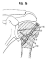
- FIG. 16 shows a fracture in the shoulder joint head similar to that in FIG by means of two cut-off set screws 80 on one side and a set screw 80 on the other side of the fracture line 14 has been fixed.
- a fracture in the shoulder joint head is shown, which means a bone screw 20 according to the invention inserted from below, a aiming arm 50 and a grub screw 80 on either side of the fracture line 14 has been fixed.
- FIG. 18 which shows a fracture in the shoulder joint head similar to FIG. 17, illustrates how the bone screw 20 is inserted from below and over two cut-off set screws 80 on one side and one Set screw 80 on the other side of the fracture line 14 completely fixed has been.
- Fig. 19 illustrates a fracture in the elbow tip, which is by means of a modified bone screw 20 according to the invention already fixed has been, with all cross bores 34 at an angle of about Extend 90 ° to the screw axis.
- a trimmed grub screw 80 is drilled in on both sides of the fracture line 14.
- FIG. 20 shows a fracture of a forearm bone near the wrist, by means of a modified bone screw according to the invention 20 without radially protruding screw head 22 and by means of two cut-off set screws 80 crossing the fracture and a set screw 80 on one side of the fracture line 14 is already fixed has been.
Abstract
Description
Die Erfindung betrifft ein Knochenfixierungssystem, das bei der operativen Versorgung von Frakturen einsetzbar ist.The invention relates to a bone fixation system used in the operative Treatment of fractures can be used.
Je nach Art und Schwere einer Fraktur kann es erforderlich sein, diese operativ zu behandeln. Gängige Verfahren hierzu sind unter anderem geschlossene Reposition, d.h. Ausrichtung der Knochenfragmente in ihre korrekte Lage, mit nachfolgender Einbohrung eines oder mehrerer Stifte aus rostfreiem Stahl über die Fraktur unter Röntgenkontrolle. Gegebenenfalls kann noch ein Gipsverband angelegt werden. Es können auch Gewindestifte verwendet werden, die mittels eines Rahmens außerhalb der Haut verbunden werden, wobei der Rahmen eine Ausrichtung der Fraktur erlaubt.Depending on the type and severity of a fracture, it may be necessary to be treated surgically. Common procedures for this include closed reduction, i.e. Alignment of the bone fragments in their correct position, with subsequent drilling of one or more pins made of stainless steel over the fracture under X-ray control. Possibly a plaster cast can still be applied. You can also use grub screws used by means of a frame outside the Skin are joined, with the frame aligning the fracture allowed.
Manche Frakturen werden unter Freilegung der Fraktur operiert, wobei die Fixierung über eine Metallplatte erfolgt, die mittels Schrauben befestigt wird.Some fractures are operated on, exposing the fracture the fixation takes place via a metal plate, which is fastened with screws becomes.
Aus der EP-A-88 311 746.7 ist eine Vorrichtung bekannt, die zur operativen Behandlung von Oberschenkelhalsbrüchen dient. Die Vorrichtung umfasst einen Schraubenabschnitt und einen mit diesem verbundenen Nagelabschnitt, der Querbohrungen aufweist. Der Nagelabschnitt wird in den Oberschenkelknochen eingeschlagen und der Schraubenabschnitt wird in den Kopf des Oberschenkelknochens eingeschraubt. Anschließend wird der Nagel über Fixierstifte, die durch seine Querbohrungen eingeführt werden, fixiert. Zur Hilfe bei der Fixierung weist die Vorrichtung eine Bohrschablone auf, über die der Operateur die Fixierstifte in die von außen nicht sichtbaren Querbohrungen einführen kann. Diese Vorrichtung ist speziell zur Behandlung von Oberschenkelhalsbrüchen entworfen und für andere Frakturarten wenig geeignet.From EP-A-88 311 746.7 a device is known which is used for the operative Treatment of fractures of the femur. The device comprises a screw portion and one connected thereto Nail section that has cross holes. The nail section is in hammered in the femur and the screw section is screwed into the head of the thigh bone. Subsequently the nail is inserted through locating pins through its cross holes are fixed. To help with the fixation, the device has a Drilling template over which the surgeon can insert the locating pins into the can insert cross holes not visible from the outside. This device is specially designed for the treatment of fractures of the femur and not very suitable for other types of fractures.
Es ist die Aufgabe der Erfindung, dem Chirurgen ein Instrument an die Hand zu geben, mit dem eine große Vielfalt von unterschiedlichen Frakturen behandelt werden kann, wobei einerseits eine einfache und sichere Handhabung durch den Chirurgen gewährleistet wird, und andererseits die Fraktur des Patienten zuverlässig in ihre richtige Lage gebracht und gehalten werden kann, so dass ihre Ausheilung unter optimalen Bedingungen erfolgen kann.It is the object of the invention to provide the surgeon with an instrument To give hand with a wide variety of different fractures can be treated, on the one hand a simple and safe Handling is guaranteed by the surgeon, and on the other hand reliably brought the patient's fracture into position and can be kept, so that their healing under optimal conditions can be done.
Die Aufgabe wird durch das erfindungsgemäße Knochenfixierungssystem gelöst und insbesondere durch
- eine Knochenschraube mit einem Schraubenkopf und einem daran anschließenden Schaftabschnitt, der einen Außengewindeabschnitt aufweist, über den die Knochenschraube in den Knochen frakturüberschreitend einschraubbar ist, wobei am Schraubenkopf eine Kopplungseinrichtung vorgesehen ist und im Schaftabschnitt mindestens eine durch den Schaftabschnitt verlaufende Fixierbohrung ausgebildet ist,
- eine extrakorporale Zielhilfe mit einem Kopplungsabschnitt und einem Zielabschnitt, wobei die Knochenschraube und die Zielhilfe über die Kopplungseinrichtung des Schraubenkopfes und den Kopplungsabschnitt des Zielabschnittes in genau einer vorgegebenen Relativlage miteinander koppelbar sind, und wobei im Zielabschnitt mindestens eine der Fixierbohrung der Knochenschraube zugeordnete und im gekoppelten Zustand mit dieser ausgerichtete Zielbohrung ausgebildet ist, und
- mindestens ein stiftförmiges Fixierelement, das zur Fixierung der Knochenschraube im Knochen bei mit der Knochenschraube gekoppelter Zielhilfe unter Verwendung der Zielbohrung durch die Fixierbohrung durchführbar ist.
- a bone screw with a screw head and an adjoining shaft section which has an external thread section via which the bone screw can be screwed into the bone in a fracture-exceeding manner, a coupling device being provided on the screw head and at least one fixing bore running through the shaft section being formed in the shaft section,
- an extracorporeal aiming aid with a coupling section and a targeting section, the bone screw and the aiming aid being able to be coupled to one another in exactly a predetermined relative position via the coupling device of the screw head and the coupling section of the targeting section, and wherein in the targeting section at least one associated with the fixing bore of the bone screw and in the coupled state is formed with this aligned target hole, and
- at least one pin-shaped fixing element which can be carried out through the fixing hole for fixing the bone screw in the bone when the aiming aid is coupled to the bone screw using the target hole.
Über die Knochenschraube erlaubt das erfindungsgemäße Knochenfixierungssystem, dass zueinander gehörende Knochenfragemente unter Aufbau einer Druckspannung fest in ihrer richtigen Relativlage aneinander gefügt werden können, d.h. eine Schrägstellung und parallele Seitenverschiebung der Fraktur in zwei Ebenen kann vermieden werden. Für das Beibehalten der richtigen Relativlage ist es zweckmäßig, die Knochenschraube drehfest zu machen oder "zu verriegeln". Diese Verriegelungsfunktion übernimmt eine in die Fixierbohrung eingebrachte Schraube oder ein gleichartig anzuwendender Nagel. Ein solches Fixierelement besitzt ein großes winkelstabilisierendes Vermögen, da das Zentrum der Winkelkräfte, die zwischen Fixierelement und Knochenschraube wirken, innerhalb der Knochenschraube wirken und nicht im Knochen selbst.Via the bone screw, the bone fixation system according to the invention allows that related bone fragments under construction a compressive stress in their correct relative position to each other can be added, i.e. an inclination and parallel side shift the fracture in two planes can be avoided. For the It is advisable to maintain the correct relative position, the bone screw to make it non-rotatable or "to lock". This locking function takes over a screw inserted in the fixing hole or a nail to be used in the same way. Such a fixing element has a large angle-stabilizing ability, since the center of the Angular forces acting between the fixing element and the bone screw, act within the bone screw and not in the bone itself.
Das Einführen von beispielsweise einem Nagel als stiftförmiges Fixierelement in die Fixierbohrung der Knochenschraube erfolgt erfindungsgemäß unter Verwendung der Zielhilfe. Da die Zielbohrung im Zielabschnitt exakt mit der Fixierbohrung fluchtet, kann der Nagel über die Zielbohrung von außen her derart eingeführt werden, dass er die Fixierbohrung genau trifft. Der Nagel wird dabei von außen in die Zielbohrung eingeführt, tritt dann aus der Zielbohrung aus, durchdringt anschließend die Haut, die gegebenenfalls durch Ansetzen eines geeigneten Schnittes vorbereitet wird, und durchdringt weitere Gewebeschichten bis zum beschädigten Knochen, dringt in den Knochen ein, bis er in die Fixierbohrung einfädelt, tritt aus dieser aus und gelangt dann wieder in den Knochen. Der gesamte Vorgang wird zweckmäßigerweise über Röntgendurchleuchtung überwacht, um insbesondere die Tiefe des Einführens des Nagels zu kontrollieren.The insertion of a nail, for example, as a pin-shaped fixing element in the fixing hole of the bone screw according to the invention using the target help. Because the target hole in the target section is exact aligned with the fixation hole, the nail can pass through the target hole be inserted from the outside in such a way that it precisely locates the fixing hole meets. The nail is inserted from the outside into the target hole, enters then out of the target hole, then penetrates the skin that if necessary prepared by making a suitable cut and penetrates further layers of tissue to the point of damage Bone, penetrates the bone until it threads into the fixation hole, emerges from it and then gets back into the bone. The whole The process is expediently monitored by X-ray fluoroscopy, especially to control the depth of insertion of the nail.
Die Zielhilfe ist abnehmbar. Sie wird nach Eindrehen der Knochenschraube an deren Kopf befestigt und nach durchgeführter Operation entfernt. Das Fixierelement kann dann kurz über dem Knochen gekürzt werden. Da kein äußerer Rahmen vorgesehen ist und auch kein Gipsverband notwendig ist, können die betreffenen Gliedmaße durch frühzeitiges Training beweglich gehalten werden und ein starker Abbau der Muskulatur kann vermieden werden.The aiming aid is removable. It becomes after screwing in the bone screw attached to their head and removed after the operation. The fixation element can then be shortened just above the bone. There no external frame is provided and no plaster cast is necessary is the affected limb through early training can be kept mobile and a strong breakdown of the muscles be avoided.
Da die Fixierelemente nahe des Knochens abgeschnitten und die Wunden gleich nach der Operation steril verbunden werden, erfolgt eine vollständig interne Fixierung, die insbesondere das Infektionsrisiko vermindert, das bei Vorrichtungen gegenwärtig ist, die eine Verspannung von Stiften außerhalb des Körpers benutzen und bei denen die Stifte in der gesamten Heilungsphase aus der Haut hervorragen, so dass an der Übergangsstelle zwischen Stift und Haut Keime in die Wunde eindringen können.Because the fixation elements are cut off near the bone and the wounds immediately after the operation sterile, a complete internal fixation, which in particular reduces the risk of infection, the is present in devices that have pin tension outside of the body and where the pins are all over Protruding healing phase from the skin, so that at the transition point germs can penetrate into the wound between the stick and the skin.
Die Verwendung einer Knochenschraube statt eines Nagels ist insbesondere deshalb von Vorteil, da durch das Vorbohren und Einschrauben der Knochenschraube weit weniger Spannungen in dem Knochen aufgebaut werden als beim Einbringen von Nägeln. Dies ist z.B. bei osteoporotischen Knochen günstiger, die dem erhöhten Risiko ausgesetzt sind, dass sie beim Hineintreiben eines Nagels brechen.The use of a bone screw instead of a nail is special therefore advantageous, because by pre-drilling and screwing in the Bone screw builds up far less tension in the bone than when inserting nails. This is e.g. in osteoporotic Bones cheaper that are at increased risk of them break when driving in a nail.
Bei einem bevorzugten Ausführungsbeispiel ist die Fixierbohrung als Schrägbohrung ausgebildet, die unter einem spitzen Winkel zur Schraubenachse verläuft, und es ist mindestens eine weitere Fixierbohrung vorgesehen ist, die als Querbohrung ausgebildet ist und rechtwinklig zur Schraubenachse verläuft, wobei der Schrägbohrung und der Querbohrung entsprechend ausgerichtete Zielbohrungen zugeordnet sind. Besonders vorteilhaft ist es, wenn mindestens zwei Fixierbohrungen als Schrägbohrungen ausgebildet sind, die unter einem spitzen Winkel zur Schraubenachse verlaufen und gegeneinander um die Schraubenachse verdreht sind. Diese räumliche Anordnung der Schraube mit den eingebrachten Fixierelementen ergibt eine besonders stabile Verspannung oder Lagefixierung der Schraube im Raum.In a preferred embodiment, the fixing hole is as Inclined hole formed at an acute angle to the screw axis runs, and there is at least one further fixing hole is provided, which is designed as a transverse bore and perpendicular to Screw axis runs, the oblique hole and the transverse hole appropriately aligned target holes are assigned. Especially It is advantageous if at least two fixing bores as inclined bores are formed at an acute angle to the screw axis run and rotated against each other around the screw axis are. This spatial arrangement of the screw with the inserted Fixing elements result in a particularly stable bracing or position fixation the screw in the room.
Bei einem besonders bevorzugten Ausführungsbeispiel sind die beiden Schrägbohrungen zwischen dem Schraubenkopf und wenigstens einer, bevorzugt mehreren und insbesondere parallel verlaufenden Querbohrungen vorgesehen, wobei diesen Bohrungen entsprechend ausgerichtete Zielbohrungen zugeordnet sind. Besonders vorteilhaft ist es, wenn die beiden Schrägbohrungen nahe dem Schraubenkopf vorgesehen sind und die Querbohrungen im Endbereich des Schaftabschnitts vorgesehen sind. Diese geometrische Konstruktion mit Fixierpunkten in drei Dimensionen trägt zu verbesserter Stabilität der Fixierung der Fraktur bei. Außerdem kann der freie Schenkel der Zielhilfe schlank gehalten werden, so dass er beim operativen Eingriff nicht stört und sein Gewicht möglichst gering bleibt.In a particularly preferred embodiment, the two are Oblique bores between the screw head and at least one, preferably several and in particular parallel transverse bores provided, these holes aligned accordingly Target holes are assigned. It is particularly advantageous if the two oblique holes near the screw head are provided and the transverse bores are provided in the end region of the shaft section. This geometric construction with fixation points in three dimensions contributes to improved stability of the fixation of the fracture. Moreover the free leg of the aiming aid can be kept slim so that it does not interfere with the operation and its weight is as low as possible remains.
Bei einem weiteren Ausführungsbeispiel umfasst die Kopplungseinrichtung des Schraubenkopfes eine in axialer Richtung der Knochenschraube verlaufende Gewindebohrung und eine Positioniereinrichtung in Form einer an der Stirnseite des Schraubenkopfes vorgesehenen Positionierausnehmung, und der Kopplungsabschnitt der Zielhilfe umfasst eine Durchgangsbohrung und eine Positioniereinrichtung in Form einer zur Positionierausnehmung komplementären Positioniererhebung. Besonders bevorzugt ist es, wenn die Positionierausnehmung eine sich radial verjüngende Nut oder zumindest eine durch die Schraubenachse verlaufende kerbenoder schlitzartige Vertiefung umfasst, wobei vorzugsweise zusätzlich zu der kerben- oder schlitzartigen Vertiefung eine randseitig am Schraubenkopf angeordnete Aussparung ausgebildet ist. Die Zielhilfe ist auf diese Weise einfach über ein standardisiertes Befestigungselement am Schraubenkopf zu befestigen, wobei die Positioniereinrichtungen die Fixierung der Zielhilfe relativ zur Knochenschraube eindeutig festlegen. Dabei ist insgesamt nur eine geringe Anzahl von Einzelteilen für das Knochenfixierungssystem erforderlich, nämlich die Knochenschraube, die Zielhilfe, das Befestigungselement und die vorgesehene Anzahl von Fixierelementen.In a further exemplary embodiment, the coupling device comprises of the screw head in the axial direction of the bone screw running threaded hole and a positioning device in shape a positioning recess provided on the end face of the screw head, and the coupling portion of the aiming aid includes a through hole and a positioning device in the form of a positioning recess complementary positioning survey. Particularly preferred it is when the positioning recess is a radially tapering one Groove or at least one notch or extending through the screw axis comprises slot-like depression, preferably in addition to the notch or slot-like recess on the edge of the screw head arranged recess is formed. The aim aid is on this Simply using a standardized fastener on the screw head to attach, the positioning means the fixation clearly define the aiming aid relative to the bone screw. It is overall only a small number of individual parts for the bone fixation system required, namely the bone screw, the aiming aid, the Fastening element and the intended number of fixing elements.
Die Zielhilfe des erfindungsgemäßen Knochenfixierungssystem ist bei einem weiteren Ausführungsbeispiel als Zielbügel mit einstückig ausgebildetem Kopplungsabschnitt und Zielabschnitt gestaltet. Vorzugsweise liegen der Zielabschnitt und die Knochenschraube im gekoppelten Zustand in einer Ebene und bilden jeweils auseinanderlaufende Schenkel eines U oder V, wobei die Schenkel bevorzugt zumindest näherungsweise gleich lang sind. Diese Ausgestaltung bietet einen kompakten räumlichen Aufbau, der unter einer Vielzahl von anatomischen Bedingungen einsetzbar ist, wie etwa bei Frakturen eines Unterarmknochens in der Nähe des Handgelenks oder Frakturen des äußeren Fußknöchels.The aim of the bone fixation system according to the invention is at a further embodiment as a aiming arm with a one-piece design Coupling section and target section designed. Preferably are the target section and the bone screw in the coupled state in one plane and each form diverging legs a U or V, the legs preferably at least approximately are the same length. This configuration offers a compact spatial Structure that can be used under a variety of anatomical conditions such as fractures of a forearm bone near the Wrist or fractures of the outer ankle.
Eine im eingeschraubten Zustand dem Knochen zugewandte Unterseite des Schraubenkopfes ist bei einer weiteren Ausführungsform als an die Form des jeweiligen Knochens angepasste Anlagefläche ausgebildet.An underside facing the bone when screwed in the screw head is in a further embodiment than to Form of the respective bone adapted contact surface.
Bei einer anderen Ausführungsform ist in dem Zielabschnitt zumindest eine Aufnahmebohrung vorgesehen, in die eine Zielhülse mit einer darin ausgebildeten Zielbohrung einbringbar, vorzugsweise steckbar, ist, die mit der Fixierbohrung ausgerichtet ist und in Richtung der Fixierbohrung verschiebbar ist. Die Zielhülse verlängert die Zielbohrung in Richtung der Fixierbohrung, wodurch eine noch genauere Führung des Fixierelements zur Fixierbohrung gewährleistet ist.In another embodiment, at least in the target section a receiving bore is provided, in which a target sleeve with one therein trained target hole can be introduced, preferably plugged, with the fixing hole is aligned and in the direction of the fixing hole is movable. The target sleeve extends the target bore towards the Fixing hole, which ensures an even more precise guidance of the fixing element for the fixing hole is guaranteed.
Ein weiteres Ausführungsbeispiel des erfindungsgemäßen Knochenfixierungssystems zeichnet sich dadurch aus, dass die Zielhilfe zumindest im Bereich des Kopplungsabschnitts aus für Röntgenstrahlen durchlässigem Material, beispielsweise kohlefaserverstärktem Kunststoff, besteht. Eine Durchlässigkeit für Röntgenstrahlung ist zur Röntgenkontrolle während des operativen Eingriffs angebracht, um jederzeit eine gute Sicht auf die zu fixierenden Knochen und die Schraube und die Fixierelemente, die für die Fixierung der Knochen verwendet werden, zu haben.Another embodiment of the bone fixation system according to the invention is characterized in that the target help at least in Area of the coupling section made of X-ray transparent Material, for example carbon fiber reinforced plastic, is made. A X-ray transmission is for X-ray control during of the surgical procedure to ensure a good view of the patient at all times bones to be fixed and the screw and fixation elements needed for to have the fixation of the bones used.
Eine weitere vorteilhafte Ausführungsform des Knochenfixierungssystems ist durch eine universelle Zielhilfe gekennzeichnet, die mit Knochenschrauben mit unterschiedlichen Längen und/oder unterschiedlichen Anzahlen und Lagen von Fixierbohrungen verwendbar ist. Eine solche Zielhilfe, die für mehrere bzw. unterschiedliche Knochenschrauben geeignet ist, trägt zur Kostensenkung bei und hält das Instrumentarium für die Operation übersichtlicher.Another advantageous embodiment of the bone fixation system is characterized by a universal aiming aid, with bone screws with different lengths and / or different Numbers and positions of fixing holes can be used. Such Aiming aid that is suitable for several or different bone screws is contributing to cost reduction and keeping the tools for Operation clearer.
Die Erfindung betrifft außerdem eine Knochenschraube sowie eine Zielhilfe für ein erfindungsgemäßes Knochenfixierungssystem.The invention also relates to a bone screw and a targeting aid for a bone fixation system according to the invention.
Weitere Ausführungsbeispiele der Erfindung sind in den Unteransprüchen, der Beschreibung sowie der Zeichnung angegeben.Further embodiments of the invention are in the subclaims, the description and the drawing.
Die Erfindung wird im Folgenden beispielhaft anhand der Zeichnung beschrieben. In dieser zeigen:
- Fig. 1
- eine Perspektivansicht einer Ausführungsform des erfindungsgemäßen Knochenfixierungssystems,
- Fig. 2
- eine Schnittansicht durch das Knochenfixierungssystems von Fig. 1,
- Fig. 3
- eine Seitenansicht des Knochenfixierungssystems von Fig. 1,
- Fig. 4
- eine Schnittansicht durch eine erfindungsgemäße Knochenschraube,
- Fig. 5
- eine Perspektivansicht auf den Kopf einer Knochenschraube,
- Fig. 6
- eine Teilschnittansicht durch eine erfindungsgemäße Knochenschraube,
- Fig. 7
- ein weiteres Ausführungsbeispiel einer erfindungsgemäßen Knochenschraube die einen Schraubenkopf mit einer konkav ausgebildeten Unterseite aufweist,
- Fig. 8
- ein weiteres Ausführungsbeispiel einer erfindungsgemäßen Knochenschraube ohne radial überstehenden Schraubenkopf,
- Fig. 9
- ein Anwendungsbeispiel des erfindungsgemäßen Knochenfixierungssystems bei einer Fraktur eines Unterarmknochens in der Nähe des Handgelenks,
- Fig. 10
- ein Anwendungsbeispiel ähnlich wie bei Fig. 9 mit abgenommener Zielhilfe und gekürzten Fixierelementen,
- Fig. 11
- ein Anwendungsbeispiel des erfindungsgemäßen Knochenfixierungssystems bei einer Fraktur der Ellenbogenspitze,
- Fig. 12
- ein Anwendungsbeispiel ähnlich wie bei Fig. 11 mit abgenommener Zielhilfe und gekürzten Fixierelementen,
- Fig. 13
- ein Anwendungsbeispiel des erfindungsgemäßen Knochenfixierungssystems bei einer Fraktur des äußeren Fußknöchels,
- Fig. 14
- ein Anwendungsbeispiel ähnlich wie bei Fig. 13 mit abgenommener Zielhilfe und gekürzten Fixierelementen,
- Fig. 15
- ein Anwendungsbeispiel des erfindungsgemäßen Knochenfixierungssystems bei einer Fraktur im Schultergelenkkopf,
- Fig. 16
- ein Anwendungsbeispiel ähnlich wie bei Fig. 15 mit abgenommener Zielhilfe und gekürzten Fixierelementen,
- Fig. 17
- ein weiteres Anwendungsbeispiel des erfindungsgemäßen Knochenfixierungssystems bei einer Fraktur im Schultergelenkkopf,
- Fig. 18
- ein Anwendungsbeispiel ähnlich wie bei Fig. 17 mit abgenommener Zielhilfe und gekürzten Fixierelementen,
- Fig. 19
- ein Anwendungsbeispiel des erfindungsgemäßen Knochenfixierungssystems bei einer Fraktur in der Ellenbogenspitze mittels modifizierter Knochenschraube, und
- Fig. 20
- ein weiteres Anwendungsbeispiel des erfindungsgemäßen Knochenfixierungssystems bei einer Fraktur eines Unterarmknochens in der Nähe des Handgelenks.
- Fig. 1
- 2 shows a perspective view of an embodiment of the bone fixation system according to the invention,
- Fig. 2
- 2 shows a sectional view through the bone fixation system from FIG. 1,
- Fig. 3
- 2 shows a side view of the bone fixation system from FIG. 1,
- Fig. 4
- 2 shows a sectional view through a bone screw according to the invention,
- Fig. 5
- a perspective view of the head of a bone screw,
- Fig. 6
- 2 shows a partial sectional view through a bone screw according to the invention,
- Fig. 7
- another embodiment of a bone screw according to the invention which has a screw head with a concave underside,
- Fig. 8
- another embodiment of a bone screw according to the invention without a radially projecting screw head,
- Fig. 9
- 1 shows an application example of the bone fixation system according to the invention for a fracture of a forearm bone near the wrist,
- Fig. 10
- an application example similar to Fig. 9 with removed aiming aid and shortened fixing elements,
- Fig. 11
- an application example of the bone fixation system according to the invention for a fracture of the elbow tip,
- Fig. 12
- an application example similar to FIG. 11 with removed aiming aid and shortened fixing elements,
- Fig. 13
- 1 shows an application example of the bone fixation system according to the invention for a fracture of the outer ankle,
- Fig. 14
- an application example similar to Fig. 13 with removed aiming aid and shortened fixing elements,
- Fig. 15
- 1 shows an application example of the bone fixation system according to the invention for a fracture in the head of the shoulder joint,
- Fig. 16
- 15 shows an application example similar to FIG. 15 with the aiming aid removed and the fixing elements shortened,
- Fig. 17
- another application example of the bone fixation system according to the invention for a fracture in the shoulder joint head,
- Fig. 18
- 17 shows an application example similar to FIG. 17 with the aiming aid removed and the fixing elements shortened,
- Fig. 19
- an application example of the bone fixation system according to the invention for a fracture in the elbow tip by means of modified bone screw, and
- Fig. 20
- a further application example of the bone fixation system according to the invention for a fracture of a forearm bone near the wrist.
Die Perspektivansicht von Fig. 1 zeigt beispielhaft ein erfindungsgemäßes
Knochenfixierungssystem 10, das insbesondere für den Einsatz bei Frakturen
von Unterarmknochen in der Nähe des Handgelenks ausgelegt ist.
Eine Zielhilfe in der Form eines Zielbügels 50 ist an einem Kopplungsabschnitt
54 über eine Schraube 70 (Fig. 2) an einer Kopplungseinrichtung
40 (Fig. 2 und z.B. Fig. 5) eines Schraubenkopfes 22 einer Knochenschraube
20 befestigt. Der Zielbügel 50 bildet dabei zusammen mit der
Knochenschraube 20 die Form eines V mit in einer Ebene liegenden
Schenkeln von etwa gleicher Länge, wobei der Öffnungswinkel zwischen
den Schenkeln etwa 25° beträgt.The perspective view of Fig. 1 shows an example of an inventive
In Aufnahmebohrungen 90, 92, 94 in einem Zielabschnitt 52 des Zielbügels
50 sind Zielhülsen 68 eingesetzt bzw. in einer Position vor Aufnahmebohrungen
92 dargestellt. Durch die Zielhülsen 68 sind Fixierelemente 80
in der Form von Nägeln hindurchgeführt, die sich auch durch Fixierbohrungen
30, 32, 34 hindurch erstrecken, die im Schaftabschnitt 24 und
einem an diesem vorgesehenen Außengewindeabschnitt 26 der Knochenschraube
20 ausgebildet sind.In receiving bores 90, 92, 94 in a
Die beiden in der Nähe des Schraubenkopfes 22 vorgesehenen Fixierbohrungen
sind Schrägbohrungen 30, 32, die gegeneinander 22° um die
Schraubenachse A verdreht sind und unter einem Winkel von 45° zur
Schraubenachse A in einem Abstand von etwa 5 mm zueinander durch
die Knochenschraube 20 hindurch verlaufen, so dass die Mittellinien der
Schrägbohrungen 30, 32 windschiefe, kreuzungsfreie Geraden bilden. Im
unteren Bereich des Schaftabschnitts 24 sind als Querbohrungen 34
ausgebildete Fixierbohrungen vorgesehen, d.h. die Querbohrungen 34
stehen senkrecht auf der Achse A der Knochenschraube 20. Im Zielabschnitt
52 des Zielbügels 50 sind Aufnahmebohrungen 90, 92, 94 für
Zielhülsen 68 in einer entsprechenden Anzahl vorgesehen.The two fixing bores provided near the
Die Knochenschraube 20 spannt zusammen mit jedem in eine entsprechende
Fixierbohrung 30, 32, 34 eingeführten Nagel 80 eine Ebene auf, so
dass im gezeigten Fall drei Ebenen gebildet sind, die winklig aufeinander
stehen und eine stabile geometrische Konstruktion bilden.The
Fig. 2 zeigt das Knochenfixierungssystem 10 von Fig. 1 in einer Schnittansicht.
Der Kopplungsabschnitt 54 des Zielbügels 50 ist mit der Kopplungseinrichtung
40 am Schraubenkopf 22 der Knochenschraube 20 über
eine Schraube 70 verbindbar. Die Kopplungseinrichtung 40 besteht aus
einem Innengewinde 42, in das die Schraube 70 eindrehbar ist, und einer
Positionierausnehmung 44. Der Kopplungsabschnitt 54 des Zielbügels 50
umfasst ein Durchgangsloch 58 für die Schraube 70 mit einer Flachsenkung
98 zur Aufnahme des Kopfes der Schraube 70 und eine zur Positionierausnehmung
44 komplementäre Positioniererhebung 56. Beim Aufsetzen
des Zielbügels 50 auf die Kopplungseinrichtung 40 gelangt die Positioniererhebung
56 des Kopplungsabschnitts 54 in Eingriff mit der Positionierausnehmung
44 der Kopplungseinrichtung 40, so dass nur eine einzige
vorgegebene Relativlage zwischen Knochenschraube 20 und Zielbügel
50 hergestellt werden kann und somit eine korrekte Ausrichtung der
Zielbohrungen 60, 62, 64 mit ihren zugehörigen Fixierbohrungen 30, 32,
34 gewährleistet wird.FIG. 2 shows the
Die Aufnahmebohrungen 90, 92, 94 für die Zielhülse 68 weisen eingangsseitig
eine Flachsenkung 96 auf, um eine gute Anlage eines an der Zielhülse
68 vorgesehenen Absatzes 66 am Zielbügel 50 sicherzustellen. Die
Zielhülsen 68 sind eintrittsseitig angefast, um sie leicht in die Aufnahmebohrungen
90, 92, 94 einführen zu können.The receiving bores 90, 92, 94 for the
In Fig. 3 ist zu erkennen, dass der Zielabschnitt 52 im Bereich des Kopplungsabschnitts
54 breiter als an seinem freien Schenkel gestaltet ist, da
die beiden zu den Schrägbohrungen 30, 32 gehörenden Aufnahmebohrungen
90, 92, 94 für die Zielhülse 68 in Bezug auf die Mittellinie des
Zielbügels 50 seitlich versetzt vorgesehen sind.3 that the
Die Schnittansicht von Fig. 4 und die Perspektivansicht von Fig. 5 verdeutlichen
im Besonderen die Kopplungseinrichtung 40 einer weiteren
Ausführungsform einer Knochenschraube 20. Die Kopplungseinrichtung
40 umfasst die Positionierausnehmung 44, die eine stirnseitig am Schraubenkopf
22 vorgesehene, sich in radialer Richtung verjüngende Nut ist.
Zentral in der Stirnseite des Schraubenkopfes 22 ist ein Innensechskant
46 ausgebildet, der als Aufnahme für einen Sechskantschlüssel (nicht
gezeigt) als Eindrehwerkzeug dient. Am Ende des Außengewindeabschnitts
26 der Knochenschraube 20 sind gemäß Fig. 4 zwei oder mehr Schneidkanten
38 vorgesehen, da es sich bei der Knochenschraube 20 um eine
Schraube mit selbstschneidendem Gewinde handelt, das ggf. lediglich ein
Vorbohren, aber keinen separaten Arbeitsgang zum Gewindeschneiden
erfordert. Unter bestimmten Umständen, wie etwa bei einem verhältnismäßig
kleinen Durchmesser der Knochenschraube 20 in Bezug auf den
Knochen, kann auch auf das Vorbohren verzichtet werden. Ferner ist in
Achsrichtung durch die gesamte Knochenschraube 20 hindurch eine
Durchgangsbohrung 28 vorgesehen, die der Führung dient, wenn vorher
ein Kirschner-Draht zur Festlegung der Achslage eingebracht wurde.
Ferner sind in Fig. 5 die windschiefen Achsen der Bohrungen 30, 32
veranschaulicht. The sectional view of FIG. 4 and the perspective view of FIG. 5 clarify
in particular the
Fig. 6 veranschaulicht ein weiteres Ausführungsbeispiel der erfindungsgemäßen
Knochenschraube 20 mit einer andersartig gestalteten Kopplungseinrichtung
40. An der Stirnseite des Schraubenkopfes 22 sind zwei
sich in radialer Richtung mittig über den Schraubenkopf 22 hinweg
erstreckende Kerben rechtwinklig zueinander vorgesehen, in welchen der
Zielbügel mit vorstehenden Dachführungen positioniert wird und an die
auch ein Schraubendreher angesetzt werden kann, um bei nicht aufgesetzter
Zielhilfe 50 die Knochenschraube 20 in den Knochen einzudrehen.
Die Befestigung des Zielbügels 50 in einer einzigen bezüglich Drehung
vorgegebenen Relativlage wird dadurch gewährleistet, dass randseitig am
Schraubenkopf 22 eine Positionierausnehmung 44 in der Form einer
Aussparung 48 ausgebildet ist, mit der eine komplementäre Positioniererhebung
56 des Zielbügels 50 (nicht gezeigt) eine Grobausrichtung im
richtigen Quadranten gewährleistet.6 illustrates a further embodiment of the
Die schematische Ansicht von Fig. 7 veranschaulicht einen Schraubenkopf
eines anderen Ausführungsbeispiels, dessen Unterseite 18 zur Anlage
an ein entsprechend geformtes Knochenstück konkav ausgebildet ist.The schematic view of Fig. 7 illustrates a screw head
of another embodiment, the
In Fig. 8 ist ein weiterer Schraubenkopf eines anderen Ausführungsbeispiels einer Knochenschraube dargestellt, der keinen radialen Überstand aufweist und somit z.B. für beengtere Platzverhältnisse geeignet ist.8 is another screw head of another embodiment shown a bone screw that has no radial projection and thus e.g. is suitable for confined spaces.
Weitere Ausführungsformen können noch andere Modifikationen der
Knochenschraube 20 aufweisen. Bei sehr kleinen Frakturfragmenten
kann es zweckmäßig sein, ausschließlich Querbohrungen 34, die unter
90° zur Schraubenachse stehen, anstelle von Schrägbohrungen zu verwenden. Other embodiments may include other modifications of the
Die Führungshülsen 68 der Zielhilfe 50 können weggelassen werden,
wenn beispielsweise eine Schraube zur Fixierung der Knochenschraube
20 verwendet wird, deren Kopf- und Gewindeteil mit der Bohrung im
Zielbügel und in der eigentlichen Knochenschraube übereinstimmen.The
Im Folgenden sind Abmessungen eines erfindungsgemäßen Knochenfixierungssystems
10, das beispielhaft zur Behandlung eines Bruches eines
Unterarmknochens in der Nähe des Handgelenks eingesetzt wird, angegeben.
Die Länge des Schaftabschnitts 24 beträgt zwischen 4 cm und 10 cm
und kann in Abhängigkeit von den jeweiligen anatomischen Verhältnissen
entsprechend gewählt werden. In dem dargestellten Fall beträgt sie etwa 4
cm. Der Außendurchmesser des Außengewindeabschnitts 26 der Knochenschraube
20 beträgt etwa 6 mm. Das Gewinde des Außengewindeabschnitts
26 der Knochenschraube 20 kann ein eingängiges Gewinde sein,
ist aber bevorzugt ein zweigängiges Gewinde mit einer Steigung von etwa 2
mm pro Gang. Die Fixierbohrungen 30, 32, 34 haben einen Durchmesser
von 1,6 mm.The following are dimensions of a bone fixation system according to the
Die Knochenschraube 20 und die Fixierelemente bestehen vorzugsweise
aus Titan, um eine galvanische Reaktion zwischen verschiedenen Metallen
zu vermeiden. Für die Knochenschraube 20 kann aber auch ein vom
Körper wieder aufnehmbares Material, beispielsweise Polyglykolid oder
Poly-L-Laktid, in Betracht gezogen werden. Die Zielhilfe 50 besteht aus
kohlefaserverstärktem Kunststoff und ist daher für Röntgenstrahlen
durchlässig.The
Anhand von Fig. 9 wird nun beispielhaft der Einsatz des erfindungsgemäßen
Systems 10 bei der operativen Behandlung eines Bruches eines Unterarmknochens
in der Nähe des Handgelenks beschrieben. The use of the invention is now exemplified with reference to FIG. 9
Die Fraktur wird zuerst unter Röntgendurchleuchtung geschlossen zurechtgelegt
(ohne Operation), worauf ein kleiner Hautschnitt (ca. 1 cm) an
der Spitze des Radiusknochens, gegen die Mittelhand herunter, auf der
Seite des Daumens vorgenommen wird. Nach Vorbohrung unter einem
vom Chirurgen zu wählenden Winkel zur Längsachse des Radiusknochens
wird die Knochenschraube 20 über die Fraktur 14 eingeschraubt (ausgehend
von der Radiusknochenspitze unterhalb der Fraktur am Handgelenk
- die Fraktur durchkreuzend - und durch den Radiusknochen oberhalb
der Fraktur näher am Ellbogen). Hierdurch wird eine Fixierung der Fraktur
erhalten. Wenn die Frakturflächen gut erhalten sind (keine Quetschfraktur),
kann im Bedarfsfalle eine Überbohrung mit etwas größerem
Durchmesser des Schraubenlochs in dem nahe am Handgelenk gelegenen
Frakturfragment ausgeführt werden, wodurch bewirkt wird, dass das
Gewinde der Knochenschraube 20 in diesem Teil nicht eingreift, sondern
nur auf der anderen Seite der Frakturlinie 14. Die eingeschraubte Knochenschraube
20 erzeugt dann eine Kompressionswirkung in der Frakturlinie
14, was die Stabilität der Fixierung verstärkt.The fracture is first closed under X-ray fluoroscopy
(without surgery), followed by a small skin incision (approx. 1 cm)
the tip of the radius bone, down against the metacarpus, on the
Side of the thumb is made. After pre-drilling under one
Angle to be selected by the surgeon in relation to the longitudinal axis of the radius bone
the
Nachdem die Schraube 20 angebracht worden ist, wird der Zielbügel 50
am Schraubenkopf 22 festgeschraubt. In die Aufnahmebohrungen 90, 92,
94 des Zielbügels 50 werden die Zielhülsen 68 eingebracht. Über Stechlöcher
in der Haut können die Zielhülsen 68 durch die Zielbohrungen 60,
62, 64 im Zielbügel 50, durch die Haut hindurch und gegen den Knochen
eingeführt werden. Über die Zielhülsen 68 können durchgehende Gewindestifte
durch den nahe dem Zielbügel 50 gelegenen Knochen, durch die
Fixierbohrungen 30, 32, 34 in der Knochenschraube 20 und durch den
von dem Zielbügel 50 entfernten Knochen eingebohrt werden. Sobald die
erforderliche Anzahl Gewindestifte 80 durch den Knochen und die Knochenschraube
20 eingeführt worden ist - in diesem Fall zwei Gewindestifte
80, jeweils einer auf jeder Seite der Fraktur - werden die Gewindestifte 80
neben dem Knochen abgeschnitten, der Zielbügel 50 wird entfernt und die
kleinen Wunden werden zusammengenäht oder verbunden.After the
Fig. 10 zeigt einen Bruch eines Unterarmknochens in der Nähe des Handgelenks,
der ähnlich wie bei Fig. 9. repositioniert (richtig gestellt) und
mittels einer erfindungsgemäßen Knochenschraube 20 fixiert worden ist.
Die Knochenschraube 20 ist mittels zweier Gewindestifte 80 auf der einen
Seite und eines Gewindestifts 80 auf der anderen Seite der Frakturlinie 14
fertig fixiert worden. Die Stifte 80 sind gleich außerhalb des Knochens
abgeschnitten.10 shows a fracture of a forearm bone near the wrist,
which is repositioned (correctly positioned) as in FIG. 9 and
has been fixed by means of a
In Fig. 11 ist eine Fraktur im Olecranon (prox. Ulna) dargestellt, die repositioniert
und mittels einer Knochenschraube 20 fixiert worden ist. Am
Zielbügel 50 sind die Zielhülsen 68 angebracht und ein Gewindestift 80 ist
beiderseits der Frakturlinie 14 eingebohrt.FIG. 11 shows a fracture in the olecranon (proximal ulna) that is repositioning
and has been fixed by means of a
Fig. 12 veranschaulicht eine Fraktur in der Ellenbogenspitze ähnlich wie
in Fig. 11, die mittels einer Knochenschraube 20 und zweier jeweils beiderseits
der Frakturlinie 14 eingebrachter, abgeschnittener Gewindestifte
80 fertig fixiert worden ist.Figure 12 illustrates a fracture in the elbow tip similar to
in Fig. 11, by means of a
Eine Fraktur im äußeren Malleolus lateralis (distale Fibula), die repositioniert
und mittels einer erfindungsgemäßen Knochenschraube 20, eines
Zielbügels 50 und eines Gewindestifts 80 beiderseits der Frakturlinie 14
fertig fixiert worden ist, ist in Fig. 13 gezeigt.A fracture in the outer lateral malleolus (distal fibula) that repositions
and by means of a
In Fig. 14 ist eine Fraktur im Malleolus lateralis ähnlich wie in Fig. 13
gezeigt, die mittels zweier abgeschnittener Gewindestifte 80 auf der einen
Seite und eines Gewindestifts 80 auf der anderen Seite der Frakturlinie 14
fertig fixiert worden ist. A fracture in the lateral malleolus in FIG. 14 is similar to that in FIG. 13
shown, by means of two cut-
Die Darstellung in Fig. 15 veranschaulicht eine Fraktur im Schultergelenkkopf
mit minimaler Fehlausrichtung, welche mittels einer von oben
eingeführten erfindungsgemäßen Knochenschraube 20, eines Zielbügels
50 und eines Gewindestifts 80 beiderseits der Frakturlinie 14 fertig fixiert
worden ist.The illustration in FIG. 15 illustrates a fracture in the head of the shoulder joint
with minimal misalignment, which by means of a from above
introduced
Fig. 16 zeigt eine Fraktur im Schultergelenkkopf ähnlich wie in Fig. 15, die
mittels zweier abgeschnittener Gewindestifte 80 auf der einen Seite und
eines Gewindestifts 80 auf der anderen Seite der Frakturlinie 14 fertig
fixiert worden ist.FIG. 16 shows a fracture in the shoulder joint head similar to that in FIG
by means of two cut-
In Fig. 17 ist eine Fraktur im Schultergelenkkopf verdeutlicht, die mittels
einer von unten eingeführten erfindungsgemäßen Knochenschraube 20,
eines Zielbügels 50 und eines Gewindestifts 80 beiderseits der Frakturlinie
14 fertig fixiert worden ist.In Fig. 17 a fracture in the shoulder joint head is shown, which means
a
Fig. 18, die ähnlich wie Fig. 17 eine Fraktur im Schultergelenkkopf zeigt,
veranschaulicht, wie die Knochenschraube 20 von unten eingeführt und
über zwei abgeschnittene Gewindestifte 80 auf der einen Seite und einen
Gewindestift 80 auf der anderen Seite der Frakturlinie 14 fertig fixiert
worden ist.18, which shows a fracture in the shoulder joint head similar to FIG. 17,
illustrates how the
Fig. 19 veranschaulicht eine Fraktur in der Ellbogenspitze, die mittels
einer modifizierten erfindungsgemäßen Knochenschraube 20 fertig fixiert
worden ist, wobei sich alle Querbohrungen 34 unter einem Winkel von ca.
90° zur Schraubenachse erstrecken. Ein abgeschnittener Gewindestift 80
ist beiderseits der Frakturlinie 14 eingebohrt.Fig. 19 illustrates a fracture in the elbow tip, which is by means of
a modified
Fig. 20 zeigt einen Bruch eines Unterarmknochens in der Nähe des Handgelenks,
der mittels einer modifizierten erfindungsgemäßen Knochenschraube
20 ohne radial hervorstehenden Schraubenkopf 22 und mittels
zweier abgeschnittener Gewindestifte 80 die Fraktur überschreitend und
eines Gewindestifts 80 auf einer Seite der Frakturlinie 14 fertig fixiert
worden ist. 20 shows a fracture of a forearm bone near the wrist,
by means of a modified bone screw according to the
- 1010
- KnochenfixierungssystemThe bone fixation system
- 1414
- Frakturliniefracture line
- 1818
- Unterseite SchraubenkopfBottom screw head
- 2020
- Knochenschraubebone screw
- 2222
- Schraubenkopfscrew head
- 2424
- Schaftabschnittshank portion
- 2626
- AußengewindeabschnittExternally threaded section
- 2828
- DurchgangsbohrungThrough Hole
- 3030
- Fixierbohrung, SchrägbohrungFixing hole, oblique hole
- 3232
- Fixierbohrung, SchrägbohrungFixing hole, oblique hole
- 3434
- Fixierbohrung, QuerbohrungFixing hole, cross hole
- 3838
- Schneidkante GewindeCutting edge thread
- 4040
- Kopplungseinrichtungcoupling device
- 4242
- Gewindebohrungthreaded hole
- 4444
- Positioniereinrichtung, PositionierausnehmungPositioning device, positioning recess
- 4646
- InnensechskantAllen
- 4848
- Aussparungrecess
- 5050
- Zielhilfe, ZielbügelAiming aid, aiming arm
- 5252
- Zielabschnitttarget portion
- 5454
- Kopplungsabschnittcoupling portion
- 5656
- Positioniereinrichtung, PositioniererhebungPositioning device, positioning survey
- 5858
- DurchgangslochThrough Hole
- 6060
- Zielbohrungdirectional drilling
- 6262
- Zielbohrungdirectional drilling
- 6464
- Zielbohrungdirectional drilling
- 6666
- ZielhülsenabsatzTarget sleeve paragraph
- 6868
- Zielhülsetarget sleeve
- 7070
- Schraube screw
- 8080
- Fixierelementfixing
- 9090
- Aufnahmebohrunglocation hole
- 9292
- Aufnahmebohrunglocation hole
- 9494
- Aufnahmebohrunglocation hole
- 9696
- Flachsenkungflat reduction
- 9898
- Flachsenkungflat reduction
- AA
- Schraubenachsescrew axis
Claims (16)
dadurch gekennzeichnet, dass
die Fixierbohrung (30) als Schrägbohrung ausgebildet ist, die unter einem spitzen Winkel zur Schraubenachse (A) verläuft, und dass mindestens eine weitere Fixierbohrung (34) vorgesehen ist, die als Querbohrung ausgebildet ist und rechtwinklig zur Schraubenachse (A) verläuft, wobei der Schrägbohrung (30) und der Querbohrung (34) entsprechend ausgerichtete Zielbohrungen (60, 64) zugeordnet sind.Bone fixation system according to claim 1,
characterized in that
the fixing bore (30) is designed as an oblique bore, which runs at an acute angle to the screw axis (A), and that at least one further fixing bore (34) is provided, which is designed as a transverse bore and extends at right angles to the screw axis (A), the Oblique bore (30) and the transverse bore (34) are assigned correspondingly aligned target bores (60, 64).
dadurch gekennzeichnet, dass
mindestens zwei Fixierbohrungen (30, 32) als Schrägbohrungen ausgebildet sind, die unter einem spitzen Winkel zur Schraubenachse (A) verlaufen und gegeneinander um die Schraubenachse (A) verdreht sind, wobei den Schrägbohrungen (30, 32) entsprechend ausgerichtete Zielbohrungen (60, 62) zugeordnet sind, wobei insbesondere die beiden Schrägbohrungen (30, 32) zwischen dem Schraubenkopf (22) und wenigstens einer, bevorzugt mehreren und insbesondere parallel verlaufenden Querbohrungen (34) vorgesehen sind, wobei diesen Bohrungen (30, 32, 34) entsprechend ausgebildete Zielbohrungen (60, 62, 64) zugeordnet sind und/oder die beiden Schrägbohrungen (30, 32) nahe dem Schraubenkopf (22) und die Querbohrungen (34) im Endbereich des Schaftabschnittes (24) vorgesehen sind. Bone fixation system according to claim 1 or 2,
characterized in that
at least two fixing bores (30, 32) are designed as inclined bores, which run at an acute angle to the screw axis (A) and are rotated relative to one another about the screw axis (A), the target bores (60, 62) correspondingly aligned with the inclined bores (30, 32) ) are assigned, with in particular the two oblique bores (30, 32) being provided between the screw head (22) and at least one, preferably a plurality of and in particular parallel transverse bores (34), these bores (30, 32, 34) having appropriately designed target bores (60, 62, 64) and / or the two oblique bores (30, 32) near the screw head (22) and the transverse bores (34) are provided in the end region of the shaft section (24).
dadurch gekennzeichnet, dass
die Kopplungseinrichtung (40) des Schraubenkopfes (22) eine in axialer Richtung der Knochenschraube (20) verlaufende Gewindebohrung (42) und eine Positioniereinrichtung (44) in Form einer an der Stirnseite des Schraubenkopfes (22) vorgesehenen Positionierausnehmung umfasst, und dass der Kopplungsabschnitt (54) der Zielhilfe (50) ein Durchgangsloch (58) und eine Positioniereinrichtung (56) in Form einer zur Positionierausnehmung komplementären Positioniererhebung umfasst, wobei insbesondere die Positionierausnehmung (44) eine sich radial verjüngende Nut oder zumindest eine durch die Schraubenachse (A) verlaufende kerben- oder schlitzartige Vertiefung umfasst, wobei vorzugsweise zusätzlich zu der kerben- oder schlitzartigen Vertiefung eine randseitig am Schraubenkopf (22) angeordnete Aussparung (48) ausgebildet ist und/oder bei nicht gekoppelter Zielhilfe (50) an die Positioniereinrichtung (44) der Knochenschraube (20) ein Eindrehwerkzeug ansetzbar ist, und/oder an der Stirnseite des Schraubenkopfes (22) ein Innensechskant (46) als Aufnahme für ein Eindrehwerkzeug vorgesehen ist.Bone fixation system according to one of the preceding claims,
characterized in that
the coupling device (40) of the screw head (22) comprises a threaded bore (42) running in the axial direction of the bone screw (20) and a positioning device (44) in the form of a positioning recess provided on the end face of the screw head (22), and that the coupling section ( 54) of the aiming aid (50) comprises a through hole (58) and a positioning device (56) in the form of a positioning elevation which is complementary to the positioning recess, in particular the positioning recess (44) having a radially tapering groove or at least one notch running through the screw axis (A) - or slit-like depression, wherein, in addition to the notch-like or slit-like depression, a recess (48) is provided on the edge of the screw head (22) and / or, when the aiming aid (50) is not coupled, to the positioning device (44) of the bone screw (20 ) a screwing tool can be used, and / or on the end face of the Screw head (22) an internal hexagon (46) is provided as a receptacle for a screwing tool.
dadurch gekennzeichnet, dass
die Zielhilfe (50) als Zielbügel mit einstückig ausgebildetem Kopplungsabschnitt (54) und Zielabschnitt (52) gestaltet ist. Bone fixation system according to one of the preceding claims,
characterized in that
the aiming aid (50) is designed as a aiming arm with an integrally formed coupling section (54) and aiming section (52).
dadurch gekennzeichnet, dass
der Zielabschnitt (52) der Zielhilfe (50) und die Knochenschraube (20) im gekoppelten Zustand in einer Ebene liegen und jeweils auseinanderlaufende Schenkel eines U oder V bilden, wobei die Schenkel bevorzugt zumindest näherungsweise gleich lang sind.Bone fixation system according to one of the preceding claims,
characterized in that
the target section (52) of the aiming aid (50) and the bone screw (20) in the coupled state lie in one plane and each form diverging legs of a U or V, the legs preferably being at least approximately the same length.
dadurch gekennzeichnet, dass
die Knochenschraube (20) eine in axialer Richtung verlaufende Durchgangsbohrung (28) aufweist, und/oder eine im eingeschraubten Zustand dem Knochen zugewandte Unterseite (18) des Schraubenkopfes (22) als an die Form des jeweiligen Knochens angepasste Anlagefläche ausgebildet ist. Bone fixation system according to one of the preceding claims,
characterized in that
the bone screw (20) has a through hole (28) running in the axial direction, and / or an underside (18) of the screw head (22) facing the bone in the screwed-in state is designed as a contact surface adapted to the shape of the respective bone.
dadurch gekennzeichnet, dass
die Knochenschraube (20) einen Gewindedurchmesser zwischen 4 mm und 12 mm, vorzugsweise zwischen 5 mm und 8 mm, aufweist, und/oder die Knochenschraube (20) eine Länge zwischen 3 cm und 15 cm, vorzugsweise zwischen 4 cm und 10 cm, aufweist, und/oder die Knochenschraube (20) ein mehrgängiges, vorzugsweise zweigängiges, Außengewinde aufweist, und/oder die Steigung des Gewindes der Knochenschraube (20) zwischen 1 mm und 3 mm, vorzugsweise etwa 2 mm, pro Gang beträgt, und/oder die Knochenschraube (20) ein selbstschneidendes Gewinde aufweist, und/oder die Fixierbohrungen (30, 32, 34) einen Durchmesser zwischen 1 mm und 3 mm, vorzugsweise zwischen 1,6 mm und 2 mm, aufweisen.Bone fixation system according to one of the preceding claims,
characterized in that
the bone screw (20) has a thread diameter between 4 mm and 12 mm, preferably between 5 mm and 8 mm, and / or the bone screw (20) has a length between 3 cm and 15 cm, preferably between 4 cm and 10 cm , and / or the bone screw (20) has a multi-start, preferably two-start, external thread, and / or the pitch of the thread of the bone screw (20) is between 1 mm and 3 mm, preferably about 2 mm, per pass, and / or Bone screw (20) has a self-tapping thread, and / or the fixing bores (30, 32, 34) have a diameter between 1 mm and 3 mm, preferably between 1.6 mm and 2 mm.
dadurch gekennzeichnet, dass
die Knochenschraube (20) aus einem biokompatiblen Material, vorzugsweise Titan, besteht, und/oder die Knochenschraube (20) aus einem vom Körper wieder aufnehmbaren Material, beispielsweise Polyglykolid oder Poly-L-Laktid, besteht.Bone fixation system according to one of the preceding claims,
characterized in that
the bone screw (20) consists of a biocompatible material, preferably titanium, and / or the bone screw (20) consists of a material that can be resumed by the body, for example polyglycolide or poly-L-lactide.
dadurch gekennzeichnet, dass
in dem Zielabschnitt (52) zumindest eine Aufnahmebohrung (90, 92, 94) vorgesehen ist, in die eine Zielhülse (68) mit einer darin ausgebildeten Zielbohrung (60, 62, 64) einbringbar, vorzugsweise steckbar, ist, die mit der Fixierbohrung (30, 32, 34) ausgerichtet und in Richtung der Fixierbohrung (30, 32, 34) verschiebbar ist.Bone fixation system according to one of the preceding claims,
characterized in that
at least one receiving bore (90, 92, 94) is provided in the target section (52), into which a target sleeve (68) with a target bore (60, 62, 64) formed therein can be introduced, preferably inserted, which is connected to the fixing bore ( 30, 32, 34) aligned and displaceable in the direction of the fixing hole (30, 32, 34).
dadurch gekennzeichnet, dass
die Zielhilfe (50) zumindest im Bereich des Kopplungsabschnittes (54) aus für Röntgenstrahlen durchlässigem Material, beispielsweise kohlefaserverstärktem Kunststoff, besteht, und/oder das Fixierelement (80) eine Schraube oder ein Nagel ist. Bone fixation system according to one of the preceding claims,
characterized in that
the aiming aid (50) consists, at least in the area of the coupling section (54), of material which is permeable to X-rays, for example carbon fiber-reinforced plastic, and / or the fixing element (80) is a screw or a nail.
dadurch gekennzeichnet, dass
die Zielhilfe (50) universell ist und mit Knochenschrauben (20) mit unterschiedlichen Längen und/oder unterschiedlichen Anzahlen und Lagen von Fixierbohrungen (30, 32, 34) verwendbar ist.Bone fixation system according to one of the preceding claims,
characterized in that
the aiming aid (50) is universal and can be used with bone screws (20) with different lengths and / or different numbers and positions of fixing holes (30, 32, 34).
Priority Applications (4)
| Application Number | Priority Date | Filing Date | Title |
|---|---|---|---|
| ES02008727T ES2244693T3 (en) | 2002-04-18 | 2002-04-18 | BONE FIXING SYSTEM. |
| EP02008727A EP1354562B1 (en) | 2002-04-18 | 2002-04-18 | Improved bone fixation |
| AT02008727T ATE303765T1 (en) | 2002-04-18 | 2002-04-18 | BONE FIXATION SYSTEM |
| DE50204177T DE50204177D1 (en) | 2002-04-18 | 2002-04-18 | The bone fixation system |
Applications Claiming Priority (1)
| Application Number | Priority Date | Filing Date | Title |
|---|---|---|---|
| EP02008727A EP1354562B1 (en) | 2002-04-18 | 2002-04-18 | Improved bone fixation |
Publications (2)
| Publication Number | Publication Date |
|---|---|
| EP1354562A1 true EP1354562A1 (en) | 2003-10-22 |
| EP1354562B1 EP1354562B1 (en) | 2005-09-07 |
Family
ID=28459495
Family Applications (1)
| Application Number | Title | Priority Date | Filing Date |
|---|---|---|---|
| EP02008727A Expired - Lifetime EP1354562B1 (en) | 2002-04-18 | 2002-04-18 | Improved bone fixation |
Country Status (4)
| Country | Link |
|---|---|
| EP (1) | EP1354562B1 (en) |
| AT (1) | ATE303765T1 (en) |
| DE (1) | DE50204177D1 (en) |
| ES (1) | ES2244693T3 (en) |
Cited By (18)
| Publication number | Priority date | Publication date | Assignee | Title |
|---|---|---|---|---|
| WO2005089660A1 (en) * | 2004-02-20 | 2005-09-29 | Synthes Gmbh | Aiming device for inserting stable-angle, long screws in the articular region of a bone |
| EP1792578A1 (en) * | 2005-12-02 | 2007-06-06 | LISANTI, Michèle | Implant and applicator for osteosynthesis of the elbow |
| WO2007133631A2 (en) * | 2006-05-09 | 2007-11-22 | Synthes (U.S.A.) | Nail system and method for an olecranon osteotomy |
| WO2009012997A1 (en) * | 2007-07-24 | 2009-01-29 | Sota Orthopaedics Limited | A jig |
| WO2009044395A2 (en) * | 2007-10-01 | 2009-04-09 | Medilock Medical Solutions Ltd. | Orthopedic fastening device and kit for using the same |
| EP2258290A1 (en) * | 2009-02-25 | 2010-12-08 | Dieter Marquardt Medizintechnik GmbH | Humeral nail for humerus fractures |
| WO2012041815A1 (en) * | 2010-09-30 | 2012-04-05 | Universität Rostock | Bone screw for use in osteosynthesis |
| DE102012101978A1 (en) * | 2012-03-08 | 2013-09-12 | Normed Medizin-Technik Gmbh | Foot surgical intramedullary locking bone screw for fixation of the great toe joint |
| WO2014168184A1 (en) * | 2013-04-11 | 2014-10-16 | 学校法人久留米大学 | Bone connector |
| EP2544609A4 (en) * | 2010-03-08 | 2017-05-31 | Conventus Orthopaedics, Inc. | Apparatus and methods for bone repair |
| US9788870B2 (en) | 2008-01-14 | 2017-10-17 | Conventus Orthopaedics, Inc. | Apparatus and methods for fracture repair |
| US9848889B2 (en) | 2010-01-20 | 2017-12-26 | Conventus Orthopaedics, Inc. | Apparatus and methods for bone access and cavity preparation |
| CN108210062A (en) * | 2018-02-28 | 2018-06-29 | 重庆英泰帝克科技有限公司 | Ankle fusion operating robot |
| US10022132B2 (en) | 2013-12-12 | 2018-07-17 | Conventus Orthopaedics, Inc. | Tissue displacement tools and methods |
| WO2020041841A1 (en) * | 2018-08-31 | 2020-03-05 | Cab Medical Pty Ltd | A device and method for fixation of bone fragments in an osteotomy procedure |
| US10918426B2 (en) | 2017-07-04 | 2021-02-16 | Conventus Orthopaedics, Inc. | Apparatus and methods for treatment of a bone |
| WO2022130066A1 (en) * | 2020-12-18 | 2022-06-23 | DePuy Synthes Products, Inc. | Screw-in-screw bone fixation system |
| WO2023275575A1 (en) * | 2021-06-30 | 2023-01-05 | ARISTOTLE UNIVERSITY OF THESSALONIKI-E.L.K.E. (Eidikos Logariasmos Kondilion Erevnas) | Device for tension band wiring fixation of fractures, particularly of olecranon, and olecranon osteotomy and method therefor |
Families Citing this family (2)
| Publication number | Priority date | Publication date | Assignee | Title |
|---|---|---|---|---|
| EP2523614A4 (en) | 2010-01-15 | 2017-02-15 | Conventus Orthopaedics, Inc. | Rotary-rigid orthopaedic rod |
| EP2544608A4 (en) | 2010-03-08 | 2017-02-22 | Conventus Orthopaedics, Inc. | Apparatus and methods for securing a bone implant |
Citations (4)
| Publication number | Priority date | Publication date | Assignee | Title |
|---|---|---|---|---|
| US4827917A (en) * | 1986-12-30 | 1989-05-09 | Richards Medical Company | Fermoral fracture device |
| EP0321170A1 (en) * | 1987-12-14 | 1989-06-21 | Howmedica International Inc. | Intramedullary intertrochanteric fracture fixation appliance and fitting device |
| EP0640318A1 (en) * | 1993-08-30 | 1995-03-01 | SYNOS MEDICAL S.p.A. | Endomedullar nail for reducing proximal femur fractures and apparatus for locating the nail |
| WO2000038586A1 (en) * | 1998-12-23 | 2000-07-06 | Nenad Sesic | Axial intramedullary screw for the osteosynthesis of long bones |
-
2002
- 2002-04-18 DE DE50204177T patent/DE50204177D1/en not_active Expired - Lifetime
- 2002-04-18 EP EP02008727A patent/EP1354562B1/en not_active Expired - Lifetime
- 2002-04-18 ES ES02008727T patent/ES2244693T3/en not_active Expired - Lifetime
- 2002-04-18 AT AT02008727T patent/ATE303765T1/en not_active IP Right Cessation
Patent Citations (4)
| Publication number | Priority date | Publication date | Assignee | Title |
|---|---|---|---|---|
| US4827917A (en) * | 1986-12-30 | 1989-05-09 | Richards Medical Company | Fermoral fracture device |
| EP0321170A1 (en) * | 1987-12-14 | 1989-06-21 | Howmedica International Inc. | Intramedullary intertrochanteric fracture fixation appliance and fitting device |
| EP0640318A1 (en) * | 1993-08-30 | 1995-03-01 | SYNOS MEDICAL S.p.A. | Endomedullar nail for reducing proximal femur fractures and apparatus for locating the nail |
| WO2000038586A1 (en) * | 1998-12-23 | 2000-07-06 | Nenad Sesic | Axial intramedullary screw for the osteosynthesis of long bones |
Cited By (28)
| Publication number | Priority date | Publication date | Assignee | Title |
|---|---|---|---|---|
| US8500745B2 (en) | 2004-02-20 | 2013-08-06 | DePuy Synthes Products, LLC | Aiming device for inserting stable-angle, long screws in the articular region of a bone |
| WO2005089660A1 (en) * | 2004-02-20 | 2005-09-29 | Synthes Gmbh | Aiming device for inserting stable-angle, long screws in the articular region of a bone |
| EP1792578A1 (en) * | 2005-12-02 | 2007-06-06 | LISANTI, Michèle | Implant and applicator for osteosynthesis of the elbow |
| WO2007133631A3 (en) * | 2006-05-09 | 2008-06-26 | Synthes Usa | Nail system and method for an olecranon osteotomy |
| WO2007133631A2 (en) * | 2006-05-09 | 2007-11-22 | Synthes (U.S.A.) | Nail system and method for an olecranon osteotomy |
| WO2009012997A1 (en) * | 2007-07-24 | 2009-01-29 | Sota Orthopaedics Limited | A jig |
| WO2009044395A2 (en) * | 2007-10-01 | 2009-04-09 | Medilock Medical Solutions Ltd. | Orthopedic fastening device and kit for using the same |
| WO2009044395A3 (en) * | 2007-10-01 | 2009-06-25 | Medilock Medical Solutions Ltd | Orthopedic fastening device and kit for using the same |
| US11399878B2 (en) | 2008-01-14 | 2022-08-02 | Conventus Orthopaedics, Inc. | Apparatus and methods for fracture repair |
| US10603087B2 (en) | 2008-01-14 | 2020-03-31 | Conventus Orthopaedics, Inc. | Apparatus and methods for fracture repair |
| US9788870B2 (en) | 2008-01-14 | 2017-10-17 | Conventus Orthopaedics, Inc. | Apparatus and methods for fracture repair |
| EP2258290A1 (en) * | 2009-02-25 | 2010-12-08 | Dieter Marquardt Medizintechnik GmbH | Humeral nail for humerus fractures |
| US9848889B2 (en) | 2010-01-20 | 2017-12-26 | Conventus Orthopaedics, Inc. | Apparatus and methods for bone access and cavity preparation |
| EP2544609A4 (en) * | 2010-03-08 | 2017-05-31 | Conventus Orthopaedics, Inc. | Apparatus and methods for bone repair |
| WO2012041815A1 (en) * | 2010-09-30 | 2012-04-05 | Universität Rostock | Bone screw for use in osteosynthesis |
| US9642656B2 (en) | 2012-03-08 | 2017-05-09 | Zimmer Gmbh | Intramedullary locking bone screw for fixing the metatarsophalangeal joint of the big toe in foot surgery |
| WO2013131974A1 (en) | 2012-03-08 | 2013-09-12 | Normed Medizin-Technik Gmbh | Intramedullary locking bone screw for fixing the metatarsophalangeal joint of the big toe in foot surgery |
| DE102012101978A1 (en) * | 2012-03-08 | 2013-09-12 | Normed Medizin-Technik Gmbh | Foot surgical intramedullary locking bone screw for fixation of the great toe joint |
| JPWO2014168184A1 (en) * | 2013-04-11 | 2017-02-16 | 学校法人 久留米大学 | Osteosynthesis |
| WO2014168184A1 (en) * | 2013-04-11 | 2014-10-16 | 学校法人久留米大学 | Bone connector |
| US10022132B2 (en) | 2013-12-12 | 2018-07-17 | Conventus Orthopaedics, Inc. | Tissue displacement tools and methods |
| US10076342B2 (en) | 2013-12-12 | 2018-09-18 | Conventus Orthopaedics, Inc. | Tissue displacement tools and methods |
| US10918426B2 (en) | 2017-07-04 | 2021-02-16 | Conventus Orthopaedics, Inc. | Apparatus and methods for treatment of a bone |
| CN108210062A (en) * | 2018-02-28 | 2018-06-29 | 重庆英泰帝克科技有限公司 | Ankle fusion operating robot |
| CN108210062B (en) * | 2018-02-28 | 2024-02-20 | 重庆英泰帝克科技有限公司 | Ankle joint fusion surgical robot |
| WO2020041841A1 (en) * | 2018-08-31 | 2020-03-05 | Cab Medical Pty Ltd | A device and method for fixation of bone fragments in an osteotomy procedure |
| WO2022130066A1 (en) * | 2020-12-18 | 2022-06-23 | DePuy Synthes Products, Inc. | Screw-in-screw bone fixation system |
| WO2023275575A1 (en) * | 2021-06-30 | 2023-01-05 | ARISTOTLE UNIVERSITY OF THESSALONIKI-E.L.K.E. (Eidikos Logariasmos Kondilion Erevnas) | Device for tension band wiring fixation of fractures, particularly of olecranon, and olecranon osteotomy and method therefor |
Also Published As
| Publication number | Publication date |
|---|---|
| DE50204177D1 (en) | 2005-10-13 |
| ES2244693T3 (en) | 2005-12-16 |
| EP1354562B1 (en) | 2005-09-07 |
| ATE303765T1 (en) | 2005-09-15 |
Similar Documents
| Publication | Publication Date | Title |
|---|---|---|
| EP1354562B1 (en) | Improved bone fixation | |
| DE10348932B4 (en) | System for the minimally invasive treatment of a proximal humeral or femoral fracture | |
| DE60119890T2 (en) | HAND FIXING DEVICE | |
| EP2152173B1 (en) | Locking intramedullary nail | |
| DE69922023T2 (en) | FIXING DEVICE FOR MEDICAL DRILLING | |
| DE3541597C2 (en) | ||
| CH662936A5 (en) | BONE JOINT PLATE. | |
| EP1030616A1 (en) | Implant for stabilizing a fracture and screw for use in surgery | |
| EP0496950A1 (en) | Implant guide tool for the treatment of trochanter and subtrochanter fractures | |
| DE10301444A1 (en) | Intramedullary nail, device for inserting a screw therein, and associated procedure | |
| EP0736286A2 (en) | Osteosynthetic device for treating subtrochanteric and pertrochanteric fractures and fractures of the neck of the femur | |
| DE202005019277U1 (en) | Bone plate for adjustable securing broken bone together for healing has two or more holes (16) lengthened along the long axis of the plate and two or more holes lengthed at right angles to theplate long axis | |
| EP0371910A1 (en) | Intramedullary nail | |
| CH661860A5 (en) | DEVICE FOR EXTERNAL FIXING OF BONE FRAGMENTS. | |
| DE10131993A1 (en) | Surgical instrument | |
| EP1927322B1 (en) | Device for positioning tubular bones | |
| AT509852B1 (en) | FLEXIBLE HUMERUS NAIL | |
| WO2010054493A1 (en) | Intramedullary apparatus for arthrodesis or osteosynthesis | |
| DE7914280U1 (en) | Device for guiding surgical instruments during the conversion osteotomy on the human hip bone | |
| EP1455662B1 (en) | Targeting device for a fracture pin | |
| EP1330988B1 (en) | Intramedullary implant for osteosynthesis | |
| DE10335388A1 (en) | Surgical reference device, comprising bone plate attached to femur for safe joining of rigid body | |
| DE602005004100T2 (en) | Multifunctional fixation device for the repositioning and stabilization of bone fractures, especially with Kirschner wires | |
| DE4341677C1 (en) | Locking nail | |
| CH668176A5 (en) | GLEITSCHLITZNAGEL FOR LOCKING OF broken bones. |
Legal Events
| Date | Code | Title | Description |
|---|---|---|---|
| PUAI | Public reference made under article 153(3) epc to a published international application that has entered the european phase |
Free format text: ORIGINAL CODE: 0009012 |
|
| AK | Designated contracting states |
Kind code of ref document: A1 Designated state(s): AT BE CH CY DE DK ES FI FR GB GR IE IT LI LU MC NL PT SE TR |
|
| AX | Request for extension of the european patent |
Extension state: AL LT LV MK RO SI |
|
| 17P | Request for examination filed |
Effective date: 20031107 |
|
| 17Q | First examination report despatched |
Effective date: 20040120 |
|
| AKX | Designation fees paid |
Designated state(s): AT BE CH CY DE DK ES FI FR GB GR IE IT LI LU MC NL PT SE TR |
|
| GRAP | Despatch of communication of intention to grant a patent |
Free format text: ORIGINAL CODE: EPIDOSNIGR1 |
|
| RAP1 | Party data changed (applicant data changed or rights of an application transferred) |
Owner name: ZIMMER GMBH |
|
| GRAS | Grant fee paid |
Free format text: ORIGINAL CODE: EPIDOSNIGR3 |
|
| GRAA | (expected) grant |
Free format text: ORIGINAL CODE: 0009210 |
|
| REG | Reference to a national code |
Ref country code: SE Ref legal event code: TRGR |
|
| AK | Designated contracting states |
Kind code of ref document: B1 Designated state(s): AT BE CH CY DE DK ES FI FR GB GR IE IT LI LU MC NL PT SE TR |
|
| PG25 | Lapsed in a contracting state [announced via postgrant information from national office to epo] |
Ref country code: IE Free format text: LAPSE BECAUSE OF FAILURE TO SUBMIT A TRANSLATION OF THE DESCRIPTION OR TO PAY THE FEE WITHIN THE PRESCRIBED TIME-LIMIT Effective date: 20050907 Ref country code: FI Free format text: LAPSE BECAUSE OF FAILURE TO SUBMIT A TRANSLATION OF THE DESCRIPTION OR TO PAY THE FEE WITHIN THE PRESCRIBED TIME-LIMIT Effective date: 20050907 |
|
| REG | Reference to a national code |
Ref country code: GB Ref legal event code: FG4D Free format text: NOT ENGLISH |
|
| REG | Reference to a national code |
Ref country code: CH Ref legal event code: NV Representative=s name: DR. GRAF & PARTNER INTELLECTUAL PROPERTY Ref country code: CH Ref legal event code: EP |
|
| REG | Reference to a national code |
Ref country code: IE Ref legal event code: FG4D Free format text: LANGUAGE OF EP DOCUMENT: GERMAN |
|
| REF | Corresponds to: |
Ref document number: 50204177 Country of ref document: DE Date of ref document: 20051013 Kind code of ref document: P |
|
| GBT | Gb: translation of ep patent filed (gb section 77(6)(a)/1977) |
Effective date: 20051115 |
|
| PG25 | Lapsed in a contracting state [announced via postgrant information from national office to epo] |
Ref country code: GR Free format text: LAPSE BECAUSE OF FAILURE TO SUBMIT A TRANSLATION OF THE DESCRIPTION OR TO PAY THE FEE WITHIN THE PRESCRIBED TIME-LIMIT Effective date: 20051207 Ref country code: DK Free format text: LAPSE BECAUSE OF FAILURE TO SUBMIT A TRANSLATION OF THE DESCRIPTION OR TO PAY THE FEE WITHIN THE PRESCRIBED TIME-LIMIT Effective date: 20051207 |
|
| REG | Reference to a national code |
Ref country code: ES Ref legal event code: FG2A Ref document number: 2244693 Country of ref document: ES Kind code of ref document: T3 |
|
| PG25 | Lapsed in a contracting state [announced via postgrant information from national office to epo] |
Ref country code: PT Free format text: LAPSE BECAUSE OF FAILURE TO SUBMIT A TRANSLATION OF THE DESCRIPTION OR TO PAY THE FEE WITHIN THE PRESCRIBED TIME-LIMIT Effective date: 20060207 |
|
| PG25 | Lapsed in a contracting state [announced via postgrant information from national office to epo] |
Ref country code: MC Free format text: LAPSE BECAUSE OF NON-PAYMENT OF DUE FEES Effective date: 20060430 |
|
| REG | Reference to a national code |
Ref country code: IE Ref legal event code: FD4D |
|
| ET | Fr: translation filed | ||
| PLBE | No opposition filed within time limit |
Free format text: ORIGINAL CODE: 0009261 |
|
| STAA | Information on the status of an ep patent application or granted ep patent |
Free format text: STATUS: NO OPPOSITION FILED WITHIN TIME LIMIT |
|
| 26N | No opposition filed |
Effective date: 20060608 |
|
| PG25 | Lapsed in a contracting state [announced via postgrant information from national office to epo] |
Ref country code: LU Free format text: LAPSE BECAUSE OF NON-PAYMENT OF DUE FEES Effective date: 20060418 Ref country code: TR Free format text: LAPSE BECAUSE OF FAILURE TO SUBMIT A TRANSLATION OF THE DESCRIPTION OR TO PAY THE FEE WITHIN THE PRESCRIBED TIME-LIMIT Effective date: 20050907 |
|
| PGFP | Annual fee paid to national office [announced via postgrant information from national office to epo] |
Ref country code: AT Payment date: 20080415 Year of fee payment: 7 |
|
| PG25 | Lapsed in a contracting state [announced via postgrant information from national office to epo] |
Ref country code: CY Free format text: LAPSE BECAUSE OF FAILURE TO SUBMIT A TRANSLATION OF THE DESCRIPTION OR TO PAY THE FEE WITHIN THE PRESCRIBED TIME-LIMIT Effective date: 20050907 |
|
| PG25 | Lapsed in a contracting state [announced via postgrant information from national office to epo] |
Ref country code: AT Free format text: LAPSE BECAUSE OF NON-PAYMENT OF DUE FEES Effective date: 20090418 |
|
| REG | Reference to a national code |
Ref country code: CH Ref legal event code: PFA Owner name: ZIMMER GMBH Free format text: ZIMMER GMBH#SULZER ALLEE 8#8404 WINTERTHUR (CH) -TRANSFER TO- ZIMMER GMBH#SULZER ALLEE 8#8404 WINTERTHUR (CH) |
|
| PGFP | Annual fee paid to national office [announced via postgrant information from national office to epo] |
Ref country code: ES Payment date: 20110426 Year of fee payment: 10 Ref country code: SE Payment date: 20110414 Year of fee payment: 10 |
|
| PGFP | Annual fee paid to national office [announced via postgrant information from national office to epo] |
Ref country code: NL Payment date: 20110426 Year of fee payment: 10 Ref country code: BE Payment date: 20110414 Year of fee payment: 10 |
|
| PGFP | Annual fee paid to national office [announced via postgrant information from national office to epo] |
Ref country code: IT Payment date: 20110421 Year of fee payment: 10 |
|
| BERE | Be: lapsed |
Owner name: *ZIMMER G.M.B.H. Effective date: 20120430 |
|
| REG | Reference to a national code |
Ref country code: NL Ref legal event code: V1 Effective date: 20121101 |
|
| REG | Reference to a national code |
Ref country code: SE Ref legal event code: EUG |
|
| PG25 | Lapsed in a contracting state [announced via postgrant information from national office to epo] |
Ref country code: BE Free format text: LAPSE BECAUSE OF NON-PAYMENT OF DUE FEES Effective date: 20120430 |
|
| PG25 | Lapsed in a contracting state [announced via postgrant information from national office to epo] |
Ref country code: SE Free format text: LAPSE BECAUSE OF NON-PAYMENT OF DUE FEES Effective date: 20120419 Ref country code: IT Free format text: LAPSE BECAUSE OF NON-PAYMENT OF DUE FEES Effective date: 20120418 |
|
| PG25 | Lapsed in a contracting state [announced via postgrant information from national office to epo] |
Ref country code: NL Free format text: LAPSE BECAUSE OF NON-PAYMENT OF DUE FEES Effective date: 20121101 |
|
| REG | Reference to a national code |
Ref country code: ES Ref legal event code: FD2A Effective date: 20130716 |
|
| PG25 | Lapsed in a contracting state [announced via postgrant information from national office to epo] |
Ref country code: ES Free format text: LAPSE BECAUSE OF NON-PAYMENT OF DUE FEES Effective date: 20120419 |
|
| PGFP | Annual fee paid to national office [announced via postgrant information from national office to epo] |
Ref country code: GB Payment date: 20130418 Year of fee payment: 12 Ref country code: CH Payment date: 20130422 Year of fee payment: 12 |
|
| PGFP | Annual fee paid to national office [announced via postgrant information from national office to epo] |
Ref country code: FR Payment date: 20130515 Year of fee payment: 12 |
|
| PGFP | Annual fee paid to national office [announced via postgrant information from national office to epo] |
Ref country code: DE Payment date: 20140430 Year of fee payment: 13 |
|
| REG | Reference to a national code |
Ref country code: CH Ref legal event code: PL |
|
| GBPC | Gb: european patent ceased through non-payment of renewal fee |
Effective date: 20140418 |
|
| REG | Reference to a national code |
Ref country code: FR Ref legal event code: ST Effective date: 20141231 |
|
| PG25 | Lapsed in a contracting state [announced via postgrant information from national office to epo] |
Ref country code: CH Free format text: LAPSE BECAUSE OF NON-PAYMENT OF DUE FEES Effective date: 20140430 Ref country code: LI Free format text: LAPSE BECAUSE OF NON-PAYMENT OF DUE FEES Effective date: 20140430 Ref country code: GB Free format text: LAPSE BECAUSE OF NON-PAYMENT OF DUE FEES Effective date: 20140418 |
|
| PG25 | Lapsed in a contracting state [announced via postgrant information from national office to epo] |
Ref country code: FR Free format text: LAPSE BECAUSE OF NON-PAYMENT OF DUE FEES Effective date: 20140430 |
|
| REG | Reference to a national code |
Ref country code: DE Ref legal event code: R119 Ref document number: 50204177 Country of ref document: DE |
|
| PG25 | Lapsed in a contracting state [announced via postgrant information from national office to epo] |
Ref country code: DE Free format text: LAPSE BECAUSE OF NON-PAYMENT OF DUE FEES Effective date: 20151103 |