EP1353423A2 - Spark plug for internal combustion engine - Google Patents
Spark plug for internal combustion engine Download PDFInfo
- Publication number
- EP1353423A2 EP1353423A2 EP03008267A EP03008267A EP1353423A2 EP 1353423 A2 EP1353423 A2 EP 1353423A2 EP 03008267 A EP03008267 A EP 03008267A EP 03008267 A EP03008267 A EP 03008267A EP 1353423 A2 EP1353423 A2 EP 1353423A2
- Authority
- EP
- European Patent Office
- Prior art keywords
- spark plug
- projection
- insulator
- narrowed portion
- discharge
- Prior art date
- Legal status (The legal status is an assumption and is not a legal conclusion. Google has not performed a legal analysis and makes no representation as to the accuracy of the status listed.)
- Granted
Links
Images






Classifications
-
- H—ELECTRICITY
- H01—ELECTRIC ELEMENTS
- H01T—SPARK GAPS; OVERVOLTAGE ARRESTERS USING SPARK GAPS; SPARKING PLUGS; CORONA DEVICES; GENERATING IONS TO BE INTRODUCED INTO NON-ENCLOSED GASES
- H01T13/00—Sparking plugs
- H01T13/20—Sparking plugs characterised by features of the electrodes or insulation
- H01T13/39—Selection of materials for electrodes
Definitions
- the present invention relates to a spark plug for an internal combustion engine.
- an atmosphere around electrodes is ionized by a leak current flowing through the carbon fouling from a time when a high voltage is applied to the electrodes to a time when a capacitive discharge is caused at tips of the electrodes. Then, when an inductive discharge is caused following the capacitive discharge, the carbon fouling on the insulator around the central electrode is burned down, thereby recovering an insulating resistance.
- the central electrode of the spark plug is provided with a narrowed portion (narrower than a body) extending to the earth electrode.
- the ionization by the above-mentioned leak current is promoted by disposing a border portion between the body and the narrowed portion in the insulator.
- An object of the present invention is to further more completely burn down the carbon fouling in the spark plug.
- the present invention includes fifteen Features stated below.
- the spark plug for an internal combustion engine of the present invention comprises: a columnar central electrode; an insulator for holding the central electrode; a hausing for holding the insulator; an earth electrode wherein one end thereof is connected with the hausing and the other end thereof is opposite to the central electrode.
- the feature 1 is characterized in that: the earth electrode has a leg connected with the hausing and a projection smaller than the leg which projects from the leg toward the central electrode; the central electrode has a body held in the insulator and a narrowed portion smaller than the body which projects from the body toward the projection; and a first border portion (33) between the body and narrowed portion is positioned in the insulator.
- the reference numeral 33 corresponds to a border portion 33 as shown in FIGs. 1, 8 - 14.
- the carbon fouling adhered on the electrodes of a spark plug of the present invention is burnt down by a leak current during an inductive discharge period, due to a promoted ionization before beginning a capacitive discharge, in such an arrangement of a central electrode that a border portion of a body and narrowed portion is positioned in an insulator.
- the carbon burning-down effect is further improved by a narrow projection provided with an earth electrode, due to increased inductive energy and extended inductive discharge time period. This is because an electric field in a discharge gap is raised, thereby decreasing a discharge voltage and suppressing an energy emitted from a coil during the capacitive discharge.
- a second border portion (33') between the body and narrowed portion is positioned in the insulator.
- the reference numeral 33' corresponds to a border portion 33' as shown in FIGs. 10, 12 and 15.
- Feature 2 due to an increased number of edge portions which become the starting points of the leak current, the ionization by the leak current before the capacitive discharge is not only further ensured, but also the carbon burning-down effect is further improved, due to the increased inductive discharge energy and extended inductive discharge time period.
- a surface of the earth electrode opposite to the central electrode is tilted from a surface (reference surface) perpendicular to an axis of the central electrode.
- a cross section of the projection is between 0.07 and 1.13 mm 2 , both inclusive.
- the projection cross section of the projection is made greater than or equal to 0.07 mm 2 . Further, the projection cross section is made smaller than or equal to 1.13 mm 2 in order to increase the inductive discharge energy and extending the inductive discharge time period, thereby ensuring the carbon burning-down effect.
- a length of the projection from the leg is between 0.3 and 1.5 mm, both inclusive.
- the projection length is made shorter than or equal to 1.5 mm. Further, the projection length is made longer than or equal to 0.3 mm in order to increase the inductive discharge energy and extending the inductive discharge time period, thereby ensuring the carbon burning-down effect.
- the projection may be made of noble metal material.
- the noble metal material may be a Pt alloy or Ir alloy.
- the first and second border portion is positioned between 0.1 and 1.2 mm, both inclusive, from an end surface of the insulator.
- the narrowed portion of the central electrode is narrowed a plurality of times from the body toward the projection.
- Feature 10 due to an increased number of edge portions which become the starting points of the leak current, the ionization by the leak current before the capacitive discharge is not only further ensured, but also the carbon burning-down effect is further improved due to the increased inductive discharge energy and extended inductive discharge time period.
- the narrowed portion includes a tapered member of which cross section may be continuously decreased from the body toward the projection.
- a tip of the narrowed portion is positioned between-1 mm and +2 mm, both inclusive, from an end surface of the insulator.
- the carbon burning-down capability is improved by the narrow projection provided with the earth electrode. Therefore, even if narrowed portion is positioned between -1 mm and +2 mm, both inclusive, from an end surface of the insulator, the carbon burning-down capability is still maintained.
- the tip of the narrowed portion is positioned in the insulator.
- the carbon fouling adhered on the insulator near the tip of the narrowed portion can be burnt down by the sparks generated between the tip of the narrowed portion of the central electrode and the narrow projection of the earth electrode, thereby further improving the burning-down effect.
- the narrowed portion may be made of noble metal material.
- the noble metal material may be a Pt alloy or Ir alloy.
- FIG. 1 is a fragmentary cross sectional view of a main portion of the spark plug of Embodiment 1 of the present invention.
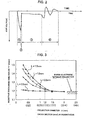
- FIG. 2 is a wave form of a discharge voltage in a discharge gap as shown in FIG. 1.
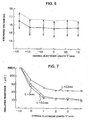
- FIG. 3 is a graph showing measurement result of inductive discharge time period "t".
- FIG. 4 is a table showing an evaluation result of an insulating resistance of each sample used on a vehicle which actually ran on road.
- FIG. 5 is a graph showing a lean limit of each sample.
- FIG. 6 is a graph showing a discharge voltage of each sample.
- FIG. 7 is a graph showing an insulating resistance of each sample used on a vehicle which actually ran on road.
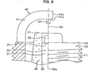
- FIG. 8 is a fragmentary cross sectional view of a main portion of the spark plug of Embodiment 2.
- FIG. 9 is a fragmentary cross sectional view of a main portion of the spark plug of Embodiment 3.
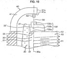
- FIG. 10 is a fragmentary cross sectional view of a main portion of the spark plug of Embodiment 4.
- FIG. 11 is a fragmentary cross sectional view of a main portion of the spark plug of Embodiment 5.
- FIG. 12 is a fragmentary cross sectional view of a main portion of the spark plug of Embodiment 6.
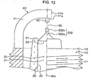
- FIG. 13 is a fragmentary cross sectional view of a main portion of the spark plug of Embodiment 7.
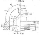
- FIG. 14 is a fragmentary cross sectional view of a main portion of the spark plug of Embodiment 8.
- FIG. 15 is a fragmentary cross sectional view of a main portion of the spark plug of Embodiment 9.
- FIG.1 is a fragmentary cross sectional view of a main portion of the spark plug of Embodiment 1, wherein a columnar hausing 10 (made of a conductive steel material such as a low carbon steel) is provided with a male screw 11 in order to fix the hausing 10 to a not-shown column head of an internal combustion engine.
- a columnar hausing 10 made of a conductive steel material such as a low carbon steel
- alumina ceramic Al 2 O 3
- the columnar central electrode 30 is fixed in an axial hole 22 of the insulator 20, thereby insulating the insulator 20 from the hausing 10.
- the inner material of the central electrode 30 is a highly heat conductive material such as Cu, while the outer material thereof is a highly heat resistant and corrosion resistant material such as a Ni base alloy, Fe base alloy, or Co base alloy.
- the central electrode 30 comprises: a columnar body 31 received in the insulator 20; and a narrowed portion 32 narrower than the body 31. Further, a border portion 33 between the body and narrowed portion 33 is disposed in the insulator 20, while the narrowed portion 32 extends from the body 31 toward a projection 42 of an earth electrode 40. The outer circumference of the border portion 33 forms an edge portion which is a starting point of the leak current.
- the end surface 12 of the hausing 10 is connected with the earth electrode 40 which comprises: a leg 41 welded to the hausing 10; and a projection 42 welded to the leg 41.
- the leg 41 is a square pillar made of a Ni base alloy, an end thereof is welded to the hausing 10, is then bent like a nearly L shape and other end thereof is opposite against the narrowed portion 32.
- a surface 41a of the leg 41 opposite to the narrowed portion 32 is nearly parallel to the reference plane which is perpendicular to an axis 30a of the central electrode.
- the projection 42 whose cross section is smaller than that of the leg 41 is joined to the surface 41a of the leg 41 and is projected from the leg 41 toward the narrowed portion 32.
- the projection 42 is opposite to the narrowed portion 32 at a discharge gap 50.
- the projection 42 is a column made of a noble metal such as a Pt alloy or Ir alloy. Further, the projection 42 may be joined to an end surface 41b.
- FIG. 2 is a waveform of a discharge voltage at the discharge gap 50, wherein a voltage between 10 kV and 20 kV is usually applied between the electrode 30 and electrode 40 during a high voltage applying period 1 ⁇ .
- the capacitive discharge is caused during a capacitive discharge period 2 ⁇ .
- a voltage between 0.5 kV and 1 kV is usually applied in order to maintain the inductive discharge during an inductive discharge period 3 ⁇ .
- a voltage between 0.5 kV and several kV is generated during a coil energy emission period 4 ⁇ when an energy still left in an ignition coil even under the discharge is consumed in the ignition coil.
- the inductive discharge time periods "t" were averaged over 1,000 discharges in the sample plugs with an ignition coil generally used for an automobile in a 0.4 Mpa chamber.
- FIG. 3 is a graph of the inductive discharge time period "t" vs. the diameters D of the projection 42 of which cross section is also denoted in parenthesis. As shown in FIG. 3, "t" becomes longer, when L is longer than or equal to 0.3 mm and D is smaller than or equal to 1.2 mm ( the cross section is smaller than or equal to 1.13 mm 2 ).
- the sample plugs with the length L of the projection 42 longer than 1.5 mm and the diameter D of the projection 42 smaller than 0.3 mm (cross section smaller than 0.07 mm 2 ) are not suitable for practical use, because they are not heat resistant due to easy wearing out of the projection 42.
- Sample spark plugs with various lengths L diameters D of the projection 42 were prepared, where the diameter "d" of the narrowed portion 32 of the central electrode 30 is 0.7 mm, the discharge gap 50 is 1.1 mm and the length A from the end surface 21 of the insulator 20 to the border portion 33 is 0.8 mm.
- FIG. 4 shows a test result, where " ⁇ " denotes that the insulating resistances were greater than 10 mega-ohms, while “ ⁇ ” denotes that the insulating resistances were smaller than 10 mega-ohms.
- the insulating resistances were maintained greater than 10 mega-ohms, thereby improving the carbon fouling burning-down effect due to the extended inductive discharge time period "t".
- the length "l" of the narrowed portion 32 projected from insulator end surface 21 was greater than or equal to zero and smaller than or equal to 1.0 mm in order to ensure the ignition capability and the discharge capability.
- FIG. 5 shows a evaluation result of the ignition capability of sample spark plugs with various length "l" of the narrowed portion 32.
- FIG. 6 shows a evaluation result of the discharge voltage.
- the end surface of the narrowed portion 32 with the minus "1" is positioned inside the insulator 20.
- the sample spark plug was of diameter "d" 0.7 mm, discharge gap 1.1 mm, length A 0.8 mm, length L 0.8 mm and diameter D 0.5 mm
- the ignition capability was evaluated by the lean limit in air-fuel (A/F) ratio at 800 rpm by the 4- cylinder 1600 cc engine. Further, the discharge voltage was evaluated by the average, maximum and minimum of 1,000 discharges in a 0.4 MPa chamber.
- both the ignition capability and discharge capability were allowable for "l" greater or equal to minus 1 mm. This is because the flame cooling at an early stage burning at the earth electrode is reduced, due to the projection 42 with a small diameter.
- the similar allowable results were obtained for the projection of L between 0.3 mm and 1.5 mm, both inclusive, and D between 0.3 mm and 1.2 mm, both inclusive.
- the length "l" of the narrowed portion 32 was smaller than or equal to 1.0 mm in order to ensure the carbon burning-down capability.
- FIG. 7 shows the insulating resistance between central the electrode 30 and earth electrode 40 with various lengths L of the projection 42 and "l" of the narrowed portion 32.
- the sample spark plugs were of diameter "d" 0.7 mm, discharge gap 1.1 mm, length A 0.8 mm, length L 0.8 mm and diameter D 0.5 mm.
- the insulating resistances between the electrode 30 and electrode 40 were measured after a 10 minute continuous rotation at 1200 rpm of 4-cylinder 1600 cc engine without load under dense air-fuel mixture atmosphere of A/F 10.0.
- the insulating resistances were maintained high enough to obtain a carbon burning-down capability allowable for practical use for the length L of the projection 42 greater than or equal to 0.3 mm, even when the length "l" of the narrowed portion 32 is greater than or equal to 1.0 mm.
- the inductive discharge following the capacitive discharge is utilized in order to burn down the carbon fouling in the already cited Japanese Patents No. 2727558 and 2805781. Further, the voltage applied during the inductive discharge is effectively utilized in the present invention, when length "l" of the narrowed portion 32 is long.
- the length "l" is preferably smaller than 2 mm, taking into consideration the thermal resistance of the narrowed portion 32.
- FIG. 8 shows Embodiment 2, wherein the tip surface of the narrowed portion 32 is positioned in the insulator 20, thereby burning down the carbon fouling adhered on the insulator 20 near the tip of the narrowed portion 32 by the sparks generated between the tip of the narrowed portion 32 and the projection 42.
- the burning-down effect is further improved.
- FIG. 9 shows Embodiment 3, wherein a form of the leg 141 of the earth electrode 40 is different from that in Embodiment 1.
- the surface 141a opposite to the narrowed portion 32 was made nearly parallel to the reference surface perpendicular to the axis 30a.
- the surface 141a is made tilted to the reference surface, thereby improving heat conductivity due to a shortened length of the leg 41.
- FIG. 10 shows Embodiment 4, wherein the multistage narrowed portion 132 is different from the narrowed portion 32 in Embodiment 1.
- the multistage narrowed portion 132 is made narrower by a plurality of stages from the body 31 toward the projection 42.
- the multistage narrowed portion 132 comprises: a tapered member 132a of which cross section is continuously decreased; a first column 132b extending from the tapered member 132a (of which diameter is smaller than that of the body 31) extending from the tapered member 132a; and a second column 132c (of which diameter is smaller than that of the first column 132b) extending from the first column 132b toward the projection 42.
- a border portion 33' between the first column 132b and the second column 132c is positioned in the insulator 20. Therefore, the border portion 33' is also a starting point of the leak current.
- the ionization by the leak current before the capacitive discharge is not only further ensured, but also the carbon burning-down effect is further improved due to the increased inductive discharge energy and extended inductive discharge time period.
- FIG. 11 shows Embodiment 5. Similar reference numerals designate the corresponding portions in Embodiment 1. The explanations thereof are omitted.
- the narrowed portion 232 comprises: a tapered member 232a of which cross section is continuously decreased from the body 31 toward the projection 42; and a column 232b (of which diameter is smaller than that of the body 31) extending from the tapered member 232a toward the projection 42.
- an axial hole 122 of the insulator 20 comprises: a first axial hole 122a for receiving the body 31; a tapered member 122b of which diameter is continuously decreased ftom the first axial hole toward end surface 21 ; and a second axial hole 122c (of which diameter is smaller than that of the first axial hole 122a) extending from the tapered member 122b toward the end surface 21 of the insulator 20.
- FIG. 12 Shows Embodiment 6, wherein the narrowed portion 132 in Embodiment 4 as shown in FIG. 10 and the axial hole 122 in Embodiment 5 as shown in FIG. 11 are employed.
- FIG. 13 shows Embodiment 7, wherein the narrowed portion 332 is different from thast in Embodiment 1.
- the narrowed portion 332 comprises: a tapered member 332a of which cross section is continuously decreased from the body 31 toward the projection; and a column 332b (of which diameter is smaller than that of the body 31) extending from the tapered member 332a toward the projection 42.
- FIG. 14 shows Embodiment 8, wherein the narrowed portion 332 in Embodiment 7 as shown FIG. 13 and the leg 141 as shown in FIG. 9 are employed.
- FIG. 15 shows Embodiment 9, wherein a form of the narrowed portion 432 is different from that in Embodiment 1.
- the narrowed portion 432 is narrowed a plurality of times from the body 31 toward the projection 42.
- the narrowed portion 432 comprises: a first tapered member 432a of which cross section is continuously decreased from the body toward the projection; a first column 432b (of which diameter is smaller than that of the body 31) extending from the first tapered member 432a toward the projection 42; a second tapered member 432c of which cross section is continuously decreased from the first column 432b toward the projection 42; and a second column 432d (of which diameter is smaller than that of the first column 432b) extending from the second tapered member 432c toward the projection 42.
- a border portion 33' between the first column 432b and the second tapered member 432c is positioned in the insulator 20. Therefore, the border portion 33' is also a starting point of the leak current.
- the ionization by the leak current before the capacitive discharge is not only further ensured, but also the carbon burning-down effect is further improved due to the increased inductive discharge energy and extended inductive discharge time period.
- the projection 42 was a column in the above-mentioned Embodiments, the cross section of the projection 42 may be a square, rhomb, ellipse, or rectangle.
- the projection 42 of the earth electrode 40 was made of noble metal
- the narrowed portion 32, 132c, 232b, 332b and 432d may be made of noble metal.
- narrowed portion 32, 132c, 232b, 332b and 432d and the projection 42 of the earth electrode 40 may be made of one of Pt-Ir, Pt-Rh, Pt-Ni, Ir-Rh, or Ir-Y.
- the narrowed portion 32, 132c, 232b, 332b and 432d and the projection 42 of the earth electrode 40 may be made of a Pt alloy in which at least one of Ir, Ni, Rh, W, Pd, Ru, Os is added. More concretely, the Pt alloy in which at least one of less than or equal to 50 wt.% Ir, less than or equal to 40 wt.% Ni, less than or equal to 50 wt. % Rh, less than or equal to 30 wt.% W, less than or equal to 40 wt.% Pd, less than or equal to 30 wt.% Ru, or less than or equal to 20 wt. % Os may be employed.
- the narrowed portion 32, 132c, 232b, 332b and 432d and the projection 42 of the earth electrode 40 may be made of an Ir alloy in which at least one of Rh, Pt, Ni, W, Pd, Ru, Os is added. More concretely, the Ir alloy in which at least one of less than or equal to 50 wt.% Rh, less than or equal to 50 wt.% Pt, less than or equal to 40 wt.% Ni, less than or equal to 30 wt.% W, less than or equal to 40 wt.% Pd, less than or equal to 30 wt.% Ru, or less than or equal to 20 wt. % Os may be employed.
- Carbon fouling adhered on an insulator tip of a spark plug of the present invention is burnt down by a leak current during an inductive discharge period, due to a promoted ionization before beginning a capacitive discharge, in such an arrangement of a central electrode that a border portion of a body and narrowed portion is positioned in an insulator.
- the carbon burning-down effect is further improved by a narrow projection provided with an earth electrode, due to increased inductive energy and extended inductive discharge time period. This is because an electric field in a discharge gap is raised, thereby decreasing a discharge voltage and suppressing an energy emitted from a coil during the capacitive discharge.
Landscapes
- Spark Plugs (AREA)
- Ignition Installations For Internal Combustion Engines (AREA)
Abstract
Description
Claims (15)
- A spark plug for an internal combustion engine comprising;
a columnar central electrode;
an insulator for holding said central electrode ;
a hausing for holding said insulator;
an earth electrode wherein one end thereof is connected with said hausing and the other end thereof is opposite to said central electrode,
wherein:said earth electrode has a leg connected with said hausing and a projection smaller than said leg which projects from said leg toward said central electrode;said central electrode has a body held in said insulator and a narrowed portion smaller than said body which projects from said body toward said projection; anda first border portion (33) between said body and narrowed portion is positioned in said insulator. - The spark plug according to claim 1, which further comprises a second border portion (33') between said body and narrowed portion is positioned in said insulator.
- The spark plug according to claim 1, wherein a surface of said earth electrode opposite to said central electrode is tilted from a surface perpendicular to an axis of said central electrode.
- The spark plug according to claim 1, wherein a cross section of said projection is between 0.07 and 1.13 mm2, both inclusive.
- The spark plug according to claim 1, wherein a length of said projection from said leg is between 0.3 and 1.5 mm, both inclusive.
- The spark plug according to claim 1, wherein said projection is made of noble metal material.
- The spark plug according to claim 6, wherein said noble metal material is a Pt alloy or Ir alloy.
- The spark plug according to claim 1, wherein said first border portion is positioned between 0.1 mm and 1.2 mm, both inclusive, from an end surface of said insulator.
- The spark plug according to claim 2, wherein said second border portion is positioned between 0.1 mm and 1.2 mm, both inclusive, from an end surface of said insulator.
- The spark plug according to claim 1, wherein said narrowed portion is narrowed a plurality of times from said body toward said projection.
- The spark plug according to claim 1, wherein said narrowed portion includes a tapered member of which cross section is continuously decreased from said body toward said projection.
- The spark plug according to claim 1, wherein a tip of said narrowed portion is positioned between-1 mm and + 2 mm, both inclusive, from an end surface of said insulator.
- The spark plug according to claim 12, wherein said tip of said narrowed portion is positioned in said insulator.
- The spark plug according to claim 1, wherein said narrowed portion is made of noble metal material.
- The spark plug according to claim 14, wherein said noble metal material is a Pt alloy or Ir alloy.
Applications Claiming Priority (4)
| Application Number | Priority Date | Filing Date | Title |
|---|---|---|---|
| JP2002108073 | 2002-04-10 | ||
| JP2002108073 | 2002-04-10 | ||
| JP2003027155A JP2004006250A (en) | 2002-04-10 | 2003-02-04 | Spark plug for internal combustion engine |
| JP2003027155 | 2003-02-04 |
Publications (3)
| Publication Number | Publication Date |
|---|---|
| EP1353423A2 true EP1353423A2 (en) | 2003-10-15 |
| EP1353423A3 EP1353423A3 (en) | 2006-10-04 |
| EP1353423B1 EP1353423B1 (en) | 2009-12-23 |
Family
ID=28456381
Family Applications (1)
| Application Number | Title | Priority Date | Filing Date |
|---|---|---|---|
| EP03008267A Expired - Lifetime EP1353423B1 (en) | 2002-04-10 | 2003-04-09 | Spark plug for internal combustion engine |
Country Status (5)
| Country | Link |
|---|---|
| US (1) | US7105990B2 (en) |
| EP (1) | EP1353423B1 (en) |
| JP (1) | JP2004006250A (en) |
| CN (1) | CN100355165C (en) |
| DE (1) | DE60330618D1 (en) |
Cited By (3)
| Publication number | Priority date | Publication date | Assignee | Title |
|---|---|---|---|---|
| US7541724B2 (en) | 2005-04-01 | 2009-06-02 | Denso Corporation | Spark plug requiring low discharge voltage and having high self-cleaning capability |
| EP2581999A4 (en) * | 2010-06-11 | 2014-01-08 | Ngk Spark Plug Co | IGNITION CANDLE |
| US9391429B2 (en) | 2011-09-28 | 2016-07-12 | Robert Bosch Gmbh | Spark plug |
Families Citing this family (17)
| Publication number | Priority date | Publication date | Assignee | Title |
|---|---|---|---|---|
| US7352121B2 (en) * | 2003-09-26 | 2008-04-01 | Ngk Spark Plug Co., Ltd. | Spark plug |
| US7615915B2 (en) * | 2003-09-26 | 2009-11-10 | Ngk Spark Plug Co., Ltd. | Spark plug |
| US7291961B2 (en) * | 2003-09-27 | 2007-11-06 | Ngk Spark Plug Co., Ltd. | Spark plug having a specific structure of noble metal tip on ground electrode |
| EP1519459B1 (en) | 2003-09-27 | 2010-12-08 | NGK Spark Plug Company Limited | Spark plug |
| US7187110B2 (en) * | 2003-09-27 | 2007-03-06 | Ngk Spark Plug Co., Ltd. | Spark plug |
| US20050168121A1 (en) | 2004-02-03 | 2005-08-04 | Federal-Mogul Ignition (U.K.) Limited | Spark plug configuration having a metal noble tip |
| JP4604803B2 (en) * | 2005-04-05 | 2011-01-05 | 株式会社デンソー | Exhaust treatment device |
| JP4930201B2 (en) * | 2007-06-01 | 2012-05-16 | トヨタ自動車株式会社 | Internal combustion engine spark plug |
| JP4692588B2 (en) * | 2007-07-31 | 2011-06-01 | 株式会社デンソー | Spark plug for internal combustion engine and method for manufacturing the same |
| WO2009087894A1 (en) * | 2008-01-10 | 2009-07-16 | Ngk Spark Plug Co., Ltd. | Spark plug for internal combustion engine and method of manufacturing the same |
| DE112012002688B4 (en) | 2011-06-28 | 2021-08-12 | Federal-Mogul Ignition LLC (n. d. Ges. d. Staates Delaware) | Spark plugs and processes for their manufacture |
| JP5887785B2 (en) * | 2011-09-17 | 2016-03-16 | 株式会社デンソー | Spark plug and ignition device |
| DE112012003972B4 (en) | 2011-09-23 | 2019-05-23 | Federal-Mogul Ignition Company | Spark plug and ground electrode manufacturing process |
| JP6311499B2 (en) * | 2014-07-02 | 2018-04-18 | 株式会社デンソー | Spark plug for internal combustion engine |
| JP6759864B2 (en) | 2016-08-30 | 2020-09-23 | 株式会社デンソー | Spark plug |
| JP6702094B2 (en) | 2016-08-31 | 2020-05-27 | 株式会社デンソー | Spark plug |
| JP6780381B2 (en) | 2016-08-31 | 2020-11-04 | 株式会社デンソー | Spark plugs and their manufacturing methods |
Family Cites Families (12)
| Publication number | Priority date | Publication date | Assignee | Title |
|---|---|---|---|---|
| US4700103A (en) * | 1984-08-07 | 1987-10-13 | Ngk Spark Plug Co., Ltd. | Spark plug and its electrode configuration |
| JP2805781B2 (en) | 1988-12-29 | 1998-09-30 | 株式会社デンソー | Spark plug for internal combustion engine |
| JP2727558B2 (en) | 1987-04-16 | 1998-03-11 | 株式会社デンソー | Spark plug for internal combustion engine |
| DE3872027T2 (en) * | 1987-04-16 | 1993-01-21 | Nippon Denso Co | SPARK PLUG FOR COMBUSTION ENGINE. |
| US5159232A (en) * | 1987-04-16 | 1992-10-27 | Nippondenso Co., Ltd. | Spark plugs for internal-combustion engines |
| JP2877035B2 (en) * | 1995-06-15 | 1999-03-31 | 株式会社デンソー | Spark plug for internal combustion engine |
| JP3272615B2 (en) * | 1995-11-16 | 2002-04-08 | 日本特殊陶業株式会社 | Spark plug for internal combustion engine |
| CA2291351C (en) * | 1998-12-04 | 2004-03-16 | Denso Corporation | Spark plug for internal combustion engine having better self-cleaning function |
| JP3980279B2 (en) | 2000-02-16 | 2007-09-26 | 日本特殊陶業株式会社 | Spark plug |
| JP2001345162A (en) * | 2000-03-30 | 2001-12-14 | Denso Corp | Spark plug for internal combustion engine |
| JP4305713B2 (en) * | 2000-12-04 | 2009-07-29 | 株式会社デンソー | Spark plug |
| JP2003317896A (en) * | 2002-02-19 | 2003-11-07 | Denso Corp | Spark plug |
-
2003
- 2003-02-04 JP JP2003027155A patent/JP2004006250A/en active Pending
- 2003-04-08 CN CNB031102549A patent/CN100355165C/en not_active Expired - Lifetime
- 2003-04-08 US US10/408,089 patent/US7105990B2/en not_active Expired - Lifetime
- 2003-04-09 EP EP03008267A patent/EP1353423B1/en not_active Expired - Lifetime
- 2003-04-09 DE DE60330618T patent/DE60330618D1/en not_active Expired - Lifetime
Cited By (4)
| Publication number | Priority date | Publication date | Assignee | Title |
|---|---|---|---|---|
| US7541724B2 (en) | 2005-04-01 | 2009-06-02 | Denso Corporation | Spark plug requiring low discharge voltage and having high self-cleaning capability |
| EP2581999A4 (en) * | 2010-06-11 | 2014-01-08 | Ngk Spark Plug Co | IGNITION CANDLE |
| US9391429B2 (en) | 2011-09-28 | 2016-07-12 | Robert Bosch Gmbh | Spark plug |
| EP2761710B1 (en) * | 2011-09-28 | 2016-10-12 | Robert Bosch GmbH | Improved spark plug |
Also Published As
| Publication number | Publication date |
|---|---|
| JP2004006250A (en) | 2004-01-08 |
| US7105990B2 (en) | 2006-09-12 |
| EP1353423A3 (en) | 2006-10-04 |
| EP1353423B1 (en) | 2009-12-23 |
| US20030193282A1 (en) | 2003-10-16 |
| CN100355165C (en) | 2007-12-12 |
| DE60330618D1 (en) | 2010-02-04 |
| CN1450697A (en) | 2003-10-22 |
Similar Documents
| Publication | Publication Date | Title |
|---|---|---|
| EP1353423B1 (en) | Spark plug for internal combustion engine | |
| EP1211767B1 (en) | Spark plug and method for manufacturing the same | |
| EP2216862B1 (en) | Spark plug | |
| US5502351A (en) | Spark plug having horizontal discharge gap | |
| KR101375915B1 (en) | Spark plug | |
| JPWO2021111719A1 (en) | Spark plug | |
| US6208066B1 (en) | Semi-creeping discharge type spark plug | |
| US7122948B2 (en) | Spark plug having enhanced capability to ignite air-fuel mixture | |
| KR101118401B1 (en) | Spark plug | |
| JP6645314B2 (en) | Spark plug for internal combustion engine and method of manufacturing the same | |
| US9482203B2 (en) | Spark plug for internal combustion engines and mounting structure for the spark plug | |
| KR20110079709A (en) | Spark plug | |
| US8884504B2 (en) | Spark plug for internal combustion engines and mounting structure for the spark plug | |
| JP2004022450A (en) | Spark plug for internal combustion engine | |
| JP3796845B2 (en) | Spark plug | |
| EP0376147A1 (en) | Spark plugs for internal-combustion engines | |
| JP4377177B2 (en) | Spark plug for internal combustion engine | |
| JPH07272826A (en) | Spark plug | |
| JPH09266056A (en) | Spark plug | |
| JP2006073205A (en) | Spark plug | |
| JP2006253160A (en) | Spark plug for internal combustion engine | |
| JPH0350393B2 (en) | ||
| JPS6062083A (en) | Ignition plug of internal combustion engine | |
| JPH0350394B2 (en) | ||
| JP2006260988A (en) | Spark plug |
Legal Events
| Date | Code | Title | Description |
|---|---|---|---|
| PUAI | Public reference made under article 153(3) epc to a published international application that has entered the european phase |
Free format text: ORIGINAL CODE: 0009012 |
|
| AK | Designated contracting states |
Kind code of ref document: A2 Designated state(s): AT BE BG CH CY CZ DE DK EE ES FI FR GB GR HU IE IT LI LU MC NL PT SE SI SK TR |
|
| AX | Request for extension of the european patent |
Extension state: AL LT LV MK RO |
|
| PUAL | Search report despatched |
Free format text: ORIGINAL CODE: 0009013 |
|
| AK | Designated contracting states |
Kind code of ref document: A3 Designated state(s): AT BE BG CH CY CZ DE DK EE ES FI FR GB GR HU IE IT LI LU MC NL PT SE SI SK TR |
|
| AX | Request for extension of the european patent |
Extension state: AL LT LV MK RO |
|
| 17P | Request for examination filed |
Effective date: 20070402 |
|
| AKX | Designation fees paid |
Designated state(s): DE FR GB |
|
| GRAP | Despatch of communication of intention to grant a patent |
Free format text: ORIGINAL CODE: EPIDOSNIGR1 |
|
| GRAS | Grant fee paid |
Free format text: ORIGINAL CODE: EPIDOSNIGR3 |
|
| GRAA | (expected) grant |
Free format text: ORIGINAL CODE: 0009210 |
|
| AK | Designated contracting states |
Kind code of ref document: B1 Designated state(s): DE FR GB |
|
| REG | Reference to a national code |
Ref country code: GB Ref legal event code: FG4D |
|
| REF | Corresponds to: |
Ref document number: 60330618 Country of ref document: DE Date of ref document: 20100204 Kind code of ref document: P |
|
| PLBE | No opposition filed within time limit |
Free format text: ORIGINAL CODE: 0009261 |
|
| STAA | Information on the status of an ep patent application or granted ep patent |
Free format text: STATUS: NO OPPOSITION FILED WITHIN TIME LIMIT |
|
| 26N | No opposition filed |
Effective date: 20100924 |
|
| REG | Reference to a national code |
Ref country code: FR Ref legal event code: PLFP Year of fee payment: 13 |
|
| REG | Reference to a national code |
Ref country code: FR Ref legal event code: PLFP Year of fee payment: 14 |
|
| REG | Reference to a national code |
Ref country code: FR Ref legal event code: PLFP Year of fee payment: 15 |
|
| REG | Reference to a national code |
Ref country code: FR Ref legal event code: PLFP Year of fee payment: 16 |
|
| PGFP | Annual fee paid to national office [announced via postgrant information from national office to epo] |
Ref country code: GB Payment date: 20220420 Year of fee payment: 20 Ref country code: FR Payment date: 20220420 Year of fee payment: 20 Ref country code: DE Payment date: 20220420 Year of fee payment: 20 |
|
| REG | Reference to a national code |
Ref country code: DE Ref legal event code: R071 Ref document number: 60330618 Country of ref document: DE |
|
| REG | Reference to a national code |
Ref country code: GB Ref legal event code: PE20 Expiry date: 20230408 |
|
| PG25 | Lapsed in a contracting state [announced via postgrant information from national office to epo] |
Ref country code: GB Free format text: LAPSE BECAUSE OF EXPIRATION OF PROTECTION Effective date: 20230408 |