EP1353413A1 - Lever for removing electric apparatus - Google Patents
Lever for removing electric apparatus Download PDFInfo
- Publication number
- EP1353413A1 EP1353413A1 EP03005625A EP03005625A EP1353413A1 EP 1353413 A1 EP1353413 A1 EP 1353413A1 EP 03005625 A EP03005625 A EP 03005625A EP 03005625 A EP03005625 A EP 03005625A EP 1353413 A1 EP1353413 A1 EP 1353413A1
- Authority
- EP
- European Patent Office
- Prior art keywords
- lever
- electric apparatus
- connector
- base
- view
- Prior art date
- Legal status (The legal status is an assumption and is not a legal conclusion. Google has not performed a legal analysis and makes no representation as to the accuracy of the status listed.)
- Granted
Links
- 238000005304 joining Methods 0.000 claims abstract description 3
- 238000007373 indentation Methods 0.000 description 16
- 239000002184 metal Substances 0.000 description 13
- 238000005192 partition Methods 0.000 description 10
- 238000003860 storage Methods 0.000 description 7
- 230000007246 mechanism Effects 0.000 description 6
- 230000003014 reinforcing effect Effects 0.000 description 5
- 238000000034 method Methods 0.000 description 4
- 230000004048 modification Effects 0.000 description 3
- 238000012986 modification Methods 0.000 description 3
- 238000005452 bending Methods 0.000 description 2
- 230000000630 rising effect Effects 0.000 description 2
- 230000009471 action Effects 0.000 description 1
- 230000008901 benefit Effects 0.000 description 1
- 230000015572 biosynthetic process Effects 0.000 description 1
- 238000005520 cutting process Methods 0.000 description 1
- 230000002950 deficient Effects 0.000 description 1
- 230000005489 elastic deformation Effects 0.000 description 1
- 230000005484 gravity Effects 0.000 description 1
- 238000009413 insulation Methods 0.000 description 1
- 238000004519 manufacturing process Methods 0.000 description 1
- 230000002093 peripheral effect Effects 0.000 description 1
- 230000008569 process Effects 0.000 description 1
- 239000011347 resin Substances 0.000 description 1
- 229920005989 resin Polymers 0.000 description 1
Images









Classifications
-
- H—ELECTRICITY
- H01—ELECTRIC ELEMENTS
- H01R—ELECTRICALLY-CONDUCTIVE CONNECTIONS; STRUCTURAL ASSOCIATIONS OF A PLURALITY OF MUTUALLY-INSULATED ELECTRICAL CONNECTING ELEMENTS; COUPLING DEVICES; CURRENT COLLECTORS
- H01R13/00—Details of coupling devices of the kinds covered by groups H01R12/70 or H01R24/00 - H01R33/00
- H01R13/62—Means for facilitating engagement or disengagement of coupling parts or for holding them in engagement
- H01R13/629—Additional means for facilitating engagement or disengagement of coupling parts, e.g. aligning or guiding means, levers, gas pressure electrical locking indicators, manufacturing tolerances
- H01R13/62933—Comprising exclusively pivoting lever
- H01R13/62955—Pivoting lever comprising supplementary/additional locking means
-
- H—ELECTRICITY
- H01—ELECTRIC ELEMENTS
- H01R—ELECTRICALLY-CONDUCTIVE CONNECTIONS; STRUCTURAL ASSOCIATIONS OF A PLURALITY OF MUTUALLY-INSULATED ELECTRICAL CONNECTING ELEMENTS; COUPLING DEVICES; CURRENT COLLECTORS
- H01R13/00—Details of coupling devices of the kinds covered by groups H01R12/70 or H01R24/00 - H01R33/00
- H01R13/62—Means for facilitating engagement or disengagement of coupling parts or for holding them in engagement
- H01R13/629—Additional means for facilitating engagement or disengagement of coupling parts, e.g. aligning or guiding means, levers, gas pressure electrical locking indicators, manufacturing tolerances
- H01R13/633—Additional means for facilitating engagement or disengagement of coupling parts, e.g. aligning or guiding means, levers, gas pressure electrical locking indicators, manufacturing tolerances for disengagement only
- H01R13/6335—Additional means for facilitating engagement or disengagement of coupling parts, e.g. aligning or guiding means, levers, gas pressure electrical locking indicators, manufacturing tolerances for disengagement only comprising a handle
-
- H—ELECTRICITY
- H01—ELECTRIC ELEMENTS
- H01R—ELECTRICALLY-CONDUCTIVE CONNECTIONS; STRUCTURAL ASSOCIATIONS OF A PLURALITY OF MUTUALLY-INSULATED ELECTRICAL CONNECTING ELEMENTS; COUPLING DEVICES; CURRENT COLLECTORS
- H01R9/00—Structural associations of a plurality of mutually-insulated electrical connecting elements, e.g. terminal strips or terminal blocks; Terminals or binding posts mounted upon a base or in a case; Bases therefor
- H01R9/22—Bases, e.g. strip, block, panel
- H01R9/24—Terminal blocks
- H01R9/26—Clip-on terminal blocks for side-by-side rail- or strip-mounting
- H01R9/2625—Clip-on terminal blocks for side-by-side rail- or strip-mounting with built-in electrical component
-
- H—ELECTRICITY
- H01—ELECTRIC ELEMENTS
- H01R—ELECTRICALLY-CONDUCTIVE CONNECTIONS; STRUCTURAL ASSOCIATIONS OF A PLURALITY OF MUTUALLY-INSULATED ELECTRICAL CONNECTING ELEMENTS; COUPLING DEVICES; CURRENT COLLECTORS
- H01R9/00—Structural associations of a plurality of mutually-insulated electrical connecting elements, e.g. terminal strips or terminal blocks; Terminals or binding posts mounted upon a base or in a case; Bases therefor
- H01R9/22—Bases, e.g. strip, block, panel
- H01R9/24—Terminal blocks
- H01R9/26—Clip-on terminal blocks for side-by-side rail- or strip-mounting
- H01R9/2683—Marking plates or tabs
Definitions
- a U-shaped pocket 20 is prepared, as shown in Fig. 7 for collecting scraps of lead lines which may be generated when the lead lines are forcibly pulled out.
- a storage space 21 is prepared for a clamp spring 49.
- Fig. 3 also shows that the bottom surface of the base 11 on the opposite side is further provided with a latch part 37 parallel to and at a specified distance from the aforementioned protrusion 36.
- This latch part 37 is provided with a reinforcing rib 37a and a protrusion 37b near by for preventing rattling when it is mounted onto the rail.
- the latch part 37 on the base 11 is engaged to one of the edge parts of the rail and the connector 10 as a whole is pressed against the rail.
- the straight leg parts 33 and the arched leg part 34 are elastically deformed, they are returned to their original positions.
- the elongated downward protrusion 36 comes into contact with the other side edge of the rail and the protrusion 35d of the elastic hook 32 becomes engaged with the other side edge of the rail. The attachment to the rail is thus concluded.
- the handling bar 80 For removing an inserted lead line, the handling bar 80 is inserted into the handling bar hole 16 along the guide surface 16a so as to compress and elastically deform the clamp spring 49 and to thereby release the clamping force on the lead line.
- the lead line is thereafter pulled out through the connection hole 49a of the clamp spring 49 and the handling bar 80 is thereafter pulled out.
- Figs. 16-19 relate to a second embodiment of this invention relating to a connector 10 for mounting a two-pole relay.
- continuous guide surfaces16a and 55a are formed in the handling bar holes 16 and 55 of its base 11 and case 50 for guiding the handling bar 80 to a desired position.
- Partition walls 16 with protrusions 59a are provided inside the case 50, as shown in Fig. 16 and engaging holes 11a are formed in the base 11 such that, as the protrusions 59a are inserted into the engaging holes 11a, the case 50 is prevented from warping outward and no gap is generated between the inner side surfaces of the case 50 and the outer side surfaces of the base 11.
- the structure is formed so as not to allow scraps of lead lines from falling off through such a gap.
- the structure is similar to the first embodiment and hence the description will be omitted.
- Figs. 22 and 23 show a fifth embodiment of the invention intended to improve resistance of the lever 60 against vibrations and impact forces so as to prevent the mounted relay 70 from rattling or falling off.
- the lever 60 according to this invention is provided with an engaging latch 66a at the tip of an elongated member 66 extending away from the rotary shaft 62 for limiting the rotary action.
- a guide area 66b is formed on the outwardly facing surface of the engaging latch 66a for guiding the handling bar (not shown) which is used for unlocking the latch 66a.
- Such an engaging latch may be provided elsewhere. For example, it may be provided on the horizontal arm 63 of the main body 61. It may be hooked to the base 11 of the housing.
Landscapes
- Details Of Connecting Devices For Male And Female Coupling (AREA)
Abstract
Description
- This invention relates to a lever for use in particular for removing an electric apparatus such as a relay or a timer that is connected to a connector for such an electric apparatus.
- Fig. 24A shows an example of prior art lever 1 for removing an
electric apparatus 5 from thehousing 9 of a connector into which it is inserted, having a generally L-shaped main body 2 as seen from the front.Rotary shafts 3 protruding coaxially from both side surfaces of this lever main body 2 at its angle-forming part are inserted into thehousing 9 so as to rotatably support the lever 1. When it is desired to remove theapparatus 5 from thehousing 9, the lever 1 is rotated such that thehorizontal arm 4 of its main body 2 pushes up the bottom surface of theapparatus 5 to remove it from thehousing 9. Since theapparatus 5 is pushed only at one point on its bottom surface, as shown in Fig. 24B, however, theapparatus 5 is tilted during the process of its removal, and it cannot be removed smoothly. If theapparatus 5 is tilted by an angle that is too large, in particular, the transverse force exerted on itsterminals 6 may become too large and cause them to be bent or broken. - It is therefore an object of this invention, in view of the problem with such a prior art lever, to provide an improved lever capable of removing an electric apparatus smoothly from a connector housing without bending or breaking the terminals of the apparatus.
- A lever according to this invention, with which the above and other objects can be accomplished, may be characterized as comprising not only a generally L-shaped main body having a horizontal arm and a vertical arm joining at an angle-forming part, rotary shafts which protrude coaxially from this angle-forming part to be rotatably supported by the connector such that the horizontal part lifts the mounted electric apparatus as the main body is rotated around these rotary shafts, but also a holding structure which extends from the horizontal arm in a direction away from the shafts and is adapted to come into contact with the surface of the electric apparatus facing away from the vertical arm when the main body is rotated by more than a certain specified angle. With the lever provided with such a holding structure, the electric apparatus being removed is prevented from tilting excessively with the holding structure coming into contact therewith such that the apparatus can be removed smoothly without causing its terminals to be bent and damaged. If this holding structure is in the form of a frame, its mechanical strength is improved and the electric apparatus being removed can be more dependably prevented from tilting excessively.
- As a variation, connecting arms may be provided for connecting the holding structure and the vertical arm of the lever. This has the advantage of reinforcing the extended holding structure. As a further variation, at least one latch may be provided beside the vertical part, say, on the aforementioned connecting arm for engaging with the electric apparatus for more dependably preventing the electric apparatus from floating up or falling off the housing structure.
- As still another variation, the vertical arm may be provided with an attachment part for a name plate near its top end. Such a name plate is convenient because various data may be written on.
-
- Fig. 1 is an exploded diagonal view of a connector including a lever embodying this invention for an electric apparatus.
- Figs. 2A, 2B and 2C, together referred to as Fig. 2, are diagonal views of the connector of Fig. 1 for showing how it is used.
- Fig. 3 is a longitudinal sectional view of the connector of Fig. 1.
- Figs. 4A, 4B and 4C, together referred to as Fig. 4, are respectively a diagonal view of the connector of Fig. 1 taken from a different angle, an enlarged diagonal view of its portion and a sectional view of a portion of Fig. 4A.
- Figs. 5A, 5B, 5C and 5D, together referred to as Fig. 5, are respectively a diagonal view of the case taken from a different direction, an enlarged portion of Fig. 5B, a diagonal view of the base taken from a different direction, and an enlarged portion of Fig. 5C.
- Figs. 6A, 6B, 6C and 6D, together referred to as Fig. 6, are respectively a front view of the connector of Fig. 1 when the case is being engaged to the base, a front view when the case has been engaged to the base, a sectional view taken along line 6C-6C of Fig. 6B and a sectional view taken along line 6D-6D of Fig. 6B.
- Figs. 7A, 7B, 7C, 7D and 7E, together referred to as Fig. 7, are enlarged views of a portion of the connector of Fig. 1 for showing how it is used with a handling bar.
- Figs. 8A, 8B, 8C and 8D, together referred to as Fig. 8, are respectively an enlarged diagonal view of a portion of the base shown in Fig. 1, its sectional view, an enlarged diagonal view of another base and its sectional view.
- Figs. 9A, 9B, 9C and 9D, together referred to as Fig. 9, are respectively an enlarged diagonal view of a portion of a different base, its sectional view, an enlarged diagonal view of a portion of still another base, and its sectional view.
- Figs. 10A, 10B, 10C, 10D, 10E and 10F, together referred to as Fig. 10, are drawings for explaining the shape of the handling bar hole, Figs. 10A and 10B being respectively a plan view and a diagonal view at an initial step of its formation, Figs. 10C and 10 D being respectively a plan view and a diagonal view at an intermediate step, and Figs. 10E and 10F being respectively a plan view and a diagonal view at a final step.
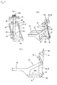
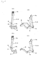
- Figs. 11A, 11B and 11C, together referred to as Fig. 11, show the lever of Fig. 1, Figs. 11A and 11B being its diagonal views and Fig. 11C being its front view.
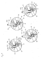
- Figs. 12A and 12B, together referred to as Fig. 12, are front views of the lever for showing its motion in operation.
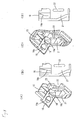
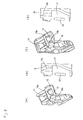
- Figs. 13A, 13B and 13C, together referred to as Fig. 13, are partially sectional views of the lever of Fig. 11 for showing the method of using it.
- Figs. 14A, 14B, 14C and 14D, together referred to as Fig. 14, are diagonal views of other levers embodying this invention.
- Figs. 15A, 15B, 15C and 15D, together referred to as Fig. 15, are diagonal views of still other levers embodying this invention.
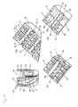
- Fig. 16A, 16B, 16C, 16E and 16F, together referred to as Fig. 16, show another connector with a lever embodying this invention, Fig. 16A being a diagonal view of its case, Fig. 16B being an enlarged view of a portion thereof, Fig. 16C being a diagonal view of its base, Fig. 16D being an enlarged view of a portion thereof, and Fig. 16E being a diagonal view of its base taken from a different direction.
- Figs. 17A, 17B, 17C, 17D and 17E, together referred to as Fig. 17, show the connector of Fig. 16, Fig. 17A being its partially sectional view, Fig. 17B being a diagonal view of a portion of the connector, Fig. 17C being a diagonal view of a portion of its base, and Fig. 17D being a diagonal view of a portion of its case.
- Figs. 18A, 18B and 18C, together referred to as Fig. 18, show the connector of Fig. 16, Fig. 18A being its front view when its case is being engaged to its base, Fig. 18B being its front view after its case has been engaged to its base, and Fig. 18C being a sectional view taken along line 18C-18C of Fig. 18B.
- Figs. 19A and 19B are respectively a bottom view and a diagonal view of the terminal shown in Fig. 16, and Fig. 19C is a diagonal view of a portion of another base.
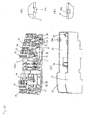
- Figs. 20A, 20B, 20C and 20D, together referred to as Fig. 20, show a connector according to a third embodiment of this invention, Fig. 20A being a diagonal view of its base, Fig. 20B being an enlarged view of a portion thereof, Fig. 20C being a diagonal view of its case, and Fig. 20D being an enlarged view of a portion thereof.
- Figs. 21A, 21B, 21C and 21D, together referred to as Fig. 21, show a connector according to a fourth embodiment of this invention, Fig. 21A being a diagonal view of its base, Fig. 21B being an enlarged view of a portion thereof, Fig. 21C being a diagonal view of its case, and Fig. 21D being an enlarged view of a portion thereof.
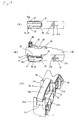
- Figs. 22A and 22B, together referred to as Fig. 22, show a connector according to a fifth embodiment of the invention, Fig. 22A being a diagonal view with a relay mounted thereto and Fig. 22B being an enlarged sectional view of a portion thereof.
- Figs. 23A, 23B and 23C, together referred to as Fig. 23, show the lever shown in Fig. 22, Fig. 23A being its diagonal view, Fig. 23B being its plan view and Fig. 23C being its longitudinal sectional view.
- Figs. 24A and 24B, together referred to as Fig. 24, are side views of a prior art connector for an electric apparatus for explaining the method of using it.
-
- Throughout herein, comparable or like components are indicated by the same numerals even where they are components of different connectors and may not be repetitiously described.
- The invention is described next with reference to Figs. 1-15 showing an example as applied to a connector 10 for mounting a one-pole relay. As shown in Fig. 1, this connector 10 is comprised of a
base 11, connectingmechanisms base 11, acase 50 which engages with thebase 11 and alever 60 which is rotatably attached toward one side of the upper surface of thebase 11. - The
base 11 is a molded resin product having a rail attachment mechanism 30 integrally formed on its bottom surface. Anindentation 12 for mounting therein a relay (shown at 70 in Figs. 2B and 2C) is formed in the middle on the top surface of thebase 11. Steps are formed on the top surface of theindentation 12 toward one side. Agroove 13 for inserting thelever 60 is formed at the bottom of theindentation 12, and a plurality of terminal-acceptingholes 14 for accepting the terminals 71 (shown in Fig. 13C) of therelay 70 are provided near thegroove 13. - Lead line holes 15 for inserting lead lines and handling bar holes 16 for inserting a handling
bar 80 are provided on the top surface of the base 11 on both sides of theindentation 12 at a specified pitch. As shown in Fig. 8, aguide surface 16a for guiding the handlingbar 80 is formed inside each handlingbar hole 16. Theguide surface 16a is formed by forming a taperedflat surface 16b as shown in Figs. 10C and 10D inside a sectionally octagonalstraight hole 16 shown in Figs. 10A and 10B and then cutting the taperedsurface 16b as shown in Figs. 10E and 10F. Theguide surface 16a is not required to extend to the bottom opening of thehole 16 but may extend only partially, as shown in Figs. 8C and 8D. Alternatively, as shown in Figs. 9A and 9B, theguide surface 16a may be formed with a curved surface. As shown in Figs. 9C and 9D, furthermore, theguide surface 16a may be formed from a sectionally square-shapedhole 16, extending only partially to the bottom. - Directly below the lead line holes 15, a
U-shaped pocket 20 is prepared, as shown in Fig. 7 for collecting scraps of lead lines which may be generated when the lead lines are forcibly pulled out. Directly below the handling bar holes 16, astorage space 21 is prepared for aclamp spring 49. Astopper 22 for limiting the elastic deformation and preventing plastic deformation of theclamp spring 49 protrudes into thisstorage space 21. -
Partition walls 23 for thepockets 20 are formed opposite to and at a specified distance from thestopper 22 so as to be adjacent to end parts of metal fittings 42-46 (of connectingmechanisms partition walls 23 and a corresponding one of thestoppers 22. - As shown in Fig. 1,
grooves base 11 for pushing themetal fittings 42 and 43s of the connectingmechanism 40 respectively thereinto from one side.Similar grooves base 11 for pushing themetal fittings mechanism 41 respectively thereinto from the opposite side. The upper part on one side of each of thesegrooves holes 14, while the upper part on the other side of thesegrooves U-shaped pocket 22 andstorage space 21. - The rail attachment mechanism 30 is formed, as shown in Figs. 3 and 4, by forming a stepped
part 31 on one side of the bottom surface of thebase 11 and having an elastic hook 32 protruding downward from the ceiling of the steppedpart 31. This elastic hook 32 is integrally formed by connecting a movable horizontal latch part 35 at the bottom ends of a pair of straight andarched leg parts curved surface 35a on the bottom towards one end, aprotrusion 35b on the upper surface for engagement and anindentation 35c at its base. - The
protrusion 35b for engagement is adapted to contact both alatch part 31a and astopper 31b protruding from the steppedpart 31 for preventing the hook 32 from being damaged when the connector 10 is dropped. Theindentation 35c is for inserting a removal tool for removing the connector 10 from a rail (now shown). Thelatch part 31a has an outwardly facingsurface 31c which is inclined so as to guide the removal tool into theindentation 35c provided on the extension of thisinclined surface 31c. - Another
protrusion 35d is formed on the opposite end part of the horizontal latch part 35. An elongateddownward protrusion 36 is formed on the bottom surface of the base 11 such that an edge part of a rail (not shown) can be engaged with thebase 11, being slidably sandwiched between theseprotrusions - Fig. 3 also shows that the bottom surface of the base 11 on the opposite side is further provided with a
latch part 37 parallel to and at a specified distance from theaforementioned protrusion 36. Thislatch part 37 is provided with a reinforcingrib 37a and aprotrusion 37b near by for preventing rattling when it is mounted onto the rail. - The (first) connecting
member 40 is comprised of (first and second)metal fittings terminals 71 of therelay 70 to lead lines (not shown). The (second) connectingmember 41 is comprised of (third, fourth and fifth)metal fittings - Each of these metal fittings 42-46 has a
socket structure 47 locked to the top end of one of vertically rising parts and the top end of the other vertically rising part split into two parts in the direction of the width and folded to formbent parts 48. Each of thebent parts 48 is provided with aclamp spring 49.Holes 48a are formed below thesebent parts 48 for supporting the metal fittings 42-46 when the clamp springs 49 are attached. Each of the clamp springs 49 has aconnection hole 49a near one of its end parts of an elongated elastic plate and is bent into a nearly annular shape. The other end part of theclamp spring 49 engages the inner side of thebent part 48 of the corresponding one of the metal fittings 42-46. Theconnection hole 49a engages thebent part 48 such that the inner edge of theconnection hole 49a engages the outer side of thebent part 48. The inner edge of theconnection hole 49a of theclamp spring 49 is biased by its own elastic force and is pressed against the outer side surface of thebent part 48. - Thus, the metal fittings 42-46 can be pressed into the
grooves storage spaces 21 of thebase 11, thestoppers 22 becoming engaged therewith. At the same time, theholes 48a through the metal fittings 42-46 are blocked by thepartition walls 23 such that scraps of lead lines are prevented from falling therethrough into the neighboringstorage space 21. Theaforementioned socket structure 47 is positioned directly below the terminal-acceptingholes 14, and the clamp springs 49 are directly below the handling bar holes 16. - As shown in Fig. 1, the
case 50 is a molded product in the shape of a box engageable with thebase 11. Anindentation 51 for mounting therein therelay 70 is formed in the middle on the top surface of thecase 50. Steps are formed on the top surface of theindentation 51 at one side. A slit 52 for inserting thelever 60 is formed at the center of the bottom surface of theindentation 51, and a plurality of terminal- ' acceptingholes 53 are provided around theslit 52. Lead line holes 54 for inserting lead lines and handling bar holes 55 for inserting the handlingbar 80 are provided on the top surface on both sides of theindentation 51 at a specified pitch. - As shown in Fig. 4, an end portion of an edge surface of the
case 50 is cut open to form anopening 56. Both sides of theopening 56 contact a side edge part of the elastic hook 32 when thecase 50 is engaged with the base 11 such that the elastic hook 32 is prevented from becoming twisted and damaged. Theopening 56 also allows the user to see the outwardly facingsurface 31c of thelatch part 31a therethrough such that the aforementioned removal tool (not shown in Fig. 4) can be easily slid along this outwardly facingsurface 31c into theindentation 35c. The side walls of thecase 50 have downwardly extendedportions 57 for protecting the elastic hook 32 from an impact force, having lower edges contoured along the bottom surface of the elastic hook 32. - As shown in Fig. 5, the
case 50 is further provided with aprotrusion 58 in its interior. Thisprotrusion 58 is shaped so as to be engageable with the sideward opening of theU-shaped pocket 20 of thebase 11. Apartition wall 59 is also formed inside for closing thepocket 20 and thestorage space 21 for theclamp spring 49. Thispartition wall 59 is formed with aprotrusion 59a on its lower edge for being engagingly inserted into anopening 11a in thebase 11. - As the
case 50 is engaged with thebase 11, the lead line holes 15 and the handling bar holes 16 of the base 11 come to communicate respectively with the lead line holes 54 and the handling bar holes 55 of thecase 50. At the same time, theprotrusion 58 inside thecase 50 engages and blocks the side opening of thepocket 20 of thebase 11, while the side opening of theadjacent pocket 20 andstorage space 21 is blocked by thepartition wall 59 of thecase 50. In particular, since theprotrusion 59a from thepartition wall 59 engages theopening 11a in thebase 11, thepartition wall 59 is prevented from warping outward. Thus, no gap is generated between the outer side surface of thebase 11 and the inner side surface of thecase 50. This serves to prevent scraps of lead lines collected in thepocket 20 from falling along the inner side surface of thepartition wall 59 and thereby causing defective insulation. - As shown in Figs. 11 and 12, the
lever 60 has amain body 61 which is L-shaped as seen from the forward direction.Rotary shafts 62 protrude coaxially from both side surfaces of the levermain body 61 at its angle-forming part. Thehorizontal arm 63 of themain body 61 has a curvedupper surface 63a for smoothly pushing up the:relay 70. Thevertical arm 64 has an integrally formedattachment part 65 for attaching a removable name plate 69 (shown in Fig. 1) thereon. Thename plate 69 thus positioned near thetop end part 64a of thevertical arm 64 is convenient because it can be easily seen by the user. If necessary, thename plate 69 may be attached on the front side or back side of thevertical arm 64. - A
frame structure 66 for limiting the tilting motion of the electric apparatus (such as the relay 70) is provided, extending from thehorizontal arm 63. Thisframe structure 66 and thevertical arm 64 are connected by a pair of connectingarms 67. Two latches 68 protrude beside thevertical arm 64 and from the connectingarms 67, as shown in Figs. 11 and 12. - The
lever 60 is inserted into thegroove 13 on the base 11 through theslit 52 in thecase 50 such that it engages theopenings 13a on both side surfaces of thegroove 13, as shown in Fig. 5C, and becomes rotatably supported by thebase 11. With thelever 60 in this tilted condition, therelay 70 is inserted into theframe structure 66 from above and pushed further downward into thesocket structures 47. As a result, thelever 60 is rotated and thelatches 68 come to be engaged withpositioning protrusions 72 from side surfaces of therelay 70, as shown in Fig. 13, such that therelay 70 is prevented from moving up, rattling or falling off. - When the
relay 70 is removed from the connector 10, thelever 60 is rotated as shown in Fig. 13 such that the base portion of thehorizontal part 63 pushes the edge parts of the bottom surface of therelay 70 upward, causing thelatches 68 on thelever 60 to disengage from the positioningprotrusions 72 on therelay 70. As thelever 60 is further rotated, the point of contact moves towards the tip of thehorizontal arm 63 and therelay 70 is pushed upward while being tilted. As thelever 60 is rotated by a certain angle, theframe structure 66 comes to contact the side surface of therelay 70 opposite and away from thevertical arm 64, as shown in FIG. 13B, such that therelay 70 is lifted up from the opposite side, as shown in Fig. 13C. Thus, therelay 70 can be lifted up and removed from the connector 10 smoothly as a whole without tilting excessively and hence without bending theterminals 71. - Fig. 13 relates to only one example of the
lever 60 and is not intended to limit the scope of the invention. Many modifications and variations are possible within the scope of the invention. Figs. 14A and 14B show a variation characterized as not having theattachment part 65 for a name plate. Figs. 14C and 14D show another variation characterized as having nolatches 68 protruding from the connectingarms 67. Figs. 15A and 15B show still another variation characterized as having no connectingarms 67. As shown in Figs. 15C and 15D, furthermore, theframe structure 66 need not be in the shape of a closed frame. - When the connector 10 is detachably mounted to a rail, the
latch part 37 on thebase 11 is engaged to one of the edge parts of the rail and the connector 10 as a whole is pressed against the rail. After thestraight leg parts 33 and thearched leg part 34 are elastically deformed, they are returned to their original positions. As a result, the elongateddownward protrusion 36 comes into contact with the other side edge of the rail and theprotrusion 35d of the elastic hook 32 becomes engaged with the other side edge of the rail. The attachment to the rail is thus concluded. - When the rail, once attached, is removed from the connector 10, the tip of a tool such as a slotted screwdriver (not shown) is slid along the outwardly facing
surface 31c from theopening 56 of thecase 50 and positioned at theindentation 35c of the elastic hook 32 which is on the extension of the outwardly facingsurface 31c, as explained above. The screwdriver is then operated so as to pull out the horizontal latch part 35 such that the straight andarched leg parts protrusion 35d becomes disengaged from the side edge of the rail and the connector 10 can be removed from the rail. - In summary, the connector 10 according to this invention can be set at any desired position on a rail by a single touch by a tool and can be removed equally easily. Since the elastic hook 32 is formed integrally with the
base 11, the number of components to be assembled is small and the production process is not complicated. - Next, a method of connecting lead lines is explained with reference to Fig. 7 where the
case 50 is not shown for the convenience of disclosure. - As the handling
bar 80 is inserted into any of the handling bar holes 16 described above, it is guided along theguide surface 16a inside thehole 16 and positioned on a line tangent to the outer peripheral surface of theclamp spring 49. After thehandling bar 80 is twisted to elastically deform theclamp spring 49, a lead line (not shown) is inserted into theconnection hole 49a of theclamp spring 49 through the corresponding one of the lead line holes 15. As the handlingbar 80 is thereafter pulled out of the handlingbar hole 16, theclamp spring 49 is returned to the original position and the lead line is clamped between theclamp spring 40 and the corresponding one of the metal fittings (42 in Fig. 7). Similar operations are repeated such that even many lead lines can be easily connected. - For removing an inserted lead line, the handling
bar 80 is inserted into the handlingbar hole 16 along theguide surface 16a so as to compress and elastically deform theclamp spring 49 and to thereby release the clamping force on the lead line. The lead line is thereafter pulled out through theconnection hole 49a of theclamp spring 49 and the handlingbar 80 is thereafter pulled out. - Figs. 16-19 relate to a second embodiment of this invention relating to a connector 10 for mounting a two-pole relay. According to this embodiment, as shown in Fig. 17, continuous guide surfaces16a and 55a are formed in the handling bar holes 16 and 55 of its
base 11 andcase 50 for guiding the handlingbar 80 to a desired position.Partition walls 16 withprotrusions 59a are provided inside thecase 50, as shown in Fig. 16 and engagingholes 11a are formed in the base 11 such that, as theprotrusions 59a are inserted into the engagingholes 11a, thecase 50 is prevented from warping outward and no gap is generated between the inner side surfaces of thecase 50 and the outer side surfaces of thebase 11. Thus, the structure is formed so as not to allow scraps of lead lines from falling off through such a gap. In other aspects, the structure is similar to the first embodiment and hence the description will be omitted. - As a variation of the second embodiment, protruding
support members 31d may be provided at the steppedpart 31 of thebase 11, as shown in Fig. 19C, for controlling the twisting deformation of the elastic hook 32. This variation is advantageous because the twisting kind of deformation of the elastic hook 32 can be more dependably controlled and the elastic hook 32 is less likely to be damaged. - Fig. 20 shows a third embodiment of the invention characterized as having a wedge-shaped
protrusion 11c on thebase 11 and anengaging indentation 50a at the open edge portion of thecase 50. As the wedge-shapedprotrusion 11c is engaged in thisindentation 50a, the side wall of thecase 50 can be prevented from warping outward. - Fig. 21 shows a fourth embodiment of the invention characterized as having a wedge-shaped
cut 11d on thebase 11 and an engagingprotrusion 50b on the edge portion of the opening in thecase 50. As the wedge-shapedcut 11d is engaged with the engagingprotrusion 50b of thecase 50, the side wall of thecase 50 is likewise prevented from warping outward. - The aforementioned third and fourth embodiments of the invention are advantageous in that no gap is formed between the inner side surface of the
case 50 and the outer side surface of thebase 11 and hence no scrap of lead lines can fall out therethrough. This serves to prevent short circuits and to improve the insulating characteristics. - Figs. 22 and 23 show a fifth embodiment of the invention intended to improve resistance of the
lever 60 against vibrations and impact forces so as to prevent the mountedrelay 70 from rattling or falling off. For this purpose, thelever 60 according to this invention is provided with an engaginglatch 66a at the tip of anelongated member 66 extending away from therotary shaft 62 for limiting the rotary action. As the engaginglatch 66a hooks onto thecase 50, rotary motion of thelever 60 is inhibited and therelay 70 is prevented from falling off by vibrations. Aguide area 66b is formed on the outwardly facing surface of the engaginglatch 66a for guiding the handling bar (not shown) which is used for unlocking thelatch 66a. Such an engaging latch may be provided elsewhere. For example, it may be provided on thehorizontal arm 63 of themain body 61. It may be hooked to thebase 11 of the housing. - This
elongated member 66 is provided with reinforcingside walls 67a for improving the structural strength of the connection between theelongated member 66 and the nameplate attachment part 65.Protruding lines 67b are provided on the inner surfaces of these reinforcingside walls 67a at positions corresponding to the center of gravity of therelay 70 which is to be mounted for preventing the mountedrelay 70 from rattling by vibrations.Additional protrusions 66c for the same rattling-preventing purpose are formed on the inner surfaces of theelongated member 66. - The relay-mounting
indentation 51 on thecase 50 is provided with aprotrusion 51a for contacting the bottom surface of thelever 60 and thereby preventing it from rattling. Such a protrusion may alternatively be provided to thebase 11. - In summary, the connector 10 according to this embodiment locks the
lever 60 onto therelay 70 by means of the engaginglatch 66a to prevent thelever 60 from rotating and keeps therelay 70 at its position by means of the protrudinglines 67b on the inner surfaces of the reinforcingside walls 67a as well as the protrusions 67c on the inner surfaces of theelongated member 66. Thus, the rattling of therelay 70 in the transverse direction can also be suppressed effectively. Thelever 60 is further stabilized by means of theprotrusion 51a contacting the bottom surface of thelever 60. Thus, this embodiment of the invention can provide a connector that is highly resistant against damage by impact forces and makes it difficult for the electric apparatus to fall off. - It goes without saying that this embodiment of the invention, too, can be applied to a situation wherein the
base 11 and thecase 50 are integrally formed into one housing structure. - Although the invention has been described above with reference to only a limited number of embodiments, these embodiments are not intended to limit the scope of the invention. Many modifications and variations are possible within the scope of the invention. All such modifications and variations that may be apparent to a person skilled in the art are intended to be within the scope of the invention.
Claims (5)
- A lever for removing an electric apparatus from a connector to which said electric apparatus is mounted, said lever comprising:an L-shaped main body having a horizontal arm and a vertical arm joining at an angle-forming part, rotary shafts protruding coaxially from said angle-forming part and rotatably supported by said connector, said horizontal part lifting said electric apparatus mounted to said connector as said main body is rotated around said rotary shafts; anda holding structure extending from said horizontal arm away from said shafts, said holding structure coming to contact a side surface of said electric apparatus facing away from said vertical arm when said main body is rotated by more than a specified angle.
- The lever of claim 1 wherein said holding structure is a frame that surrounds said electric apparatus.
- The lever of claim 1 further comprising connecting arms that connect and are formed integrally with said holding structure and said vertical arm.
- The lever of claim 1 further comprising at least one latch beside said vertical part for engaging with said electric apparatus.
- The lever of claim 1 wherein said vertical arm includes an attachment part near its top end for attaching a name plate thereon.
Applications Claiming Priority (2)
| Application Number | Priority Date | Filing Date | Title |
|---|---|---|---|
| JP2002110918A JP3899989B2 (en) | 2002-04-12 | 2002-04-12 | Detachable lever |
| JP2002110918 | 2002-04-12 |
Publications (2)
| Publication Number | Publication Date |
|---|---|
| EP1353413A1 true EP1353413A1 (en) | 2003-10-15 |
| EP1353413B1 EP1353413B1 (en) | 2006-06-07 |
Family
ID=28449991
Family Applications (1)
| Application Number | Title | Priority Date | Filing Date |
|---|---|---|---|
| EP03005625A Expired - Lifetime EP1353413B1 (en) | 2002-04-12 | 2003-03-12 | Lever for removing electric apparatus |
Country Status (6)
| Country | Link |
|---|---|
| US (1) | US6811416B2 (en) |
| EP (1) | EP1353413B1 (en) |
| JP (1) | JP3899989B2 (en) |
| CN (1) | CN1224143C (en) |
| DE (1) | DE60305780T8 (en) |
| ES (1) | ES2260530T3 (en) |
Cited By (2)
| Publication number | Priority date | Publication date | Assignee | Title |
|---|---|---|---|---|
| EP1715547A3 (en) * | 2005-04-18 | 2008-04-16 | Weidmüller Interface GmbH & Co. KG | Modular system with connecting bridge for an internal bus conductor |
| EP4142060A1 (en) * | 2021-08-27 | 2023-03-01 | OMRON Corporation | Socket |
Families Citing this family (11)
| Publication number | Priority date | Publication date | Assignee | Title |
|---|---|---|---|---|
| JP3966513B2 (en) * | 2003-04-24 | 2007-08-29 | 住友電装株式会社 | connector |
| JP4786170B2 (en) * | 2004-11-30 | 2011-10-05 | Idec株式会社 | Terminal socket |
| JP4943995B2 (en) * | 2007-11-05 | 2012-05-30 | 矢崎総業株式会社 | Lever type connector |
| JP5829834B2 (en) * | 2011-04-28 | 2015-12-09 | 株式会社ショーワ | Relative angle detection device, electric power steering device, and electric wire holder |
| KR101545890B1 (en) | 2014-01-02 | 2015-08-20 | 엘에스산전 주식회사 | Electromagnetic switching device |
| JP1558908S (en) * | 2016-02-29 | 2016-09-20 | ||
| JP1558909S (en) * | 2016-02-29 | 2016-09-20 | ||
| JP6962344B2 (en) * | 2019-03-15 | 2021-11-05 | オムロン株式会社 | Terminal block |
| US10971856B1 (en) * | 2020-01-30 | 2021-04-06 | Aptiv Technologies Limited | Lever-type electrical connector |
| US11171438B2 (en) * | 2020-04-09 | 2021-11-09 | Energy Services LLC | Unitized cable plug array for mobile power generation equipment |
| JP7786229B2 (en) * | 2022-01-31 | 2025-12-16 | オムロン株式会社 | socket |
Citations (3)
| Publication number | Priority date | Publication date | Assignee | Title |
|---|---|---|---|---|
| JPH0487174A (en) * | 1990-07-25 | 1992-03-19 | Matsushita Electric Works Ltd | Socket for straight tube fluorescent lamp |
| US6254409B1 (en) * | 1998-08-10 | 2001-07-03 | Yazaki Corporation | Lever fitting-type connector |
| US6368125B1 (en) * | 1999-05-18 | 2002-04-09 | Tyco Electronics Corporation | Connector with lever |
Family Cites Families (9)
| Publication number | Priority date | Publication date | Assignee | Title |
|---|---|---|---|---|
| US5135410A (en) * | 1990-05-30 | 1992-08-04 | Sumitomo Wiring Systems, Ltd. | Electric connector assembly |
| US5108298A (en) * | 1991-04-03 | 1992-04-28 | Molex Incorporated | Latching and ejecting electrical connector assembly |
| JP2500247Y2 (en) * | 1991-06-03 | 1996-06-05 | 矢崎総業株式会社 | Connector with lever |
| US5398458A (en) * | 1992-11-19 | 1995-03-21 | Craftsman Marble, Granite & Tile Co. | Process of manufacturing stone tile mosaics and apparatus therefor |
| US5309325A (en) * | 1993-02-19 | 1994-05-03 | Eg&G Birtcher, Inc. | Locking circuit board injector/extractor |
| US5542854A (en) * | 1995-01-17 | 1996-08-06 | Molex Incorporated | Edge card connector with alignment means |
| DE19537886B4 (en) * | 1995-10-11 | 2005-07-21 | The Whitaker Corp., Wilmington | Electrical plug with an actuating slide |
| GB2339080A (en) * | 1998-06-29 | 2000-01-12 | Havant International Ltd | Mounting and testing of electrical devices such as disc drives |
| US6551118B2 (en) * | 2001-07-26 | 2003-04-22 | Molex Incorporated | Lever type electrical connector |
-
2002
- 2002-04-12 JP JP2002110918A patent/JP3899989B2/en not_active Expired - Lifetime
-
2003
- 2003-03-12 EP EP03005625A patent/EP1353413B1/en not_active Expired - Lifetime
- 2003-03-12 ES ES03005625T patent/ES2260530T3/en not_active Expired - Lifetime
- 2003-03-12 DE DE60305780T patent/DE60305780T8/en active Active
- 2003-03-25 US US10/400,561 patent/US6811416B2/en not_active Expired - Lifetime
- 2003-04-14 CN CNB031084982A patent/CN1224143C/en not_active Expired - Fee Related
Patent Citations (3)
| Publication number | Priority date | Publication date | Assignee | Title |
|---|---|---|---|---|
| JPH0487174A (en) * | 1990-07-25 | 1992-03-19 | Matsushita Electric Works Ltd | Socket for straight tube fluorescent lamp |
| US6254409B1 (en) * | 1998-08-10 | 2001-07-03 | Yazaki Corporation | Lever fitting-type connector |
| US6368125B1 (en) * | 1999-05-18 | 2002-04-09 | Tyco Electronics Corporation | Connector with lever |
Non-Patent Citations (1)
| Title |
|---|
| PATENT ABSTRACTS OF JAPAN vol. 016, no. 312 (E - 1230) 9 July 1992 (1992-07-09) * |
Cited By (4)
| Publication number | Priority date | Publication date | Assignee | Title |
|---|---|---|---|---|
| EP1715547A3 (en) * | 2005-04-18 | 2008-04-16 | Weidmüller Interface GmbH & Co. KG | Modular system with connecting bridge for an internal bus conductor |
| CN100574009C (en) * | 2005-04-18 | 2009-12-23 | 威德米勒界面有限公司及两合公司 | Bus module system with connecting bridges for internal bus conductors |
| EP4142060A1 (en) * | 2021-08-27 | 2023-03-01 | OMRON Corporation | Socket |
| US12106917B2 (en) | 2021-08-27 | 2024-10-01 | Omron Corporation | Socket |
Also Published As
| Publication number | Publication date |
|---|---|
| JP2003308770A (en) | 2003-10-31 |
| DE60305780T2 (en) | 2007-06-14 |
| DE60305780D1 (en) | 2006-07-20 |
| DE60305780T8 (en) | 2007-09-13 |
| CN1452282A (en) | 2003-10-29 |
| EP1353413B1 (en) | 2006-06-07 |
| ES2260530T3 (en) | 2006-11-01 |
| US6811416B2 (en) | 2004-11-02 |
| CN1224143C (en) | 2005-10-19 |
| JP3899989B2 (en) | 2007-03-28 |
| US20030224639A1 (en) | 2003-12-04 |
Similar Documents
| Publication | Publication Date | Title |
|---|---|---|
| EP1353413B1 (en) | Lever for removing electric apparatus | |
| JP5195916B2 (en) | Connector, electronic device, method for removing connector | |
| EP1353409B1 (en) | Connector for electric apparatus | |
| KR101547853B1 (en) | Electric connector assembly | |
| US7128601B2 (en) | Wire cover for connectors | |
| JP5454486B2 (en) | Lock structure | |
| JP5647876B2 (en) | Socket for electrical parts | |
| JPH04179078A (en) | Connector for printed circuit board | |
| JP3897744B2 (en) | Relay connector | |
| JP4228848B2 (en) | Terminal housing member with retainer and jig | |
| JP3879574B2 (en) | Electrical equipment connection terminal | |
| CN114765353A (en) | Block terminal and block terminal subassembly | |
| JP7736530B2 (en) | Electrical component storage box | |
| KR101400547B1 (en) | Integrated band cable | |
| JP4732901B2 (en) | Terminal lock release structure and connector using this structure | |
| JP2003332007A (en) | connector | |
| JP2006352980A (en) | Electrical connection box | |
| JPH0132693Y2 (en) | ||
| JP2006130070A (en) | Locking apparatus in game machine | |
| JP2005045189A (en) | Lock structure | |
| EP1128480A2 (en) | Unlocking aid | |
| JP2009508310A (en) | Plug-in connector, socket contact, lock element | |
| JP2007101832A (en) | Optical fiber storage box and its optical fiber distribution rack | |
| JPH0896695A (en) | Fuse removal structure | |
| JP2010287609A (en) | Security equipment |
Legal Events
| Date | Code | Title | Description |
|---|---|---|---|
| PUAI | Public reference made under article 153(3) epc to a published international application that has entered the european phase |
Free format text: ORIGINAL CODE: 0009012 |
|
| AK | Designated contracting states |
Kind code of ref document: A1 Designated state(s): AT BE BG CH CY CZ DE DK EE ES FI FR GB GR HU IE IT LI LU MC NL PT RO SE SI SK TR |
|
| AX | Request for extension of the european patent |
Extension state: AL LT LV MK |
|
| 17P | Request for examination filed |
Effective date: 20031127 |
|
| AKX | Designation fees paid |
Designated state(s): DE ES FR GB IT |
|
| GRAP | Despatch of communication of intention to grant a patent |
Free format text: ORIGINAL CODE: EPIDOSNIGR1 |
|
| GRAS | Grant fee paid |
Free format text: ORIGINAL CODE: EPIDOSNIGR3 |
|
| GRAA | (expected) grant |
Free format text: ORIGINAL CODE: 0009210 |
|
| AK | Designated contracting states |
Kind code of ref document: B1 Designated state(s): DE ES FR GB IT |
|
| PG25 | Lapsed in a contracting state [announced via postgrant information from national office to epo] |
Ref country code: IT Free format text: LAPSE BECAUSE OF FAILURE TO SUBMIT A TRANSLATION OF THE DESCRIPTION OR TO PAY THE FEE WITHIN THE PRESCRIBED TIME-LIMIT;WARNING: LAPSES OF ITALIAN PATENTS WITH EFFECTIVE DATE BEFORE 2007 MAY HAVE OCCURRED AT ANY TIME BEFORE 2007. THE CORRECT EFFECTIVE DATE MAY BE DIFFERENT FROM THE ONE RECORDED. Effective date: 20060607 |
|
| REG | Reference to a national code |
Ref country code: GB Ref legal event code: FG4D |
|
| REF | Corresponds to: |
Ref document number: 60305780 Country of ref document: DE Date of ref document: 20060720 Kind code of ref document: P |
|
| REG | Reference to a national code |
Ref country code: ES Ref legal event code: FG2A Ref document number: 2260530 Country of ref document: ES Kind code of ref document: T3 |
|
| ET | Fr: translation filed | ||
| PLBE | No opposition filed within time limit |
Free format text: ORIGINAL CODE: 0009261 |
|
| STAA | Information on the status of an ep patent application or granted ep patent |
Free format text: STATUS: NO OPPOSITION FILED WITHIN TIME LIMIT |
|
| 26N | No opposition filed |
Effective date: 20070308 |
|
| REG | Reference to a national code |
Ref country code: DE Ref legal event code: R082 Ref document number: 60305780 Country of ref document: DE Representative=s name: KILIAN KILIAN & PARTNER, DE Ref country code: DE Ref legal event code: R082 Ref document number: 60305780 Country of ref document: DE Representative=s name: KILIAN KILIAN & PARTNER MBB PATENTANWAELTE, DE |
|
| REG | Reference to a national code |
Ref country code: FR Ref legal event code: PLFP Year of fee payment: 14 |
|
| REG | Reference to a national code |
Ref country code: FR Ref legal event code: PLFP Year of fee payment: 15 |
|
| REG | Reference to a national code |
Ref country code: FR Ref legal event code: PLFP Year of fee payment: 16 |
|
| PGFP | Annual fee paid to national office [announced via postgrant information from national office to epo] |
Ref country code: DE Payment date: 20190226 Year of fee payment: 17 Ref country code: IT Payment date: 20190326 Year of fee payment: 17 Ref country code: GB Payment date: 20190306 Year of fee payment: 17 |
|
| PGFP | Annual fee paid to national office [announced via postgrant information from national office to epo] |
Ref country code: FR Payment date: 20190213 Year of fee payment: 17 |
|
| PGFP | Annual fee paid to national office [announced via postgrant information from national office to epo] |
Ref country code: ES Payment date: 20190402 Year of fee payment: 17 |
|
| REG | Reference to a national code |
Ref country code: DE Ref legal event code: R119 Ref document number: 60305780 Country of ref document: DE |
|
| PG25 | Lapsed in a contracting state [announced via postgrant information from national office to epo] |
Ref country code: DE Free format text: LAPSE BECAUSE OF NON-PAYMENT OF DUE FEES Effective date: 20201001 Ref country code: FR Free format text: LAPSE BECAUSE OF NON-PAYMENT OF DUE FEES Effective date: 20200331 |
|
| GBPC | Gb: european patent ceased through non-payment of renewal fee |
Effective date: 20200312 |
|
| PG25 | Lapsed in a contracting state [announced via postgrant information from national office to epo] |
Ref country code: GB Free format text: LAPSE BECAUSE OF NON-PAYMENT OF DUE FEES Effective date: 20200312 |
|
| REG | Reference to a national code |
Ref country code: ES Ref legal event code: FD2A Effective date: 20210728 |
|
| PG25 | Lapsed in a contracting state [announced via postgrant information from national office to epo] |
Ref country code: IT Free format text: LAPSE BECAUSE OF NON-PAYMENT OF DUE FEES Effective date: 20200312 |
|
| PG25 | Lapsed in a contracting state [announced via postgrant information from national office to epo] |
Ref country code: ES Free format text: LAPSE BECAUSE OF NON-PAYMENT OF DUE FEES Effective date: 20200313 |