EP1353371A1 - Two-bit rom cell manufacturing process - Google Patents
Two-bit rom cell manufacturing process Download PDFInfo
- Publication number
- EP1353371A1 EP1353371A1 EP02425225A EP02425225A EP1353371A1 EP 1353371 A1 EP1353371 A1 EP 1353371A1 EP 02425225 A EP02425225 A EP 02425225A EP 02425225 A EP02425225 A EP 02425225A EP 1353371 A1 EP1353371 A1 EP 1353371A1
- Authority
- EP
- European Patent Office
- Prior art keywords
- sidewall spacers
- control electrode
- conductivity type
- region
- doped regions
- Prior art date
- Legal status (The legal status is an assumption and is not a legal conclusion. Google has not performed a legal analysis and makes no representation as to the accuracy of the status listed.)
- Withdrawn
Links
Images


Classifications
-
- G—PHYSICS
- G11—INFORMATION STORAGE
- G11C—STATIC STORES
- G11C11/00—Digital stores characterised by the use of particular electric or magnetic storage elements; Storage elements therefor
- G11C11/56—Digital stores characterised by the use of particular electric or magnetic storage elements; Storage elements therefor using storage elements with more than two stable states represented by steps, e.g. of voltage, current, phase, frequency
- G11C11/5692—Digital stores characterised by the use of particular electric or magnetic storage elements; Storage elements therefor using storage elements with more than two stable states represented by steps, e.g. of voltage, current, phase, frequency read-only digital stores using storage elements with more than two stable states
-
- H—ELECTRICITY
- H10—SEMICONDUCTOR DEVICES; ELECTRIC SOLID-STATE DEVICES NOT OTHERWISE PROVIDED FOR
- H10B—ELECTRONIC MEMORY DEVICES
- H10B20/00—Read-only memory [ROM] devices
-
- H—ELECTRICITY
- H10—SEMICONDUCTOR DEVICES; ELECTRIC SOLID-STATE DEVICES NOT OTHERWISE PROVIDED FOR
- H10B—ELECTRONIC MEMORY DEVICES
- H10B20/00—Read-only memory [ROM] devices
- H10B20/27—ROM only
- H10B20/30—ROM only having the source region and the drain region on the same level, e.g. lateral transistors
- H10B20/38—Doping programmed, e.g. mask ROM
- H10B20/387—Source region or drain region doping programmed
Definitions
- the present invention relates generally to the field of semiconductor memories, and particularly to non-volatile memories. Specifically, the invention concerns two-bit read only memory (“ROM”) cells.
- ROM read only memory
- Semiconductor ROMs have memory cells formed by a simple MOSFET.
- dopants of a prescribed conductivity type are selectively implanted, by means of a mask, into selected areas of a semiconductor substrate, corresponding to the channel regions of the memory cells.
- the implanted dopants cause a shift in the threshold voltage of those memory cells whose channel regions are implanted, compared to the memory cells whose channel regions are instead not implanted.
- the different threshold voltage values detectable by biasing the memory cells in prescribed conditions and sensing the absorbed currents, are associated to the two opposite logic states ("1" and "0"), so that the memory cells are capable of storing one bit.
- each memory cell is capable of storing two bits, instead of just one bit.
- One such two-bit ROM cell is described in US 6,201,282.
- the two bits are separately stored in two different areas at the two sides of the cell's channel region, located between the channel region and the source/drain regions of the memory cell.
- a programmed bit has a threshold pocket implant formed in the respective area, while a non-programmed bit has no such implant.
- That document also describes a process for the manufacturing of an array of two-bit ROM cells.
- a bit line mask of photoresist or oxide is formed, comprising a plurality of strips. Arsenic ions are then implanted to form the bit line diffusions.
- Two distinct programming masks are applied in succession to the structure, and two respective implants of boron are performed, along oppositely tilted directions with respect to a perpendicular to the top surface of the structure. The boron implants form, where required, the pocket implants for programming the desired logic states in the memory cells.
- the bit line mask is removed, a gate oxide for the memory cells is formed, and polysilicon word lines are defined.
- FIGS. 1A to 1M the main steps of a manufacturing process according to a first embodiment of the present invention are shown.
- these drawings are simplified cross-sectional views of a portion of an array of two-bit ROM cells, taken along a generic row of the array.
- FIGS. 1A to 1M show a portion of a row Rn ( FIG. 1N ) of an array of the so-called contactless or "virtual ground” type, wherein the array bit lines are represented by elongated doped regions; the row portion shown in the drawings includes four two-bit ROM cells.
- a dielectric layer 101 for example of silicon dioxide (SiO 2 ), is formed on a top surface of a semiconductor layer 103 in a region thereof intended to accommodate the array of memory cells.
- the semiconductor layer 103 is for example of the P conductivity type with a doping level ranging from 10 15 to 10 18 atoms/cm 3 .
- the silicon dioxide layer 101 can be formed by thermal oxidation or by chemical vapor deposition (CVD).
- the silicon dioxide layer 101 will form the gate oxide of the two-bit ROM cells and has for example a thickness of 50 - 150 ⁇ .
- the semiconductor layer 103 can be the substrate of a semiconductor wafer, or a doped semiconductor well formed in the wafer substrate.
- a conductive layer 105 is formed on the silicon dioxide layer 101 .
- the polysilicon layer 105 is for example formed by deposition.
- a photoresist layer 107 is then deposited on the polysilicon layer 105 ; according to conventional photolithographic techniques, the photoresist layer 107 is exposed to a suitable radiation source (e.g ., UV rays) through a mask (not shown), then the photoresist layer 107 is developed and selectively removed. Portions 1071 of the photoresist layer 107 are thus left on the polysilicon layer 105 in correspondence of areas thereof intended to form gate electrodes of the memory cells.
- a suitable radiation source e.g ., UV rays
- the polysilicon layer 105 is then selectively removed from over the silicon dioxide layer 101 by means of a selective etch process. Portions 1051 - 1054 of the polysilicon layer 105 are thus left from which the gate electrodes of the memory cells will be obtained.
- the polysilicon layer portions 1051 - 1054 are elongated strips extending substantially parallelly to each other and transversally, typically orthogonally, to the rows R(n-1) , Rn, R(n+1) of the array of memory cells.
- the portions 1071 of the photoresist layer are then removed, and sidewall spacers 109 are formed at the side walls of the polysilicon layer portions 1051 - 1054 , i.e . at the sides of the gate electrodes of the memory cells.
- the spacers 109 are for example obtained by forming on the top surface of the structure a layer of silicon dioxide, and then submitting the silicon dioxide layer to an anisotropic etch process.
- dopants of the N type are then implanted into regions of the semiconductor layer 103 not covered by the polysilicon layer portions 1051 - 1054 and the spacers 109.
- N type elongated regions 1111 - 1115 are thus formed in the P type semiconductor layer 103 in self-alignment with the spacers 109 .
- the N type elongated regions 1111 - 1115 form source/drain regions of the memory cells.
- the dopants are for example arsenic ions, implanted in a dose of the order of 10 15 atoms/cm 2 , with an energy such to prevent dopants from being implanted under the polysilicon layer portions 1051 - 1054 and the spacers 109 .
- a programming mask is then formed on the array area.
- a photoresist layer 113 is formed over the whole structure, particularly over the whole array area.
- the photoresist layer 113 is then exposed to a suitable radiation source (e.g. , UV rays) through a mask (not shown), and is then developed and selectively removed. Portions 1131 and 1132 of the photoresist layer 113 are thus left. The portions of the photoresist layer that are left cover the spacers 109 , or portions thereof, that are not to be removed.
- a suitable radiation source e.g. , UV rays
- a photoresist layer portion 1131 covers the sidewall spacers 109 at the sides of the polysilicon layer portion 1051, and the spacer 109 at the left-hand side of the polysilicon layer portion 1052 ; the photoresist layer portion 1132 covers the spacer 109 at the right-hand side of the polysilicon layer portion 1053 ; the spacer at the right-hand side of the polysilicon layer portion 1052 , the spacer at the left-hand side of the polysilicon layer portion 1053 and the two spacers at both sides of the polysilicon layer portion 1054 are left uncovered.
- a selective etch process is performed to remove the spacers 109 not protected by the programming mask, i . e . by the photoresist layer portions 1131 and 1132.
- an anisotropic etch process such as a plasma etch or, preferably, an isotropic etch process, such as a wet etch, is performed.
- the photoresist layer 113 is then completely removed.
- N type dopants are then implanted.
- the spacers 109 have been removed, such as at the right-hand side of the polysilicon layer portion 1052, at the left-hand side of the polysilicon layer portion 1053 and at both sides of the polysilicon layer portion 1054 , the surface of the P type semiconductor layer 103 is exposed and the implanted dopants form N type regions 1151 , 1152 , 1153 and 1154 , having a relatively low resistance, extending from the edge of the adjacent N type region 1113, 1114 and 1115 to the edge of the polysilicon layer portion 1052, 1053 and 1054 .
- the dopant can be for example arsenic, and is implanted in a dose sufficiently high to cause the regions 1151, 1152, 1153 and 1154 have a low resistance; suitable doses may range for example from 10 12 to 10 14 ions/cm 2 .
- the N type regions 1151, 1152, 1153 and 1154 allow the conductive channel, which is established in the channel region of the respective memory cell ( i . e . under the gate electrode 1052, 1053 and 1054 ) under prescribed bias conditions, to be electrically connected to the adjacent source/drain region 1113, 1114, 1115.
- the memory cells' channel is electrically disconnected from the adjacent source/drain region by the P type semiconductor layer 103 (which introduces a very high resistance between the memory cell's channel and the adjacent source/drain region).
- the remaining spacers 109 can be completely removed, or they can be left, as in the shown example.
- a relatively thick dielectric layer 117 such as silicon dioxide, is deposited over the array area.
- the dielectric layer 117 is then preferably planarised, for example by means of a chemical-mechanical polishing (CMP), and it is then submitted to an etch process, for example a plasma etch.
- CMP chemical-mechanical polishing
- the thickness of the dielectric layer 117 is progressively reduced until the surface polysilicon layer portions 1051 - 1054 are exposed; portions of the dielectric layer 117 are thus left only in between the polysilicon layer portions 1051 - 1054 , flush therewith..
- a conductive layer 119 for example of polysilicon, is then formed on the dielectric layer 117 .
- the polysilicon layer 119 is patterned to form word lines of the array, such as the word line WLn shown in FIG. 1M.
- word lines such as the word line WLn shown in FIG. 1M.
- the underlying polysilicon layer portions 1051 - 1054 are selectively etched and removed in between the rows R(n-1), Rn, R(n+1) of the array, thereby forming distinct polysilicon layer segments along each row of the array, such as the polysilicon layer segments 1051n, 1052n, 1053n, 1054n shown in FIG. 1M along the row Rn.
- Each polysilicon layer segment forms the gate electrode of a respective memory cell of the array.
- the array word lines one for each array row, contacts the underlying polysilicon layer segments, i.e . the gate electrodes of the memory cells.
- a conventional row selector allows driving the word line potentials.
- the N type regions 1111 - 1115 are contacted, outside of the array, by conductive lines, typically in aluminium, routed to a conventional sensing circuitry through a bit line selector (not shown in the drawings).
- Each one of the memory cells MC11 - MC14 stores two bits. Each one of the two bits is stored in a respective one of the two memory cell's bit storage regions comprised between the memory cell's channel region and the source/drain regions 1111, 1112, 1113, 1114, 1115.
- the logic state of the bit depends on the presence or the absence, in the respective bit storage region, of a low-resistance region such as the N type regions 1151, 1152, 1153, 1154 .
- the absence of the low-resistance regions is associated with a "0" logic state, while the presence of such a region is associated with a "1" logic state.
- the memory cell MC11 stores a "00"
- the memory cell MC11 stores a "01”
- the memory cell MC13 stores a "10”
- the memory cell MC14 stores a "11".
- the opposite convention can of course be adopted.
- the source/drain regions change their roles of source electrode or drain electrode depending on which one of the two bits is to be read.
- the memory cell MC12 be considered, shown in enlarged view in FIG. 1Q, and let also be assumed that the right-hand bit of this memory cell is to be read.
- the word line WLn to which the memory cell belong is selected, and the potential thereof raised to a positive voltage V1, e.g. 3 V.
- V1 e.g. 3 V.
- V1 e.g. 3 V.
- a ground voltage V2 is applied to the source/drain region 1113, while the opposite source/drain region 1112 is applied a sufficiently high positive voltage V3.
- the positive voltage V3 applied to the source/drain region 1112 causes a depletion region 123 , associated with the PN junction formed by the N type region 1112 and the P type layer 103 , to extend laterally to the channel region 121.
- the depletion region 123 makes the source/drain region 1112 to be electrically connected to the inversion layer 121 , irrespective of the absence of a low-resistance N region under the left-hand spacer 109 .
- the ground voltage V2 applied to the source/drain region 1113 causes a depletion region 125 , associated with the PN junction formed by the N type region 1113 and the P type layer 103 , to have a limited lateral extension and not to reach the inversion layer 121 .
- the electrical connection of the source/drain region 1113 to the inversion layer 121 thus depends on the presence of a low-resistance N type region between the N type region 1113 and the memory cell's channel region.
- the presence of the low-resistance N type region 1151 causes the source/drain region 1113 to be electrically connected to the inversion layer 121 ; a current thus flows across the memory cell's channel, and the state of the right-hand bit of the memory cell MC12 is thus detected to be a logic "1".
- FIGS. 2A to 2F show the main steps of a manufacturing process according to a second embodiment of the present invention.
- same reference numerals are adopted to identify identical elements in the two embodiments.
- the process steps up to the definition of the polysilicon layer portions 1051 - 1054 are the same as in the first embodiment of the process. Also in this case, the polysilicon layer portions 1051 - 1054 are strips extending orthogonally to the array rows.
- N type dopants are implanted into the P type semiconductor layer 103 .
- N type regions 2011, 2012, 2013, 2014 and 2015 are thus formed in between the polysilicon layer portions 1051 - 1054 , in self-alignment thereto.
- the dopants are for example arsenic ions, and the implant dose is relatively light, for example 10 12 to 10 14 ions/cm 2 .
- the sidewall spacers 109 are then formed at the side walls of the polysilicon layer portions 1051 - 1054 .
- N type dopants are then implanted into the P type layer 103 to form the N type elongated regions 1111 - 1115 self-aligned with the spacers 109 . Portions of the N type regions 2011 - 2015 remain at each side of the N type elongated regions 1111 - 1115 , under the spacers 109 .
- the programming mask 1131, 1132 is then formed and the spacers 109 are selectively removed, as in the first embodiment previously described.
- the programming mask is then removed, and P type dopants, for example boron ions, are implanted in a dose sufficient to compensate and, preferably, revert the N type doping of the regions 2013 , 2014, 2015, where the latter are no more covered by the spacer 109.
- P type dopants for example boron ions
- an implant dose ranging from 10 12 to 10 14 ions/cm 2 is suitable.
- P type regions 2031, 2032, 2033, 2034 are thus formed where the uncovered N type regions 2013, 2014, 2015 were present. It is to be observed that a similar result is achieved if the regions 2031 , 2032 , 2033 , 2034 are of the N conductivity type instead of the P conductivity type, but the resistivity thereof is sufficiently high.
- the process goes on similarly to the first embodiment previously described, with the optional removal of the remaining spacers, the deposition and etch of the dielectric layer, the deposition and patterning of the word lines and the definition of the memory cells' gate electrodes.
- Each one of the memory cells MC21 - MC24 stores two bits. Each one of the two bits is stored in a respective one of the two memory cell's bit storage regions comprised between the memory cell's channel region and the source/drain regions 1111, 1112, 1113, 1114, 1115.
- the logic state of the bit depends on the presence, in the respective bit storage region, of a low-resistance regions such as the N type regions 2011, 2012, 2033, 2034 or of a P type region such as the P type regions 2031 , 2032 , 2033 .
- the presence of a P type region is associated with a "0" logic state
- the presence of an N type region is associated with a "1" logic state.
- the memory cell MC21 stores a "11”
- the memory cell MC22 stores a "10”
- the memory cell MC23 stores a "01”
- the memory cell MC24 stores a "00".
- the opposite convention can of course be adopted.
- the word line WLn to which the memory cell belong is selected, and the potential thereof raised to the positive voltage V1.
- This causes the formation of an inversion layer 221 of the N conductivity type in the region of the P type semiconductor layer 103 under the gate electrode 1053n of the memory cell (the memory cell's channel region).
- the adjacent source/drain region 1113 acts as a drain electrode, while the opposite source/drain region 1114 acts as a source electrode.
- the ground voltage V2 is applied to the source/drain region 1114, while the opposite source/drain region 1113 is applied the positive voltage V3.
- the positive voltage V3 applied to the source/drain region 1112 causes a depletion region 223, associated with the PN junction formed by the N type region 1113 and the P type layer 103 , to extend laterally to the channel region 221 .
- the depletion region 223 makes the source/drain region 1113 to be electrically connected to the inversion layer 221 , irrespective of the presence of the P type region 2032, which is bypassed.
- the ground voltage V2 applied to the source/drain region 1114 causes a depletion region 225 , associated with the PN junction formed by the N type region 1114 and the P type layer 103 , to have a limited lateral extension and not to reach the inversion layer 221 .
- the electrical connection of the source/drain region 1114 to the inversion layer 221 thus depends on the presence of the low-resistance N type region 2014 between the N type region 1114 and the memory cell's channel region. A current thus flows across the memory cell's channel, and the state of the right-hand bit of the memory cell MC23 is thus detected to be a logic "1".
- the spacer material must be such as to allow a selective removal of the spacers without affecting the polysilicon layer.
- silicon dioxide and silicon nitride have this characteristic.
- Another embodiment of the invention will be now described which allow to use any spacer materials, even polysilicon. Such other embodiment will be described, making reference to FIGS. 3A to 3C , as a variant of the first embodiment described, although the technique could as well be applied to the second process embodiment.
- a liner layer 301 is formed over the structure top surface.
- the liner layer 301 is for example a layer of silicon nitride.
- the spacers 109 are formed, as in FIG. 1E.
- the spacers can be of any suitable material, for example polysilicon.
- the mask 113 is applied and the spacers 109 selectively removed. The presence of the liner layer 301 protects the polysilicon layer portions 1051 - 1054 , which are thus not etched even if the etch process, per se , is designed to etch polysilicon.
- the process goes on as previously described; during the etch of the dielectric layer 117 , the liner 301 is removed to allow the word lines contacting the gate electrodes of the memory cells.
- silicon nitride as a liner layer is not limitative: other materials can be used, provided they allow to protect the polysilicon layer portions during the etches that defines and selectively removes the spacers.
- the dopant implants for programming the memory cells are orthogonal to the top surface of the array.
- the dopants may as well be implanted along tilted directions with respect to the perpendicular to the array top surface; in this case, two implants, instead of a single one, are necessary for programming the memory cells.
- the spacers being flush with the polysilicon layer portions defining the memory cells' gate electrodes, do not shadow the dopant implant in adjacent memory cells. Also in this case, a single programming mask is therefore required, instead of the two programming masks as in the prior art process.
- sidewall spacers as masking elements is advantageous because the conventional process of formation of the spacers allows a relatively good control of the spacer width.
- a good control of the spacer width is important, since the spacer width determines the separation of the memory cells' source/drain regions from the channel regions. This is an parameter, influencing the voltages to be applied to the source/drain regions of the memory cells, because when a source/drain region acts as a drain of the memory cell, the depletion region associated thereto must extend at least to the edge of the channel region.
Abstract
A process for fabricating a two-bit ROM cell, comprises
forming a control electrode (1052n,1053n) over a
semiconductor layer (103) of a first conductivity type, a
region of the semiconductor layer underlying the control
electrode constituting a memory cell channel region; and
providing, on either side of the channel region,
differentiated-resistance doped regions (1151-1154;2011-2014,2031-2034)
having respective resistance values that
depends on a logic state of a respective one of the two bits
to be stored in the cell, the resistance values of the
differentiated-resistance doped regions being set by means
of a selective introduction of dopants. The differentiated-resistance
doped regions are formed by selectively providing
sidewall spacers (109) at sidewalls of the control
electrode, and using the sidewall spacers as a mask against
the introduction of dopants.
Description
- The present invention relates generally to the field of semiconductor memories, and particularly to non-volatile memories. Specifically, the invention concerns two-bit read only memory ("ROM") cells.
- Semiconductor ROMs have memory cells formed by a simple MOSFET. During the manufacturing of the memory, dopants of a prescribed conductivity type are selectively implanted, by means of a mask, into selected areas of a semiconductor substrate, corresponding to the channel regions of the memory cells. The implanted dopants cause a shift in the threshold voltage of those memory cells whose channel regions are implanted, compared to the memory cells whose channel regions are instead not implanted. The different threshold voltage values, detectable by biasing the memory cells in prescribed conditions and sensing the absorbed currents, are associated to the two opposite logic states ("1" and "0"), so that the memory cells are capable of storing one bit.
- In the attempt of increasing the memory storage capacity per unit semiconductor area, semiconductor ROMs have been proposed wherein each memory cell is capable of storing two bits, instead of just one bit.
- One such two-bit ROM cell is described in US 6,201,282. The two bits are separately stored in two different areas at the two sides of the cell's channel region, located between the channel region and the source/drain regions of the memory cell. A programmed bit has a threshold pocket implant formed in the respective area, while a non-programmed bit has no such implant.
- That document also describes a process for the manufacturing of an array of two-bit ROM cells. A bit line mask of photoresist or oxide is formed, comprising a plurality of strips. Arsenic ions are then implanted to form the bit line diffusions. Two distinct programming masks are applied in succession to the structure, and two respective implants of boron are performed, along oppositely tilted directions with respect to a perpendicular to the top surface of the structure. The boron implants form, where required, the pocket implants for programming the desired logic states in the memory cells. Then, the bit line mask is removed, a gate oxide for the memory cells is formed, and polysilicon word lines are defined.
- It can be appreciated that the process described above requires two distinct masks, and two distinct tilted implants of dopants. This clearly makes the fabrication process of a two-bit ROM cell more complicated compared to a process for fabricating a single-bit ROM cell. The necessity of two distinct programming masks stems from the fact that, in consideration of the compactness of the memory cell array, if a single programming mask were used, shadow effects created by the programming mask itself could prevent the dopants from being implanted where desired.
- In view of the state of the art outlined, it has been an object of the present invention to provide a process for manufacturing a two-bit ROM cell overcoming the above-discussed problems.
- In particular, it has been an object of the present invention to provide a manufacturing process requiring less masks for programming the memory cells.
- According to the present invention, these and other objects has been attained by means of a process as set forth in
claim 1, comprising: - forming a control electrode over a semiconductor layer of a first conductivity type, a region of the semiconductor layer underlying the control electrode constituting a memory cell channel region;
- providing, on either side of the channel region, differentiated-resistance doped regions having respective resistance values that depends on a logic state of a respective one of the two bits to be stored in the cell, the differentiated-resistance doped regions resistance values being set by means of a selective introduction of dopants, characterised in that said providing the differentiated-resistance doped regions comprises:
- selectively providing sidewall spacers at sidewalls of the control electrode, and
- using the sidewall spacers as a mask against the introduction of dopants.
-
- The features and advantages of the present invention will be made apparent by the following detailed description of some embodiments thereof, provided merely by way of non-limitative examples and illustrate in the annexed drawings, wherein:
- FIGS. 1A to 1M show, in schematic cross-sectional views, a portion of an array of two-bit ROM cells during the main steps of a manufacturing process according to a first embodiment of the present invention;
- FIG. 1N is a schematic top-plan view of the portion of array of two-bit ROM cells after the step of FIG. 1F;
- FIG. 1P is a schematic top-plan view of the portion of array of two-bit ROM cells at the step of FIG. 1I;
- FIG. 1Q is an enlarged cross-sectional view of a two-bit ROM cell of the array;
- FIGS. 2A to 2F show, in schematic cross-sectional views, a portion of an array of two-bit ROM cells during the main steps of a manufacturing process according to a second embodiment of the present invention;
- FIG. 2G is an enlarged cross-sectional view of a two-bit ROM cell of the array, according to the second embodiment of the invention;
- FIGS. 3A to 3C show a variant of the process shown in FIGS. 1A to 1M.
-
- In FIGS. 1A to 1M the main steps of a manufacturing process according to a first embodiment of the present invention are shown. In particular, these drawings are simplified cross-sectional views of a portion of an array of two-bit ROM cells, taken along a generic row of the array. Even more particularly, FIGS. 1A to 1M show a portion of a row Rn (FIG. 1N) of an array of the so-called contactless or "virtual ground" type, wherein the array bit lines are represented by elongated doped regions; the row portion shown in the drawings includes four two-bit ROM cells.
- Referring to FIG. 1A, a
dielectric layer 101, for example of silicon dioxide (SiO2), is formed on a top surface of asemiconductor layer 103 in a region thereof intended to accommodate the array of memory cells. Thesemiconductor layer 103 is for example of the P conductivity type with a doping level ranging from 1015 to 1018 atoms/cm3. Thesilicon dioxide layer 101 can be formed by thermal oxidation or by chemical vapor deposition (CVD). Thesilicon dioxide layer 101 will form the gate oxide of the two-bit ROM cells and has for example a thickness of 50 - 150 Å. - The
semiconductor layer 103 can be the substrate of a semiconductor wafer, or a doped semiconductor well formed in the wafer substrate. - As shown in FIG. 1B, a
conductive layer 105, for example of polysilicon, is formed on thesilicon dioxide layer 101. Thepolysilicon layer 105 is for example formed by deposition. - Passing to FIG. 1C, a
photoresist layer 107 is then deposited on thepolysilicon layer 105; according to conventional photolithographic techniques, thephotoresist layer 107 is exposed to a suitable radiation source (e.g., UV rays) through a mask (not shown), then thephotoresist layer 107 is developed and selectively removed.Portions 1071 of thephotoresist layer 107 are thus left on thepolysilicon layer 105 in correspondence of areas thereof intended to form gate electrodes of the memory cells. - Reference is now made to FIG. 1D: using the
photoresist layer portions 1071 as a protective mask, thepolysilicon layer 105 is then selectively removed from over thesilicon dioxide layer 101 by means of a selective etch process. Portions 1051 - 1054 of thepolysilicon layer 105 are thus left from which the gate electrodes of the memory cells will be obtained. In particular, as visible in FIG. 1N, the polysilicon layer portions 1051 - 1054 are elongated strips extending substantially parallelly to each other and transversally, typically orthogonally, to the rows R(n-1), Rn, R(n+1) of the array of memory cells. - As shown in FIGS. 1E and 1N, the
portions 1071 of the photoresist layer are then removed, andsidewall spacers 109 are formed at the side walls of the polysilicon layer portions 1051 - 1054, i.e. at the sides of the gate electrodes of the memory cells. Thespacers 109 are for example obtained by forming on the top surface of the structure a layer of silicon dioxide, and then submitting the silicon dioxide layer to an anisotropic etch process. - Passing to FIG. 1F, dopants of the N type are then implanted into regions of the
semiconductor layer 103 not covered by the polysilicon layer portions 1051 - 1054 and thespacers 109. As visible in FIG. 1N, N type elongated regions 1111 - 1115 are thus formed in the Ptype semiconductor layer 103 in self-alignment with thespacers 109. The N type elongated regions 1111 - 1115 form source/drain regions of the memory cells. The dopants are for example arsenic ions, implanted in a dose of the order of 1015 atoms/cm2, with an energy such to prevent dopants from being implanted under the polysilicon layer portions 1051 - 1054 and thespacers 109. In particular, it is important that the N type regions 1111 - 1115 are adequately spaced-apart from the sidewalls of the polysilicon layer portions 1051 - 1054. - Referring to FIG. 1G, a programming mask is then formed on the array area. To form the programming mask, a
photoresist layer 113 is formed over the whole structure, particularly over the whole array area. Thephotoresist layer 113 is then exposed to a suitable radiation source (e.g., UV rays) through a mask (not shown), and is then developed and selectively removed.Portions photoresist layer 113 are thus left. The portions of the photoresist layer that are left cover thespacers 109, or portions thereof, that are not to be removed. In the shown example, aphotoresist layer portion 1131 covers thesidewall spacers 109 at the sides of thepolysilicon layer portion 1051, and thespacer 109 at the left-hand side of thepolysilicon layer portion 1052; thephotoresist layer portion 1132 covers thespacer 109 at the right-hand side of thepolysilicon layer portion 1053; the spacer at the right-hand side of thepolysilicon layer portion 1052, the spacer at the left-hand side of thepolysilicon layer portion 1053 and the two spacers at both sides of thepolysilicon layer portion 1054 are left uncovered. - As shown in FIG. 1H, a selective etch process is performed to remove the
spacers 109 not protected by the programming mask, i.e. by thephotoresist layer portions - Referring to FIGS. 1I and 1P, the
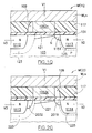
photoresist layer 113 is then completely removed. As shown in FIG. 1L, N type dopants are then implanted. Where thespacers 109 have been removed, such as at the right-hand side of thepolysilicon layer portion 1052, at the left-hand side of thepolysilicon layer portion 1053 and at both sides of thepolysilicon layer portion 1054, the surface of the Ptype semiconductor layer 103 is exposed and the implanted dopants formN type regions N type region polysilicon layer portion regions - Where present, the
N type regions gate electrode drain region N type regions - If desired, after this step the remaining
spacers 109 can be completely removed, or they can be left, as in the shown example. - Then, a relatively thick
dielectric layer 117, such as silicon dioxide, is deposited over the array area. Thedielectric layer 117 is then preferably planarised, for example by means of a chemical-mechanical polishing (CMP), and it is then submitted to an etch process, for example a plasma etch. The thickness of thedielectric layer 117 is progressively reduced until the surface polysilicon layer portions 1051 - 1054 are exposed; portions of thedielectric layer 117 are thus left only in between the polysilicon layer portions 1051 - 1054, flush therewith.. Aconductive layer 119, for example of polysilicon, is then formed on thedielectric layer 117. By conventional photolithographic techniques, thepolysilicon layer 119 is patterned to form word lines of the array, such as the word line WLn shown in FIG. 1M. During the definition of the word lines, also the underlying polysilicon layer portions 1051 - 1054 are selectively etched and removed in between the rows R(n-1), Rn, R(n+1) of the array, thereby forming distinct polysilicon layer segments along each row of the array, such as thepolysilicon layer segments - The N type regions 1111 - 1115 are contacted, outside of the array, by conductive lines, typically in aluminium, routed to a conventional sensing circuitry through a bit line selector (not shown in the drawings).
- The operation of a two-bit ROM cell obtained by means of the manufacturing process described in the foregoing will be now explained.
- Each one of the memory cells MC11 - MC14 stores two bits. Each one of the two bits is stored in a respective one of the two memory cell's bit storage regions comprised between the memory cell's channel region and the source/
drain regions N type regions - In a two-bit ROM cell, the source/drain regions change their roles of source electrode or drain electrode depending on which one of the two bits is to be read.
- Let for example the memory cell MC12 be considered, shown in enlarged view in FIG. 1Q, and let also be assumed that the right-hand bit of this memory cell is to be read. The word line WLn to which the memory cell belong is selected, and the potential thereof raised to a positive voltage V1, e.g. 3 V. This causes the formation of an
inversion layer 121 of the N conductivity type in the region of the Ptype semiconductor layer 103 under thegate electrode 1052n of the memory cell (the memory cell's channel region). In order to read the right-hand bit, the adjacent source/drain region 1113 acts as a source electrode, while the opposite source/drain region 1112 acts as a drain electrode. A ground voltage V2 is applied to the source/drain region 1113, while the opposite source/drain region 1112 is applied a sufficiently high positive voltage V3. The positive voltage V3 applied to the source/drain region 1112 causes adepletion region 123, associated with the PN junction formed by theN type region 1112 and theP type layer 103, to extend laterally to thechannel region 121. Thedepletion region 123 makes the source/drain region 1112 to be electrically connected to theinversion layer 121, irrespective of the absence of a low-resistance N region under the left-hand spacer 109. The ground voltage V2 applied to the source/drain region 1113 causes adepletion region 125, associated with the PN junction formed by theN type region 1113 and theP type layer 103, to have a limited lateral extension and not to reach theinversion layer 121. The electrical connection of the source/drain region 1113 to theinversion layer 121 thus depends on the presence of a low-resistance N type region between theN type region 1113 and the memory cell's channel region. In the case of the memory cell MC12, the presence of the low-resistanceN type region 1151 causes the source/drain region 1113 to be electrically connected to theinversion layer 121; a current thus flows across the memory cell's channel, and the state of the right-hand bit of the memory cell MC12 is thus detected to be a logic "1". - FIGS. 2A to 2F show the main steps of a manufacturing process according to a second embodiment of the present invention. In the drawings, same reference numerals are adopted to identify identical elements in the two embodiments.
- The process steps up to the definition of the polysilicon layer portions 1051 - 1054 are the same as in the first embodiment of the process. Also in this case, the polysilicon layer portions 1051 - 1054 are strips extending orthogonally to the array rows.
- Referring to FIG. 2A, using the polysilicon layer portions 1051 - 1054 as a mask, N type dopants are implanted into the P
type semiconductor layer 103.N type regions - Passing to FIG. 2B, the
sidewall spacers 109 are then formed at the side walls of the polysilicon layer portions 1051 - 1054. - Subsequently, as shown in FIG. 2C, N type dopants are then implanted into the
P type layer 103 to form the N type elongated regions 1111 - 1115 self-aligned with thespacers 109. Portions of the N type regions 2011 - 2015 remain at each side of the N type elongated regions 1111 - 1115, under thespacers 109. - Making reference to FIGS. 2D and 2E, the
programming mask spacers 109 are selectively removed, as in the first embodiment previously described. - As shown in FIG. 2F, the programming mask is then removed, and P type dopants, for example boron ions, are implanted in a dose sufficient to compensate and, preferably, revert the N type doping of the
regions spacer 109. For example, an implant dose ranging from 1012 to 1014 ions/cm2 is suitable.P type regions N type regions regions - The process goes on similarly to the first embodiment previously described, with the optional removal of the remaining spacers, the deposition and etch of the dielectric layer, the deposition and patterning of the word lines and the definition of the memory cells' gate electrodes.
- Each one of the memory cells MC21 - MC24 stores two bits. Each one of the two bits is stored in a respective one of the two memory cell's bit storage regions comprised between the memory cell's channel region and the source/
drain regions N type regions P type regions - Focusing for example on the memory cell MC23, shown in enlarged view in FIG. 2G, and assuming that the right-hand bit of this memory cell is to be read, the word line WLn to which the memory cell belong is selected, and the potential thereof raised to the positive voltage V1. This causes the formation of an
inversion layer 221 of the N conductivity type in the region of the Ptype semiconductor layer 103 under thegate electrode 1053n of the memory cell (the memory cell's channel region). The adjacent source/drain region 1113 acts as a drain electrode, while the opposite source/drain region 1114 acts as a source electrode. The ground voltage V2 is applied to the source/drain region 1114, while the opposite source/drain region 1113 is applied the positive voltage V3. The positive voltage V3 applied to the source/drain region 1112 causes adepletion region 223, associated with the PN junction formed by theN type region 1113 and theP type layer 103, to extend laterally to thechannel region 221. Thedepletion region 223 makes the source/drain region 1113 to be electrically connected to theinversion layer 221, irrespective of the presence of theP type region 2032, which is bypassed. The ground voltage V2 applied to the source/drain region 1114 causes adepletion region 225, associated with the PN junction formed by theN type region 1114 and theP type layer 103, to have a limited lateral extension and not to reach theinversion layer 221. The electrical connection of the source/drain region 1114 to theinversion layer 221 thus depends on the presence of the low-resistanceN type region 2014 between theN type region 1114 and the memory cell's channel region. A current thus flows across the memory cell's channel, and the state of the right-hand bit of the memory cell MC23 is thus detected to be a logic "1". - In the two process embodiments described, the spacer material must be such as to allow a selective removal of the spacers without affecting the polysilicon layer. For example, silicon dioxide and silicon nitride have this characteristic. Another embodiment of the invention will be now described which allow to use any spacer materials, even polysilicon. Such other embodiment will be described, making reference to FIGS. 3A to 3C, as a variant of the first embodiment described, although the technique could as well be applied to the second process embodiment.
- Referring to FIG. 3A, after having defined the polysilicon layer portions 1051 - 1054 as in FIGS. 1C and 1D, a
liner layer 301 is formed over the structure top surface. Theliner layer 301 is for example a layer of silicon nitride. Then, thespacers 109 are formed, as in FIG. 1E. The spacers can be of any suitable material, for example polysilicon. Afterwards, as shown in FIG. 3C, themask 113 is applied and thespacers 109 selectively removed. The presence of theliner layer 301 protects the polysilicon layer portions 1051 - 1054, which are thus not etched even if the etch process, per se, is designed to etch polysilicon. - The process goes on as previously described; during the etch of the
dielectric layer 117, theliner 301 is removed to allow the word lines contacting the gate electrodes of the memory cells. - The use of silicon nitride as a liner layer is not limitative: other materials can be used, provided they allow to protect the polysilicon layer portions during the etches that defines and selectively removes the spacers.
- It can be appreciated that in the process embodiments described in the foregoing, only one program mask is required for selectively removing the spacers where dopants are to be implanted for modifying the resistance of the regions aside the memory cells' channel regions.
- In the process embodiments described, the dopant implants for programming the memory cells are orthogonal to the top surface of the array. This is not to be intended as a limitation of the present invention: the dopants may as well be implanted along tilted directions with respect to the perpendicular to the array top surface; in this case, two implants, instead of a single one, are necessary for programming the memory cells. It is to be observed that the spacers, being flush with the polysilicon layer portions defining the memory cells' gate electrodes, do not shadow the dopant implant in adjacent memory cells. Also in this case, a single programming mask is therefore required, instead of the two programming masks as in the prior art process.
- The use of sidewall spacers as masking elements is advantageous because the conventional process of formation of the spacers allows a relatively good control of the spacer width. A good control of the spacer width is important, since the spacer width determines the separation of the memory cells' source/drain regions from the channel regions. This is an parameter, influencing the voltages to be applied to the source/drain regions of the memory cells, because when a source/drain region acts as a drain of the memory cell, the depletion region associated thereto must extend at least to the edge of the channel region.
- In the previous description, reference has always been made to the formation of an array of memory cells of the contactless type. Albeit the advantages of these structure, this is not to be intended as a limitation of the invention, which can be applied to the fabrication of memory cell arrays of different structure.
- Although the present invention has been disclosed and described by way of some embodiments, it is apparent to those skilled in the art that several modifications to the described embodiments, as well as other embodiments of the present invention are possible without departing from the scope thereof as defined in the appended claims.
Claims (7)
- A process for fabricating a two-bit ROM cell, comprising:characterised in that said providing the differentiated-resistance doped regions comprises:forming a control electrode (1052n,1053n) over a semiconductor layer (103) of a first conductivity type, a region of the semiconductor layer underlying the control electrode constituting a memory cell channel region;providing, on either side of the channel region, differentiated-resistance doped regions (1151-1154:2011-2014,2031-2034) having respective resistance values that depends on a logic state of a respective one of the two bits to be stored in the cell, the resistance values of the differentiated-resistance doped regions being set by means of a selective introduction of dopants,selectively providing sidewall spacers (109) at sidewalls of the control electrode, andusing the sidewall spacers as a mask against the introduction of dopants.
- The process according to claim 1, in which said selectively providing the sidewall spacers comprises forming the sidewall spacers at both the sidewalls of the control electrode, and selectively removing (1131,1132) none, either one or both of the sidewall spacers depending on a respective logic state of the two bits to be stored in the cell.
- The process according to claim 2, further comprising forming in the semiconductor layer a first and a second source/drain regions (1111-1115) of a second conductivity type at the sides of the control electrode, the differentiated-resistance doped regions being interposed between the source/drain regions being and the channel region.
- The process according to claim 3, in which the source/drain regions are formed in self-alignment with the spacers.
- The process according to claim 4, in which the dopants are of the second conductivity type, and the sidewall spacers are removed to form relatively low-resistance doped regions (1151-1154) of the second conductivity type electrically connecting the respective adjacent source/drain region to an inversion channel that forms in the channel region under when the control electrode is biased in prescribed conditions.
- The process according to claim 4, further comprising:before forming the sidewall spacers, forming doped regions (2011-2015) of the second conductivity type at either side of and in self-alignment with the control electrode, andafter having selectively removed the sidewall spacers, introducing dopants of the first conductivity type for increasing a resistivity or reverting a conductivity type of a portion of the doped regions of the second conductivity type interposed between the respective adjacent source/drain region and the channel region.
- The process according to any one of claims 2 to 6, further comprising:before forming the sidewall spacers, forming on the control electrode a protective layer (301).
Priority Applications (1)
| Application Number | Priority Date | Filing Date | Title |
|---|---|---|---|
| EP02425225A EP1353371A1 (en) | 2002-04-12 | 2002-04-12 | Two-bit rom cell manufacturing process |
Applications Claiming Priority (1)
| Application Number | Priority Date | Filing Date | Title |
|---|---|---|---|
| EP02425225A EP1353371A1 (en) | 2002-04-12 | 2002-04-12 | Two-bit rom cell manufacturing process |
Publications (1)
| Publication Number | Publication Date |
|---|---|
| EP1353371A1 true EP1353371A1 (en) | 2003-10-15 |
Family
ID=28051902
Family Applications (1)
| Application Number | Title | Priority Date | Filing Date |
|---|---|---|---|
| EP02425225A Withdrawn EP1353371A1 (en) | 2002-04-12 | 2002-04-12 | Two-bit rom cell manufacturing process |
Country Status (1)
| Country | Link |
|---|---|
| EP (1) | EP1353371A1 (en) |
Citations (5)
| Publication number | Priority date | Publication date | Assignee | Title |
|---|---|---|---|---|
| US4982250A (en) * | 1989-01-04 | 1991-01-01 | Motorola, Inc. | Mosture barrier for floating gate transistors |
| DE19541469A1 (en) * | 1994-11-29 | 1996-05-30 | Mitsubishi Electric Corp | Semiconductor device with mask-programmable memory |
| US5526306A (en) * | 1994-02-10 | 1996-06-11 | Mega Chips Corporation | Semiconductor memory device and method of fabricating the same |
| US5631180A (en) * | 1994-01-07 | 1997-05-20 | Zilog, Inc. | Method of fabricating high threshold metal oxide silicon read-only-memory transistors |
| US5796149A (en) * | 1994-09-09 | 1998-08-18 | Nippon Steel Corporation | Semiconductor memory using different concentration impurity diffused layers |
-
2002
- 2002-04-12 EP EP02425225A patent/EP1353371A1/en not_active Withdrawn
Patent Citations (5)
| Publication number | Priority date | Publication date | Assignee | Title |
|---|---|---|---|---|
| US4982250A (en) * | 1989-01-04 | 1991-01-01 | Motorola, Inc. | Mosture barrier for floating gate transistors |
| US5631180A (en) * | 1994-01-07 | 1997-05-20 | Zilog, Inc. | Method of fabricating high threshold metal oxide silicon read-only-memory transistors |
| US5526306A (en) * | 1994-02-10 | 1996-06-11 | Mega Chips Corporation | Semiconductor memory device and method of fabricating the same |
| US5796149A (en) * | 1994-09-09 | 1998-08-18 | Nippon Steel Corporation | Semiconductor memory using different concentration impurity diffused layers |
| DE19541469A1 (en) * | 1994-11-29 | 1996-05-30 | Mitsubishi Electric Corp | Semiconductor device with mask-programmable memory |
Similar Documents
| Publication | Publication Date | Title |
|---|---|---|
| KR100437470B1 (en) | Semiconductor device having a flash memory cell and fabrication method thereof | |
| US6191459B1 (en) | Electrically programmable memory cell array, using charge carrier traps and insulation trenches | |
| KR100474176B1 (en) | Method for producing a multi-bit memory cell | |
| US7298004B2 (en) | Charge-trapping memory cell and method for production | |
| US7211858B2 (en) | Split gate storage device including a horizontal first gate and a vertical second gate in a trench | |
| US6184093B1 (en) | Method of implementing differential gate oxide thickness for flash EEPROM | |
| US5962900A (en) | High-density diode-based read-only memory device | |
| RU2153210C2 (en) | High-integration semiconductor storage device and its manufacturing process | |
| US6917069B2 (en) | Semiconductor memory array of floating gate memory cells with buried bit-line and vertical word line transistor | |
| KR100251981B1 (en) | Nonvolatile semiconductor memory and method for fabricating the same | |
| KR101025148B1 (en) | A non-volatile floating gate memory cell with floating gates formed in cavities, and array thereof, and method of formation | |
| US6962851B2 (en) | Nonvolatile memories and methods of fabrication | |
| US6359303B1 (en) | Split gate flash memory with virtual ground array structure and method of fabricating the same | |
| US11527630B2 (en) | Semiconductor device and method for fabricating the same | |
| US7016225B2 (en) | Four-bit non-volatile memory transistor and array | |
| US6555870B1 (en) | Nonvolatile semiconductor memory device and method for producing same | |
| US7196372B1 (en) | Flash memory device | |
| JP2001506410A (en) | Memory cell device and method of manufacturing the same | |
| JPH0817948A (en) | Semiconductor device and its manufacture | |
| CN111799270A (en) | Semiconductor device with a plurality of transistors | |
| JP2005524990A (en) | Ultra-small thin window in floating gate transistors defined by lost nitride spacers | |
| US20040238852A1 (en) | Array of integrated circuit units with strapping lines to prevent punch through | |
| KR100308591B1 (en) | Solid-state nonvolatile semiconductor memory device and manufacturing method thereof | |
| US20070026606A1 (en) | Method and structure for fabricating non volatile memory arrays | |
| US6242773B1 (en) | Self-aligning poly 1 ono dielectric for non-volatile memory |
Legal Events
| Date | Code | Title | Description |
|---|---|---|---|
| PUAI | Public reference made under article 153(3) epc to a published international application that has entered the european phase |
Free format text: ORIGINAL CODE: 0009012 |
|
| AK | Designated contracting states |
Kind code of ref document: A1 Designated state(s): AT BE CH CY DE DK ES FI FR GB GR IE IT LI LU MC NL PT SE TR |
|
| AX | Request for extension of the european patent |
Extension state: AL LT LV MK RO SI |
|
| AKX | Designation fees paid | ||
| REG | Reference to a national code |
Ref country code: DE Ref legal event code: 8566 |
|
| STAA | Information on the status of an ep patent application or granted ep patent |
Free format text: STATUS: THE APPLICATION IS DEEMED TO BE WITHDRAWN |
|
| 18D | Application deemed to be withdrawn |
Effective date: 20040416 |