EP1353344A1 - Dispositif pour signaler des informations numériques - Google Patents
Dispositif pour signaler des informations numériques Download PDFInfo
- Publication number
- EP1353344A1 EP1353344A1 EP02100365A EP02100365A EP1353344A1 EP 1353344 A1 EP1353344 A1 EP 1353344A1 EP 02100365 A EP02100365 A EP 02100365A EP 02100365 A EP02100365 A EP 02100365A EP 1353344 A1 EP1353344 A1 EP 1353344A1
- Authority
- EP
- European Patent Office
- Prior art keywords
- signal
- switching device
- switch element
- engine control
- signal voltage
- Prior art date
- Legal status (The legal status is an assumption and is not a legal conclusion. Google has not performed a legal analysis and makes no representation as to the accuracy of the status listed.)
- Granted
Links
- 230000011664 signaling Effects 0.000 title claims description 4
- 238000011156 evaluation Methods 0.000 claims description 7
- 230000007935 neutral effect Effects 0.000 claims description 5
- 230000004913 activation Effects 0.000 claims description 2
- 230000009849 deactivation Effects 0.000 claims description 2
- 238000010292 electrical insulation Methods 0.000 claims description 2
- 238000009413 insulation Methods 0.000 description 4
- 230000008901 benefit Effects 0.000 description 2
- 230000005540 biological transmission Effects 0.000 description 2
- 230000000694 effects Effects 0.000 description 2
- 238000002955 isolation Methods 0.000 description 2
- 238000004519 manufacturing process Methods 0.000 description 2
- 230000009471 action Effects 0.000 description 1
- 230000008878 coupling Effects 0.000 description 1
- 238000010168 coupling process Methods 0.000 description 1
- 238000005859 coupling reaction Methods 0.000 description 1
- 238000001514 detection method Methods 0.000 description 1
- 230000004069 differentiation Effects 0.000 description 1
- 230000036039 immunity Effects 0.000 description 1
- 230000007257 malfunction Effects 0.000 description 1
- 230000007246 mechanism Effects 0.000 description 1
- 238000012544 monitoring process Methods 0.000 description 1
- 230000004044 response Effects 0.000 description 1
- 230000003068 static effect Effects 0.000 description 1
- 230000001052 transient effect Effects 0.000 description 1
- XLYOFNOQVPJJNP-UHFFFAOYSA-N water Substances O XLYOFNOQVPJJNP-UHFFFAOYSA-N 0.000 description 1
Images
Classifications
-
- H—ELECTRICITY
- H01—ELECTRIC ELEMENTS
- H01H—ELECTRIC SWITCHES; RELAYS; SELECTORS; EMERGENCY PROTECTIVE DEVICES
- H01H9/00—Details of switching devices, not covered by groups H01H1/00 - H01H7/00
- H01H9/16—Indicators for switching condition, e.g. "on" or "off"
- H01H9/167—Circuits for remote indication
-
- H—ELECTRICITY
- H01—ELECTRIC ELEMENTS
- H01H—ELECTRIC SWITCHES; RELAYS; SELECTORS; EMERGENCY PROTECTIVE DEVICES
- H01H47/00—Circuit arrangements not adapted to a particular application of the relay and designed to obtain desired operating characteristics or to provide energising current
- H01H47/002—Monitoring or fail-safe circuits
Definitions
- the invention relates to a switching device for secure wired signaling binary information containing a signal voltage connection and a movable switch element connected thereto.
- the invention further relates to an electronic engine control for a motor vehicle, which for the Remote input of binary information is set up.
- Modern motor vehicles have electronic engine control, which Central monitoring and control of a variety of functions in the motor vehicle performs. Activation and are examples of such functions Deactivating a passenger airbag and loosening or pulling it on called an electric handbrake.
- a switching device accessible to the driver, by means of which Actuation of a binary "on / off" information via corresponding connecting lines can be signaled to the engine control.
- Actuation of a binary "on / off" information via corresponding connecting lines can be signaled to the engine control.
- Like the ones mentioned Examples show there are a number of automotive functions with high Safety relevance. Error in the transmission path from that assigned to the driver Switching device for motor control must therefore with high probability are excluded so that the driver's input from the engine control misinterpreted and lead to undesirable effects.
- a binary To transmit information consists of a switch, which depending on the position electrical line to motor control interrupts or closes. If this line at one end with a signal voltage such as a ground potential the motor control input can be connected depending on the switch position be placed on the signal voltage or not, these two states then the two logical values of the binary information to be transmitted represent.
- a switching device is extremely unsafe because a line interruption caused by a fault is not a deliberate one Switch opening can be distinguished. Furthermore, it can, for example, by If water enters the switching device, a short circuit occurs. which would be misinterpreted as closing the switch.
- an object of the present invention was a switching device and an electronic motor control that can be coupled to this To provide a higher level of security when entering a binary Provide information.
- the switching device for the safe wired signaling of a binary "On / Off" information contains a signal voltage connection, which with a Source for a given signal voltage can be connected, as well as a movable switch element electrically connected to the signal voltage connection.
- the switching device is characterized in that these three signal outputs has, of which depending on the position of the switch element one electrically connected to the signal voltage terminal via the switch element is.
- the switching device therefore allows a signal voltage connection supplied signal voltage optionally on exactly one of three signal outputs to lay. This enables a clear interpretation of the switch position at any time, the presence of the signal voltage at a first or second signal output for the two logical values ("true / false") of the binary Information is available and the presence of the signal voltage on third signal output indicate a neutral position of the switch element can, at which no defined value of the binary information is specified.
- This explicitly selectable and evaluable neutral position enables the intended Lack of a choice of a random or fault-related one Lack of differentiation, which is the case, for example, if the Switch element has no contact with any of the signal outputs and / or an interruption the lines are present.
- Another advantage of the switching device is in that a short circuit cannot lead to misconduct. For example, should a short circuit cause another signal output connected to the signal voltage, there would no longer be just one of the three signal outputs at the level of the signal voltage, causing the error would be detectable. Furthermore, the switching device is against a fault protected by a line break, since such a line break lead to a lack of signal voltage on all three signal outputs would, which in turn would represent a recognizable faulty condition.
- the switch element is in one Axis pivotally mounted, and it has a slider, which with contacts connected to the signal outputs.
- the switching device can be turned or pivoted of the switch element of the slider either with one of the contacts in Be brought in contact and thereby the signal voltage applied to the switch element place on the relevant signal output.
- those with the signal outputs are preferred connected contacts by electrical insulation surfaces from each other Cut.
- the slider of the switch element comes thus alternating with contacts and with insulation surfaces in contact, so that ensured with a correspondingly large dimensioning of the insulation surfaces is that the slider never touches two contacts at the same time. This ensures that the signal voltage at a maximum at one time Signal output can be present.
- this is such designed that the switch element only when contacting a signal output is in a mechanically stable position. Between positions in which the switch element the signal voltage with none of the signal outputs connects are therefore mechanically unstable, so that they are within the shortest Leave time alone. This ensures that undefined states, in which the signal voltage is not present at any of the signal outputs, at most be accepted transiently.
- the invention further relates to an electronic engine control for a motor vehicle, which is set up for the remote entry of at least one binary information is.
- the motor controller can in particular be designed as a microcomputer his.
- the engine control is characterized in that these three with an evaluation electronics within the motor control connected signal inputs contains, wherein the evaluation electronics is set up such that it is present a signal voltage at exactly one of the signal inputs as input of the first or the second logical value of the information or as neutral Input interpreted, and that these all other voltage states of the Signal inputs interpreted as errors.
- Such a motor control can provide binary information with great immunity to interference be communicated as the two possible logical values of the information ("true / false", "on / off” etc.) is displayed via a separate signal input become.
- This enables a distinction a deliberate lack of information input from a fault-related Absence, for example due to a line break.
- the engine control system can also detect such accidents where more than accurate a signal voltage is present at a signal input. Such disturbances can for example caused by short circuits. They are used by the evaluation electronics recognized, so that malfunction of the engine control can be prevented can.
- the motor control described above can in particular with a Switching device of the type explained above can be coupled, since this Switching device the assignment suitable for the evaluation behavior of the motor control which has signal outputs.
- this is set up that this the lack of signal voltage at all three signal inputs only interpreted as an error if this absence is longer than a specified one Duration persists.
- Such a waiting period takes into account that when the In terms of circuitry, signal assignment often results in undefined intermediate states can occur, for example, at no signal input or at multiple signal inputs can have a signal voltage applied at the same time.
- the binary information transmitted to the motor controller by remote input can especially the command to open or close an electrical one Signal handbrake or the deactivation of an airbag.
- safety-critical functions in which a faulty Information transmission with the highest possible probability excluded should be. The latter is possible with the motor control according to the invention.
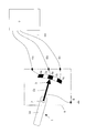
- the switching device 9 shown in the figure meets these requirements.
- the switching device consists of a pivotable about an axis 2 Switch element 1, which has an insulated handle 1a which can be actuated by the driver has an electrically conductive section 1 b.
- a slider 3 is arranged, which along a circular arc Contact distance can slide when the switch element 1 around Axis 2 is pivoted.
- the conductive section 1b is also via a line connected to a signal voltage input 8, which in the connected state the switching device 9 is connected to the ground potential.
- first contact 4a Along the curved path of movement of the slider 3 are alternating Order of a first contact 4a, a first insulation area 5a, a second contact 4b, a second insulation area 5b and a third contact 4c are arranged.
- the three contacts 4a-c mentioned are with corresponding signal outputs 6a-c the switching device 9 connected. These signal outputs are connected State one to one with corresponding signal inputs on a motor control 7 connected.
- the motor controller 7 which is designed as a microcomputer, contains evaluation electronics (not shown) which interpret the conditions prevailing at the three signal inputs 6a-c as follows (a "1" stands for a state in which the signal voltage is present at the relevant signal input): Signal input 6a Signal input 6b Signal input 6c Coded information: 0 1 0 Neutral position (no action) 1 0 0 Run / Close / Down 0 0 1 Releasing / opening / top All other combinations invalid
- a spring mechanism is preferably used in the switching device 9 provided by which the residence time of the glider 3 on the Isolation areas 5a, 5b is kept below a certain maximum value, which does not allow the driver to switch element 1 for a longer period of time to put in an intermediate position.
- the motor controller 7 can in a simple manner between a brief, transient interruption during normal switch operation and a permanent error (e.g. line break).
- a typical application of the system described is remote entry a "release / apply" command for an electric handbrake.
Priority Applications (3)
| Application Number | Priority Date | Filing Date | Title |
|---|---|---|---|
| EP02100365A EP1353344B1 (fr) | 2002-04-11 | 2002-04-11 | Dispositif pour signaler des informations numériques |
| DE50207634T DE50207634D1 (de) | 2002-04-11 | 2002-04-11 | Schaltvorrichtung zur Signalisierung einer binaeren information |
| US10/249,467 US20030193766A1 (en) | 2002-04-11 | 2003-04-11 | Switching Device For Signaling A Binary Information Item |
Applications Claiming Priority (1)
| Application Number | Priority Date | Filing Date | Title |
|---|---|---|---|
| EP02100365A EP1353344B1 (fr) | 2002-04-11 | 2002-04-11 | Dispositif pour signaler des informations numériques |
Publications (2)
| Publication Number | Publication Date |
|---|---|
| EP1353344A1 true EP1353344A1 (fr) | 2003-10-15 |
| EP1353344B1 EP1353344B1 (fr) | 2006-07-26 |
Family
ID=28051829
Family Applications (1)
| Application Number | Title | Priority Date | Filing Date |
|---|---|---|---|
| EP02100365A Expired - Fee Related EP1353344B1 (fr) | 2002-04-11 | 2002-04-11 | Dispositif pour signaler des informations numériques |
Country Status (3)
| Country | Link |
|---|---|
| US (1) | US20030193766A1 (fr) |
| EP (1) | EP1353344B1 (fr) |
| DE (1) | DE50207634D1 (fr) |
Families Citing this family (4)
| Publication number | Priority date | Publication date | Assignee | Title |
|---|---|---|---|---|
| US20040123027A1 (en) * | 2002-10-03 | 2004-06-24 | Workman Michael Lee | Systems and methods of multiple access paths to single ported storage devices |
| US9387861B1 (en) | 2010-12-03 | 2016-07-12 | Pedal Logic Lp | System, method, and apparatus for optimizing acceleration in a vehicle |
| US9481375B2 (en) * | 2010-12-03 | 2016-11-01 | Pedal Logic Lp | Method and apparatus to adjust for undesired force influencing a vehicle input control |
| US10023138B1 (en) | 2017-01-17 | 2018-07-17 | Pedal Logic Lp | Power connection for a vehicular acceleration input control apparatus |
Citations (1)
| Publication number | Priority date | Publication date | Assignee | Title |
|---|---|---|---|---|
| EP0818645A1 (fr) * | 1996-07-08 | 1998-01-14 | Ford Global Technologies, Inc. | Capteur de position pour levier de commande de boíte de vitesses |
Family Cites Families (4)
| Publication number | Priority date | Publication date | Assignee | Title |
|---|---|---|---|---|
| US4249045A (en) * | 1979-02-26 | 1981-02-03 | Spaderna Conan H | Selector switch |
| US5053960A (en) * | 1987-05-29 | 1991-10-01 | J. I. Case Company | Electronic control system for powershift transmission with compensation for variation in supply voltage |
| US4859987A (en) * | 1987-12-11 | 1989-08-22 | Casco Products Corporation | Apparatus and method for monitoring liquid levels |
| US5191971A (en) * | 1991-04-05 | 1993-03-09 | Lutron Electronics Co., Inc. | Multi-position wall mountable control switch with tactile feedback linear actuator |
-
2002
- 2002-04-11 DE DE50207634T patent/DE50207634D1/de not_active Expired - Lifetime
- 2002-04-11 EP EP02100365A patent/EP1353344B1/fr not_active Expired - Fee Related
-
2003
- 2003-04-11 US US10/249,467 patent/US20030193766A1/en not_active Abandoned
Patent Citations (1)
| Publication number | Priority date | Publication date | Assignee | Title |
|---|---|---|---|---|
| EP0818645A1 (fr) * | 1996-07-08 | 1998-01-14 | Ford Global Technologies, Inc. | Capteur de position pour levier de commande de boíte de vitesses |
Also Published As
| Publication number | Publication date |
|---|---|
| EP1353344B1 (fr) | 2006-07-26 |
| US20030193766A1 (en) | 2003-10-16 |
| DE50207634D1 (de) | 2006-09-07 |
Similar Documents
| Publication | Publication Date | Title |
|---|---|---|
| EP2586051B1 (fr) | Montage de sécurité permettant de mettre sous ou hors tension une installation dangereuse en toute sécurité | |
| EP3271932B1 (fr) | Commutateur de sécurité pour interrompre une charge électrique sans erreur | |
| EP1200846A1 (fr) | Ensemble actionneur, servant notamment a commander une soupape d'injection d'un moteur a combustion interne | |
| EP1363306B1 (fr) | Interrupteur de sécurité, circuit de sécurité et procédé de commande d'un interrupteur de sécurité | |
| EP1873915B1 (fr) | Circuit d'entrée sécurisé doté d'un raccordement périphérique sur un canal unique pour l'entrée d'un utilisateur de bus | |
| WO2006128504A1 (fr) | Systeme de multiplexage pour reguler des charges dans des bateaux ou des caravanes | |
| EP0269648B1 (fr) | Circuit pour au moins un comsommateur electrique d'un vehicule a moteur | |
| DE102006027135B3 (de) | Verfahren zum Betrieb einer Vorrichtung, insbesondere eines Sicherheitsschalters, und die Vorrichtung | |
| DE102006009729A1 (de) | Verfahren und Vorrichtung zum Steuern eines elektrisch betä-tigbaren Verbrauchers in einem Fahrzeug, insbesondere einer Feststellbremse | |
| DE19909968A1 (de) | Sicherheitsschalteinrichtung für elektrisch gesteuerte Maschinen | |
| EP0149727B1 (fr) | Circuit de surveillance pour les contacts de sécurité d'ascenceurs | |
| WO2005047759A2 (fr) | Dispositif et procede pour realiser la commutation sans erreur d'un recepteur inductif | |
| EP1364459B1 (fr) | Dispositif de commutation de securite | |
| EP1353344A1 (fr) | Dispositif pour signaler des informations numériques | |
| DE4409541A1 (de) | Sicherheitstechnische Einrichtung | |
| EP0532787B1 (fr) | Dispositif pour l'opération de détecteurs de dangers | |
| DE10393280B4 (de) | Getriebevorrichtung und Verfahren zum Betreiben einer Getriebevorrichtung | |
| EP0809361A2 (fr) | Dispositif électronique de commutation et circuit pour la surveillance d'une installation technique | |
| EP1170849B1 (fr) | Procédé de commande et circuit correspondant | |
| EP0809266A2 (fr) | Appareil de commutation à basse tension | |
| EP0660044B1 (fr) | Dispositif de commande pour commander des appareils de commutation | |
| EP1447830B1 (fr) | Dispositif de commutation pour le codage de différents états | |
| DE102014017906A1 (de) | Lenkrad mit Wechselschalter | |
| DE10148155A1 (de) | Anordnung zur Überwachung von Motorstartern | |
| DE102015215847B3 (de) | Vorrichtung und Verfahren zur Erhöhung der funktionalen Sicherheit in einem Fahrzeug. |
Legal Events
| Date | Code | Title | Description |
|---|---|---|---|
| PUAI | Public reference made under article 153(3) epc to a published international application that has entered the european phase |
Free format text: ORIGINAL CODE: 0009012 |
|
| AK | Designated contracting states |
Kind code of ref document: A1 Designated state(s): AT BE CH CY DE DK ES FI FR GB GR IE IT LI LU MC NL PT SE TR |
|
| AX | Request for extension of the european patent |
Extension state: AL LT LV MK RO SI |
|
| 17P | Request for examination filed |
Effective date: 20040415 |
|
| AKX | Designation fees paid |
Designated state(s): DE FR GB |
|
| GRAP | Despatch of communication of intention to grant a patent |
Free format text: ORIGINAL CODE: EPIDOSNIGR1 |
|
| RAP1 | Party data changed (applicant data changed or rights of an application transferred) |
Owner name: FORD GLOBAL TECHNOLOGIES, LLC |
|
| RAP1 | Party data changed (applicant data changed or rights of an application transferred) |
Owner name: FORD GLOBAL TECHNOLOGIES, LLC. |
|
| GRAS | Grant fee paid |
Free format text: ORIGINAL CODE: EPIDOSNIGR3 |
|
| GRAA | (expected) grant |
Free format text: ORIGINAL CODE: 0009210 |
|
| AK | Designated contracting states |
Kind code of ref document: B1 Designated state(s): DE FR GB |
|
| REG | Reference to a national code |
Ref country code: GB Ref legal event code: FG4D Free format text: NOT ENGLISH |
|
| REF | Corresponds to: |
Ref document number: 50207634 Country of ref document: DE Date of ref document: 20060907 Kind code of ref document: P |
|
| GBT | Gb: translation of ep patent filed (gb section 77(6)(a)/1977) |
Effective date: 20061101 |
|
| ET | Fr: translation filed | ||
| PLBE | No opposition filed within time limit |
Free format text: ORIGINAL CODE: 0009261 |
|
| STAA | Information on the status of an ep patent application or granted ep patent |
Free format text: STATUS: NO OPPOSITION FILED WITHIN TIME LIMIT |
|
| 26N | No opposition filed |
Effective date: 20070427 |
|
| REG | Reference to a national code |
Ref country code: FR Ref legal event code: PLFP Year of fee payment: 14 |
|
| PGFP | Annual fee paid to national office [announced via postgrant information from national office to epo] |
Ref country code: GB Payment date: 20150325 Year of fee payment: 14 |
|
| PGFP | Annual fee paid to national office [announced via postgrant information from national office to epo] |
Ref country code: DE Payment date: 20150429 Year of fee payment: 14 |
|
| PGFP | Annual fee paid to national office [announced via postgrant information from national office to epo] |
Ref country code: FR Payment date: 20150325 Year of fee payment: 14 |
|
| REG | Reference to a national code |
Ref country code: DE Ref legal event code: R119 Ref document number: 50207634 Country of ref document: DE |
|
| GBPC | Gb: european patent ceased through non-payment of renewal fee |
Effective date: 20160411 |
|
| REG | Reference to a national code |
Ref country code: FR Ref legal event code: ST Effective date: 20161230 |
|
| PG25 | Lapsed in a contracting state [announced via postgrant information from national office to epo] |
Ref country code: DE Free format text: LAPSE BECAUSE OF NON-PAYMENT OF DUE FEES Effective date: 20161101 Ref country code: GB Free format text: LAPSE BECAUSE OF NON-PAYMENT OF DUE FEES Effective date: 20160411 Ref country code: FR Free format text: LAPSE BECAUSE OF NON-PAYMENT OF DUE FEES Effective date: 20160502 |