EP1353246A2 - Safety switch arrangement - Google Patents
Safety switch arrangement Download PDFInfo
- Publication number
- EP1353246A2 EP1353246A2 EP03005564A EP03005564A EP1353246A2 EP 1353246 A2 EP1353246 A2 EP 1353246A2 EP 03005564 A EP03005564 A EP 03005564A EP 03005564 A EP03005564 A EP 03005564A EP 1353246 A2 EP1353246 A2 EP 1353246A2
- Authority
- EP
- European Patent Office
- Prior art keywords
- arrangement according
- safety
- switch arrangement
- safety switch
- monitor
- Prior art date
- Legal status (The legal status is an assumption and is not a legal conclusion. Google has not performed a legal analysis and makes no representation as to the accuracy of the status listed.)
- Granted
Links
Images


Classifications
-
- G—PHYSICS
- G05—CONTROLLING; REGULATING
- G05B—CONTROL OR REGULATING SYSTEMS IN GENERAL; FUNCTIONAL ELEMENTS OF SUCH SYSTEMS; MONITORING OR TESTING ARRANGEMENTS FOR SUCH SYSTEMS OR ELEMENTS
- G05B19/00—Programme-control systems
- G05B19/02—Programme-control systems electric
- G05B19/04—Programme control other than numerical control, i.e. in sequence controllers or logic controllers
- G05B19/042—Programme control other than numerical control, i.e. in sequence controllers or logic controllers using digital processors
-
- G—PHYSICS
- G05—CONTROLLING; REGULATING
- G05B—CONTROL OR REGULATING SYSTEMS IN GENERAL; FUNCTIONAL ELEMENTS OF SUCH SYSTEMS; MONITORING OR TESTING ARRANGEMENTS FOR SUCH SYSTEMS OR ELEMENTS
- G05B9/00—Safety arrangements
- G05B9/02—Safety arrangements electric
-
- G—PHYSICS
- G05—CONTROLLING; REGULATING
- G05B—CONTROL OR REGULATING SYSTEMS IN GENERAL; FUNCTIONAL ELEMENTS OF SUCH SYSTEMS; MONITORING OR TESTING ARRANGEMENTS FOR SUCH SYSTEMS OR ELEMENTS
- G05B2219/00—Program-control systems
- G05B2219/20—Pc systems
- G05B2219/24—Pc safety
- G05B2219/24003—Emergency stop
-
- G—PHYSICS
- G05—CONTROLLING; REGULATING
- G05B—CONTROL OR REGULATING SYSTEMS IN GENERAL; FUNCTIONAL ELEMENTS OF SUCH SYSTEMS; MONITORING OR TESTING ARRANGEMENTS FOR SUCH SYSTEMS OR ELEMENTS
- G05B2219/00—Program-control systems
- G05B2219/20—Pc systems
- G05B2219/24—Pc safety
- G05B2219/24021—Separate processor for monitoring system
-
- G—PHYSICS
- G05—CONTROLLING; REGULATING
- G05B—CONTROL OR REGULATING SYSTEMS IN GENERAL; FUNCTIONAL ELEMENTS OF SUCH SYSTEMS; MONITORING OR TESTING ARRANGEMENTS FOR SUCH SYSTEMS OR ELEMENTS
- G05B2219/00—Program-control systems
- G05B2219/20—Pc systems
- G05B2219/24—Pc safety
- G05B2219/24189—Redundant processors monitor same point, common parameters
-
- G—PHYSICS
- G05—CONTROLLING; REGULATING
- G05B—CONTROL OR REGULATING SYSTEMS IN GENERAL; FUNCTIONAL ELEMENTS OF SUCH SYSTEMS; MONITORING OR TESTING ARRANGEMENTS FOR SUCH SYSTEMS OR ELEMENTS
- G05B2219/00—Program-control systems
- G05B2219/30—Nc systems
- G05B2219/50—Machine tool, machine tool null till machine tool work handling
- G05B2219/50198—Emergency stop
-
- H—ELECTRICITY
- H04—ELECTRIC COMMUNICATION TECHNIQUE
- H04L—TRANSMISSION OF DIGITAL INFORMATION, e.g. TELEGRAPHIC COMMUNICATION
- H04L12/00—Data switching networks
- H04L12/28—Data switching networks characterised by path configuration, e.g. LAN [Local Area Networks] or WAN [Wide Area Networks]
- H04L12/40—Bus networks
- H04L2012/40208—Bus networks characterized by the use of a particular bus standard
- H04L2012/40254—Actuator Sensor Interface ASI
Definitions
- the invention relates to a safety switch arrangement according to the preamble of claim 1.
- Such safety switch arrangements are particularly safe Switching on and off of work equipment used in safety-critical Applications are used. Examples of such tools are presses, folding machines and the like. With such tools danger areas are monitored by means of sensors and the like in order to Exclude hazards to operators. A release of an implement takes place via the respective safety switch arrangement only if there is no object or person in the respective danger zone.
- a large number of sensors are typically used in complex systems and actuators for the operation and monitoring of such tools.
- DE 198 15 147 A1 relates to an arrangement of sensors for monitoring of an implement, which depending on the switching states of the Sensors can be put into operation, the sensors being slaves one after the other Form bus-master system working from a master Master forming control unit is controlled. There is a redundant one on the bus system Evaluation unit connected, which is continuously the over the bus system listens to the transmitted signals. In the evaluation unit, the signals of the sensors, which have an individual coding, their Switching states determined. Only if the coding is correctly identified the implement is put into operation via the evaluation unit.
- the redundant evaluation unit of this arrangement forms a safety monitor.
- This safety monitor determines centrally from the coding of the Control signals the switching states of the sensors, then depending these switching states the activation or deactivation of an implement is controlled centrally.
- the object of the invention is based on an expanded safety concept for the safety switch arrangement mentioned at the beginning provide.
- the safety switch arrangement according to the invention has a predefined one Number of output stages generating switching signals, depending on of the switching signals to the equipment connected to the output stages can be activated or deactivated.
- the output stages form slaves of a bus system operating according to the master-slave principle, which at least a safety monitor for listening to those transmitted via the bus system Signals is assigned.
- the security monitor are during Components of the bus system can be configured during a configuration phase and / or connectable.
- the basic idea of the invention is therefore that the or each safety monitor not only during the operation of the bus system, but also during the configuration phase to configure the bus system or Components of which are the essential safety functions for compliance a given security category.
- the safety monitor expediently indicates compliance with the required Security category based on a redundant structure.
- the master is involved in the implementation of the Configuration only to provide the control functions of the bus system needed while performing the security-related functions configuration by the safety monitor alone become.
- the master is during configuration even deactivated. Then the master functions taken over by the or a safety monitor.
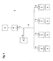
- FIG. 1 schematically shows the structure of a safety switch arrangement 1.
- the safety switch arrangement 1 essentially consists of a The sensor-actuator bus system works according to the master-slave principle and is used for Activation and deactivation of a number of implements 2, 2 '.
- the tools 2, 2 'in the present case consist of an arrangement of Motors with which a safety-relevant process is controlled.
- the motors are each controlled by an output stage 3.
- the case is the output stages 3, 3 'each of one actuator, in particular one or more relays.
- the bus system will centrally controlled by a master 4, which in turn is connected to a controller, in particular a PLC controller 5 is connected.
- Master 4 is from a control circuit is formed.
- the master 4 and the slaves are via bus lines 6 connected to each other.
- the power supply of the sensor-actuator bus system thus formed takes place via a power supply unit, not shown.
- Master 4 cyclically polls the individual slaves at specified addresses from which each slave sends a response to master 4.
- the bus system is formed by the ASi bus system.
- the ASi bus system is especially for the connection of binary sensors and Actuators designed.
- the functioning of the ASi bus system is in "ASI - Das Actuator Sensor Interface for Automation”, Werner Kriesel, Otto W. Madelung, Carl Hanser Verlag, 1994, whose content in the disclosure content this registration is involved.
- a master request (master request MR) consists of one Start bit, a 5-bit address, 2-bit control information, 4-bit user data as well as one parity and one stop bit.
- the associated slave response (slave response SR) contains a start bit, 4 bit user data and one each Parity and stop bit.
- a slave checks the received master call based on specified ASi-specific coding rules. Detects the slave a valid master call, it sends a corresponding answer. In all he does not answer other cases. Master 4 also rejects a slave response, if it does not comply with the relevant coding rules.
- the data are Manchester-coded and are transmitted as alternating, sin 2 -shaped voltage pulses via the bus lines 6.
- the master 4 is assigned an analog circuit 7, which has a transmission element (not shown) and a reception element.
- the binary data of a master call are converted into a sequence of sin 2 -shaped voltage pulses in the transmission element. These signals are sent to the slaves via the bus lines 6.
- the signals sent from the slaves via the bus lines 6 to the master 4 are converted into binary data sequences in the receiving element.
- Each slave has an interface module 8, which in the present example is formed by an Asi-IC.
- the sequences of sin 2 -shaped voltage pulses received via the bus line 6 are converted into binary data.
- the slave response which is in the form of binary data, is sent to the master 4 in a sequence of sin 2 -shaped voltage pulses and via the bus lines 6.
- the security monitor 9 represents a purely passive bus subscriber, which continuously listens to the signals transmitted on the bus lines 6.
- the safety monitor has 9 an interface module 8, whereby this as a slave Can output signals on the bus system.
- the master 4 takes over only that Control of the functions of the bus system. All security-relevant In contrast, functions are taken over by the safety monitor 9.
- the Master 4 has a single-channel structure.
- the output stages 3, 3 'as slaves of the bus system are used for activation and deactivating the work tools 2, 2 '.
- the output stages 3 thus fulfill 3 'security-relevant functions and typically have a redundant Building on.
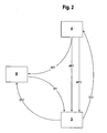
- FIG 2 is the diagram of the data transmission of the individual components the safety switch arrangement 1 shown in Figure 1, with the clarity only one of the output stages 3, 3 'is shown.
- the codes are stored as setpoints, encode the different switching signals for the downstream implement 2.
- the codes consist of a sequence of eight Digits.
- the codes are structured such that a first code is a primary sequence of eight digits.
- the remaining codes form secondary sequences, which are followed by Variations in the order of the digits of the primary sequence are derived from this are.
- the codes each comprise eight digits.
- everyone between a call transmitted to a master 4 and a slave via the bus lines 6 In addition to the address, it has a user data field of 4 bits in which the code is transmitted. Therefore, the eight-digit code must be in individual data strings divided by 4 bits and successively in several calls via the bus system be sent.
- the SR2 call consists of several individual calls. For the sake of clarity, the following is one such a series of calls as the SR2 call is shortened as a single call shown.
- the output stage 3 is driven according to the diagram shown in FIG. 2.
- the master 4 sends a first master request call to the safety monitor 9 MR1. Since the security-relevant information-forming codes in the Safety monitor 9 are stored, this call MR1 does not yet contain any Code for output stages 3, 3 '.
- the MR1 call is made by the safety monitor 9 answered.
- the response SR1 contains a code for Control of the output stage 3.
- the MR1 call and the SR1 response overheard from output stage 3, bringing the code into the output stage 3 is read.
- the code read in via response SR1 is included in output stage 3 the stored setpoint codes compared. If the read codes with one of the stored codes is a positive one Control result generated. Otherwise a negative control result is generated.
- the master request MR1 is now followed by a second master request MR2 to the output stage 3.
- the response SR2 contains this Control result, the answer to the safety monitor 9 being listened to.
- the safety monitor 9 continuously checks the control results of the slaves. If the safety monitor 9 makes a deviation at least of a control result from a predetermined target behavior, the Security monitor 9 predefined measures.
- the activation of the safety monitor 9 is not yet possible deactivated work tools 2 are maintained until, for example, over the master 4 or a controller connected to it the work equipment 2, braked in a controlled manner or brought into a rest position.
- feedback SR2 can be used to call SR1 read code cyclically monitors the functionality of output stages 3 become.
- the switching signals entered in this way to the output stages 3, 3 ' are safety-relevant signals that are used by the motor in the Normal operation or in reduced operation switched on or off becomes. Signals that are not safety-relevant, such as the specification of the exact ones Motor speed is carried out via the PLC control 5 of the bus system 1 and can expediently transmit with the MR2 calls become. This results in the output signal of an output stage 3 as Combination of a release signal generated in the safety monitor 9, which is formed by the switching signal, and one the operation of the implement 2nd controlling control signal from the PLC controller 5.
- FIG. 3 shows a modification of the arrangement according to FIG. 2.
- Such an input / output stage 10 can be, for example, from a light grid be educated.
- the light grid has several light barriers, their light beams Form beam axes.
- the beam axes define one in one plane lying monitoring area within which objects can be detected.
- a light grid can create a danger zone on a working device 2, For example, a press brake can be monitored.
- a corresponding one Object detection signal generated in the light grid. This forms the output signal which is used to generate the switching signal for the implement 2.
- the implement 2 is only activated when there is no object in the Monitoring area is located. Otherwise, the implement 2 is deactivated.
- Blanking zones are entered into the light grid, with which they are not The beam axes of the light grid that cover safety-critical areas are hidden so that when an object intrudes into a blanking zone, no corresponding object detection signal is generated.
- a working device 2 can be operated directly via the input / output stage 10 or via the security monitor 9, which may be a controls additional output stage 3 or an input / output stage 10, activated and be deactivated.
- the input / output stage 10 can be of one Surface distance sensor can be formed, by means of which objects are located in one plane can be. Various parameters are in the area distance sensor Protective fields saved. The area distance sensor is application-specific a certain protective field is selected. Then with that Area distance sensor detects whether an object is in the protective field or Not.
- the implement 2 is only activated when if there is no object in the protective field. Otherwise, the implement 2 deactivated.
- Figure 3 is the diagram of data transmission between the master 4, the Safety monitor 9 and the slave designed as input / output stage 10 shown.
- the switching signals of the input / output stage 10 for activation or deactivation of the implement 2 predetermined. can continue in this way the input / output stage 10 by specifying more specific Blanking zones or specific protective field settings can be specified.
- the configuration 3 over the call SR2 input code input signals from the Input / output stage 10 read. This includes the currently determined object detection signals and the current status of the blanking zone set or the currently set protective field.
- an input / output stage 10 can in the safety monitor 9 output signals are generated to act as parameters for example the blanking zones or protective fields of other input / output stages 10 to change in a predetermined manner.
- FIG. 4 shows the safety switch arrangement 1 with a circuit by means of which the bus system can be configured for before it is commissioned. This is to the safety monitor 9, an operating unit 11 connected by a Computer unit, in particular is formed by a personal computer. Otherwise the circuit arrangement according to FIG. 4 is identical to the arrangement according to FIG. 1.
- a configuration phase is initialized by means of the control unit 11, within which configures the bus system or at least components thereof become.
- the configuration is carried out completely by the safety monitor 9 controlled and controlled, whereby input data for the implementation of the configuration entered into the safety monitor 9 via the control unit 11 become.
- the configuration is carried out such that during In the configuration phase, master 4 of the bus system remains activated.
- the Master 4 then asks the bus participants, namely the connected slaves and the safety monitor 9 among those assigned to these components Addresses cyclically. It is essential here that the master 4 only these master functions takes over, all security-relevant functions for configuration of the bus system, however, are taken over by the safety monitor 9.
- the device-specific parameters in particular are the respective device type of a slave defining codes that are stored in the relevant slaves are transmitted from the respective slave to the safety monitor 9.
- the individual slaves are used as device-specific parameters Device versions in the form of codes in the safety monitor 9 read.
- a slave is preferably not only the current slave Device version, but also the previous device versions. To the current version status with the History of previous versions read into the safety monitor 9.
- the safety monitor 9 controls on the basis of that of the slaves read device versions, which of these device versions with each other are compatible. Depending on this check, the safety monitor sets 9 determines under which device version the individual slaves each during of the operation of the bus system for a specific application become. For example, if there is a new device version for a slave, the not yet available for the remaining slaves and not compatible with the device versions of these remaining slaves, it is agreed in the safety monitor 9 that that the one slave is not called under its current device version shall be. Rather, it is agreed that the slave is in operation the bus system is to be addressed under an earlier device version, which is compatible with the device versions of the remaining slaves.
- Another example of the configuration of slaves is that It can be specified via the safety monitor 9 whether a restart interlock in a slave is activated or deactivated.
- the geometric data of the blanking zones can be used can be specified as optical parameters.
- such protective fields which are typically defined during a teach-in process according to predefined rules and stored in the respective area distance sensor, even during a configuration phase as device parameters in the safety monitor 9 read in and stored there. Will be during another Configuration phase of the relevant area distance sensors against a new one Device replaced, so the protective field stored in the safety monitor 9 can be read directly into the new device.
- the configuration phase is preferably carried out via an input command on the Control unit 11 ends, whereupon the operation of the bus system is started.
- the master 4 becomes during the configuration phase disabled.
- the master functions from the Security monitor 9 adopted.
- Master 4 is used to deactivate disconnected from the bus system or by means of a control command into an off line Operation set.
- the security monitor 9 registers the deactivation of the Masters 4 and then takes over the master functions automatically. As soon as the master 4 is reactivated, it takes over from the safety monitor 9 the master functions again.
- the bus system is configured in the same way as the configuration with activated master 4.
- the configuration phase can also take place during the operation of the bus system can be initiated by, for example, a Exchange slave.
- the configuration phase is initialized a switch, not shown, or the like on the safety monitor 9 operated.
- the new slave is added during the configuration phase assigned an address.
- the slave then becomes analogous to the previous ones Embodiments configured.
- FIG. 5 shows the functioning of a second embodiment of the safety switch arrangement 1 according to the invention.
- the safety switch arrangement 1 is in turn formed by a master-slave bus system which is controlled by a master 4.
- a PLC controller 5 is in turn connected to the master 4.
- two redundant safety monitors 9 are provided, the address A 1 being assigned to the first safety monitor 9 and the address A 2 being assigned to the second safety monitor 9.
- a safety monitor 9 with two addresses A 1 , A 2 can also be used.
- output stages 3, 3 'are provided as slaves, which are analog to the embodiment of Figure 1 are formed by relays that operate control of tools 2, 2 'forming motors.
- the motors are used, for example for driving components of a conveyor line.
- the input stages 12, 12 ' are in the present case designed as an emergency stop switch.
- the input stages 12, 12 ' formed by sensors.
- the output stages 3, 3 'and the subordinate tools 2, 2' are in divided into two groups.
- the safety switch arrangement 1 operates according to the figure 5 as follows:
- the first group of output stages 3 and implements 2 is driven via SR1 views shown in FIGS 2 and 3 at the address A 1 of the first safety monitor 9, ie, the output stage 3, only hear the emitted at the address A 1 Views SR1 of the first safety monitor 9 with, the control results of output stages 3 being reported back via SR2 calls.
- the second group of output stages 3 'and implements 2' is controlled via SR1 calls according to FIGS. 2 and 3 at address A 2 of the second security monitor 9, ie the output stages 3 'only hear the calls SR1 of the second one sent under address A 2 Security monitor 9 with, the control results of the output stages 3 'are reported back via SR2 calls.
- the control of the first group of output stages 3 is dependent the input signals generated by the first input stage 12.
- the operation of the work tools 2 is released via the output stages 3 only if the emergency stop switch forming the input stage 12 is not actuated.
- the second group of output stages 3 'in is likewise activated Dependence of the input signals generated by the second input stage 12 '.
- the operation of the working devices 2 ' is released via the Output stages 3 'only if the emergency stop switch forming the input stage 12' is not actuated.
- the safety switch arrangement 1 is operated according to the figure 4 analogous to the embodiment according to FIG. 1.
- a personal computer is connected as an operating unit to one of the security monitors 9, in the present case to the second security monitor 9 with the address A 2, as shown in FIG.
- the master 4 disabled.
- the safety monitor takes over 9, to which the control unit 11 is connected, the Master roles.
- the configuration can be carried out in such a way that each safety monitor 9 regardless of the other security monitor 9 that him assigned subsystem configured.
- This variant is particularly independent working subsystems make sense.
- the Configuration of the entire system by a safety monitor 9 alone be performed.
- the same security monitor 9 advantageously takes over Configuration, which also took over the master functions.
- each security monitor 9 is stored in each security monitor 9 as basic information, which one Security monitor 9 with a multiple arrangement of security monitors 9 should configure the bus system.
Abstract
Description
Die Erfindung betrifft eine Sicherheitsschalteranordnung gemäß dem Oberbegriff des Anspruchs 1.The invention relates to a safety switch arrangement according to the preamble of
Derartige Sicherheitsschalteranordnungen werden insbesondere zum sicheren Ein- und Ausschalten von Arbeitsgeräten eingesetzt, die in sicherheitskritischen Applikationen eingesetzt werden. Beispiele für derartige Arbeitsgeräte sind Pressen, Abkantmaschinen und dergleichen. Bei derartigen Arbeitsgeräten werden Gefahrenbereiche mittels Sensoren und dergleichen überwacht, um Gefährdungen von Bedienpersonen auszuschließen. Eine Freigabe eines Arbeitsgerätes erfolgt über die jeweilige Sicherheitsschalteranordnung nur dann, wenn sich kein Objekt bzw. keine Person im jeweiligen Gefahrenbereich befindet.Such safety switch arrangements are particularly safe Switching on and off of work equipment used in safety-critical Applications are used. Examples of such tools are presses, folding machines and the like. With such tools danger areas are monitored by means of sensors and the like in order to Exclude hazards to operators. A release of an implement takes place via the respective safety switch arrangement only if there is no object or person in the respective danger zone.
Bei komplexen Anlagen werden typischerweise eine Vielzahl von Sensoren und Aktoren zum Betrieb und zur Überwachung derartiger Arbeitsgeräte benötigt.A large number of sensors are typically used in complex systems and actuators for the operation and monitoring of such tools.
Die DE 198 15 147 A1 betrifft eine Anordnung von Sensoren zur Überwachung eines Arbeitsgerätes, welches in Abhängigkeit der Schaltzustände der Sensoren in Betrieb setzbar ist, wobei die Sensoren Slaves eines nach dem Master-Slave-Prinzip arbeitenden Bussystems bilden, welches von einer den Master bildenden Steuereinheit gesteuert ist. An das Bussystem ist eine redundante Auswerteeinheit angeschlossen, welche fortlaufend die über das Bussystem übertragenen Signale abhört. In der Auswerteeinheit werden aus den Signalen der Sensoren, welchen eine individuelle Kodierung aufgeprägt ist, deren Schaltzustände ermittelt. Nur bei fehlerfreier Identifizierung der Kodierung wird das Arbeitsgerät über die Auswerteeinheit in Betrieb gesetzt.DE 198 15 147 A1 relates to an arrangement of sensors for monitoring of an implement, which depending on the switching states of the Sensors can be put into operation, the sensors being slaves one after the other Form bus-master system working from a master Master forming control unit is controlled. There is a redundant one on the bus system Evaluation unit connected, which is continuously the over the bus system listens to the transmitted signals. In the evaluation unit, the signals of the sensors, which have an individual coding, their Switching states determined. Only if the coding is correctly identified the implement is put into operation via the evaluation unit.
Die redundante Auswerteeinheit dieser Anordnung bildet einen Sicherheitsmonitor. Dieser Sicherheitsmonitor ermittelt zentral aus den Kodierungen der Steuersignale die Schaltzustände der Sensoren, wobei dann in Abhängigkeit dieser Schaltzustände die Aktivierung oder Deaktivierung eines Arbeitsgerätes zentral gesteuert wird.The redundant evaluation unit of this arrangement forms a safety monitor. This safety monitor determines centrally from the coding of the Control signals the switching states of the sensors, then depending these switching states the activation or deactivation of an implement is controlled centrally.
Ausgehend von diesem Stand der Technik liegt der Erfindung die Aufgabe zugrunde, ein erweitertes Sicherheitskonzept für die eingangs genannte Sicher-heitsschalteranordnung bereitzustellen.Based on this prior art, the object of the invention is based on an expanded safety concept for the safety switch arrangement mentioned at the beginning provide.
Zur Lösung dieser Aufgabe sind die Merkmale des Anspruchs 1 vorgesehen.
Vorteilhafte Ausführungsformen und zweckmäßige Weiterbildungen der Erfindung
sind in den Unteransprüchen beschrieben.The features of
Die erfindungsgemäße Sicherheitsschalteranordnung weist eine vorgegebene Anzahl von Schaltsignalen generierenden Ausgangsstufen auf, wobei in Abhängigkeit der Schaltsignale an die Ausgangsstufen angeschlossene Arbeitsgeräte aktivierbar oder deaktivierbar sind. Die Ausgangsstufen bilden Slaves eines nach dem Master-Slave-Prinzip arbeitenden Bussystems, welchem wenigstens ein Sicherheitsmonitor zum Abhören der über das Bussystem übertragenen Signale zugeordnet ist. Mittels des Sicherheitsmonitors sind während einer Konfigurationsphase Komponenten des Bussystems konfigurierbar und/oder anschließbar.The safety switch arrangement according to the invention has a predefined one Number of output stages generating switching signals, depending on of the switching signals to the equipment connected to the output stages can be activated or deactivated. The output stages form slaves of a bus system operating according to the master-slave principle, which at least a safety monitor for listening to those transmitted via the bus system Signals is assigned. By means of the security monitor are during Components of the bus system can be configured during a configuration phase and / or connectable.
Der Grundgedanke der Erfindung besteht somit darin, dass der oder jeder Sicherheitsmonitor nicht nur während des Betriebs des Bussystems, sondern auch während der Konfigurationsphase zur Konfigurierung des Bussystems oder Komponenten hiervon die wesentlichen Sicherheitsfünktionen zur Einhaltung einer vorgegebenen Sicherheitskategorie übernimmt.The basic idea of the invention is therefore that the or each safety monitor not only during the operation of the bus system, but also during the configuration phase to configure the bus system or Components of which are the essential safety functions for compliance a given security category.
Zweckmäßigerweise weist der Sicherheitsmonitor zur Einhaltung der geforderten Sicherheitskategorie einen redundanten Aufbau auf.The safety monitor expediently indicates compliance with the required Security category based on a redundant structure.
Während der vom Sicherheitsmonitor gesteuerten Konfigurationsphasen können nicht nur Komponenten des Bussystems, insbesondere Slaves, konfiguriert sondern auch ausgetauscht werden.During the configuration phases controlled by the safety monitor not only components of the bus system, especially slaves, configured but also be exchanged.
Wesentlich ist, dass durch die zentrale Steuerung der Konfigurierung über den Sicherheitsmonitor eine definierte Hardwarestruktur zur Durchführung der Konfigurierung vorgegeben ist. Die Konfigurierung ist damit durch technische Maßnahmen eindeutig definiert.It is essential that through the central control of the configuration via the Safety monitor a defined hardware structure for the implementation of the Configuration is specified. The configuration is thus through technical Measures clearly defined.
Dabei ist insbesondere vorteilhaft, dass für die Konfigurierung keine externen Einheiten wie der Master oder eine an diesen angeschlossene Steuerung benötigt werden.It is particularly advantageous that no external configuration is required Units such as the master or a controller connected to it are required become.
In einer ersten Ausführungsform wird der Master bei der Durchführung der Konfigurierung lediglich zur Bereitstellung der Steuerungsfunktionen des Bussystems benötigt, während die sicherheitsrelevanten Funktionen zur Durchführung der Konfigurierung alleine von dem Sicherheitsmonitor übernommen werden.In a first embodiment, the master is involved in the implementation of the Configuration only to provide the control functions of the bus system needed while performing the security-related functions configuration by the safety monitor alone become.
In einer zweiten besonders vorteilhaften Ausführungsform ist der Master während der Konfigurierung sogar deaktiviert. Dann werden die Masterfunktionen von dem oder einem Sicherheitsmonitor mit übernommen.In a second particularly advantageous embodiment, the master is during configuration even deactivated. Then the master functions taken over by the or a safety monitor.
In beiden Fällen werden durch die komplette Übernahme der Funktionen zur Konfigurierung des Bussystems durch den Sicherheitsmonitor die Anforderungen gemäß der geforderten Sicherheitskategorie erfüllt. In both cases, the complete takeover of the functions Configuration of the bus system by the safety monitor the requirements fulfilled in accordance with the required safety category.
Dabei ist insbesondere vorteilhaft, dass sämtliche sicherheitsrelevanten Daten des Bussystems, die bei der Konfigurierung definiert werden, im Sicherheitsmonitor hinterlegbar und zentral von diesem abgerufen werden können.It is particularly advantageous that all security-relevant data of the bus system, which are defined during configuration, in the safety monitor can be stored and accessed centrally.
Die Erfindung wird im Nachstehenden anhand der Zeichnungen erläutert. Es zeigen:
- Figur 1:
- Schematische Darstellung eines Ausführungsbeispiels der erfindungsgemäßen Sicherheitsschalteranordnung.
- Figur 2:
- Erste Ausführungsform der Datenübertragung zwischen Komponenten
einer Sicherheitsschalteranordnung gemäß
Figur 1. - Figur 3:
- Zweite Ausführungsform der Datenübertragung zwischen Komponenten
einer Sicherheitsschalteranordnung gemäß
Figur 2. - Figur 4:
- Sicherheitsschalteranordnung gemäß
Figur 1 mit einer Konfigurations-Beschaltung. - Figur 5:
- Ausführungsform der Datenüberübertragung zwischen Komponenten einer weiteren Sicherheitsschalteranordnung.
- Figure 1:
- Schematic representation of an embodiment of the safety switch arrangement according to the invention.
- Figure 2:
- First embodiment of the data transmission between components of a safety switch arrangement according to FIG. 1.
- Figure 3:
- Second embodiment of the data transmission between components of a safety switch arrangement according to FIG. 2.
- Figure 4:
- Safety switch arrangement according to Figure 1 with a configuration circuit.
- Figure 5:
- Embodiment of data transmission between components of a further safety switch arrangement.
Figur 1 zeigt schematisch den Aufbau einer Sicherheitsschalteranordnung 1.
Die Sicherheitsschalteranordnung 1 besteht im Wesentlichen aus einem nach
dem Master-Slave-Prinzip arbeitenden Sensor-Aktor-Bussystem und dient zum
Aktivieren und Deaktivieren einer Anzahl von Arbeitsgeräten 2, 2'. Die Arbeitsgeräte
2, 2' bestehen im vorliegenden Fall von einer Anordnung von
Motoren, mit welchen ein sicherheitsrelevanter Prozess gesteuert wird.FIG. 1 schematically shows the structure of a
Die Motoren werden jeweils von einer Ausgangsstufe 3 angesteuert. Im vorliegenden
Fall sind die Ausgangsstufen 3, 3' jeweils von einem Aktor, insbesondere
einem oder mehreren Relais gebildet. The motors are each controlled by an
Die Ausgangsstufen 3, 3' bilden Slaves des Bussystems. Das Bussystem wird
von einem Master 4 zentral gesteuert, welcher wiederum an eine Steuerung,
insbesondere eine SPS-Steuerung 5 angeschlossen ist. Der Master 4 ist von
einer Steuerschaltung gebildet. Der Master 4 und die Slaves sind über Busleitungen
6 miteinander verbunden. Die Stromversorgung des so gebildeten Sensor-Aktor-Bussystems
erfolgt über ein nicht dargestelltes Netzteil.The output stages 3, 3 'form slaves of the bus system. The bus system will
centrally controlled by a
Der Master 4 fragt die einzelnen Slaves unter vorgegebenen Adressen zyklisch
ab, worauf jeder Slave eine Antwort an den Master 4 sendet.
Im vorliegenden Fall ist das Bussystem vom ASi-Bussystem gebildet. Das ASi-Bussystem ist insbesondere für den Anschluss von binären Sensoren und Aktoren konzipiert. Die Funktionsweise des ASi-Bussystems ist in "ASI - Das Aktuator Sensor Interface für die Automation", Werner Kriesel, Otto W. Madelung, Carl Hanser Verlag, 1994 beschrieben, dessen Inhalt in den Offenbarungsgehalt dieser Anmeldung miteinbezogen wird.In the present case, the bus system is formed by the ASi bus system. The ASi bus system is especially for the connection of binary sensors and Actuators designed. The functioning of the ASi bus system is in "ASI - Das Actuator Sensor Interface for Automation ", Werner Kriesel, Otto W. Madelung, Carl Hanser Verlag, 1994, whose content in the disclosure content this registration is involved.
Beim ASi-Bussystem besteht ein Masteraufruf (master request MR) aus einem
Startbit, einer 5 Bitbreiten Adresse, 2 Bit Steuerinformation, 4 Bit Nutzdaten
sowie jeweils einem Paritäts- und Stopp-Bit. Die zugehörige Slaveantwort
(slave response SR) enthält ein Start-Bit, 4 Bit Nutzdaten sowie jeweils ein
Paritäts- und Stopp-Bit. Ein Slave überprüft den empfangenen Masteraufruf
anhand vorgegebener ASi-spezifischer Kodierungsregeln. Erkennt der Slave
einen gültigen Masteraufruf, so sendet er eine entsprechende Antwort. In allen
anderen Fällen aritwortet er nicht. Ebenso verwirft der Master 4 eine Slaveantwort,
wenn sie den entsprechenden Kodierungsregeln nicht entspricht.In the ASi bus system, a master request (master request MR) consists of one
Start bit, a 5-bit address, 2-bit control information, 4-bit user data
as well as one parity and one stop bit. The associated slave response
(slave response SR) contains a start bit, 4 bit user data and one each
Parity and stop bit. A slave checks the received master call
based on specified ASi-specific coding rules. Detects the slave
a valid master call, it sends a corresponding answer. In all
he does not answer other cases.
Die Daten sind Manchester-kodiert und werden als alternierende, sin2-förmige Spannungsimpulse über die Busleitungen 6 übertragen. The data are Manchester-coded and are transmitted as alternating, sin 2 -shaped voltage pulses via the bus lines 6.
Hierzu ist dem Master 4 eine Analogschaltung 7 zugeordnet, welche ein jeweils
nicht dargestelltes Sendeelement und ein Empfangselement aufweist. Im Sendeelement
werden die binären Daten eines Masteraufrufs in eine Folge von
sin2-förmigen Spannungsimpulse umgewandelt. Diese Signale werden über die
Busleitungen 6 an die Slaves gesendet. Die von den Slaves über die Busleitungen
6 an den Master 4 gesendeten Signale werden in dem Empfangselement in
binäre Datenfolgen umgewandelt.For this purpose, the
Jeder Slave weist einen Schnittstellenbaustein 8 auf, der in dem vorliegenden
Beispiel von einem Asi-IC gebildet ist. Im Schnittstellenbaustein 8 werden die
über die Busleitung 6 empfangenen Folgen von sin2-förmigen Spannungsimpulsen
in binäre Daten gewandelt. Des weiteren wird im Schnittstellenbaustein
8 die in Form von binären Daten vorliegende Slaveantwort in eine Folge von
sin2-förmigen Spannungsimpulsen und über die Busleitungen 6 an den Master
4 gesendet.Each slave has an
Zur Überprüfung der über die Busleitungen 6 gesendeten Signale ist ein redundanter
Sicherheitsmonitor 9 mit zwei sich überwachenden Prozessoreinheiten
an das Bussystem angeschlossen. Die Prozessoreinheiten sind vorzugsweise
von identisch aufgebauten Mikroprozessoren gebildet. Der Sicherheitsmonitor
9 stellt einerseits einen rein passiven Busteilnehmer dar, der fortlaufend die auf
den Busleitungen 6 übertragenen Signale abhört. Andererseits besitzt der Sicherheitsmonitor
9 einen Schnittstellenbaustein 8, wodurch dieser als Slave
Signale auf das Bussystem ausgeben kann.To check the signals sent via the
Prinzipiell sind auch Konfigurationen möglich, bei welchen der Master 4 im
Sicherheitsmonitor 9 integriert ist. Weiterhin können prinzipiell auch mehrere
Sicherheitsmonitore 9 vorgesehen sein.In principle, configurations are also possible in which the
Bei der Sicherheitsschalteranordnung 1 übernimmt der Master 4 allein die
Steuerung der Funktionen des Bussystems. Sämtliche sicherheitsrelevanten
Funktionen werden dagegen von dem Sicherheitsmonitor 9 übernommen. Der
Master 4 weist einen einkanaligen Aufbau auf.In the case of the
Die Ausgangsstufen 3, 3' als Slaves des Bussystems dienen zum Aktivieren
und Deaktivieren der Arbeitsgeräte 2, 2'. Damit erfüllen die Ausgangsstufen 3,
3' sicherheitsrelevante Funktionen und weisen typischerweise einen redundanten
Aufbau auf.The output stages 3, 3 'as slaves of the bus system are used for activation
and deactivating the
In Figur 2 ist das Schema der Datenübertragung der einzelnen Komponenten
der Sicherheitsschalteranordnung 1 gemäß Figur 1 dargestellt, wobei der Übersichtlichkeit
halber nur eine der Ausgangsstufen 3, 3' dargestellt ist.In Figure 2 is the diagram of the data transmission of the individual components
the
In den Ausgangsstufen 3, 3' sind als Sollwerte mehrere Codes abgespeichert, die unterschiedliche Schaltsignale für das nachgeordnete Arbeitsgerät 2 kodieren. Die Codes bestehen im vorliegenden Fall jeweils aus einer Folge von acht Ziffern. Die Codes sind derart aufgebaut, dass ein erster Code eine Primärfolge von acht Ziffern bildet. Die restlichen Codes bilden Sekundärfolgen, die durch Abwandlungen der Reihenfolge der Ziffern der Primärfolge von dieser abgeleitet sind.In the output stages 3, 3 ', several codes are stored as setpoints, encode the different switching signals for the downstream implement 2. In the present case, the codes consist of a sequence of eight Digits. The codes are structured such that a first code is a primary sequence of eight digits. The remaining codes form secondary sequences, which are followed by Variations in the order of the digits of the primary sequence are derived from this are.
Im vorliegenden Ausführungsbeispiel ist das Arbeitsgerät 2 von einem Motor gebildet. Dementsprechend kodieren die Codes folgende Schaltsignale für den Motor:
- Primärfolge:
- Motor ein (Normalbetrieb)
- 1. Sekundärfolge:
- Motor ein (bei reduzierter Geschwindigkeit)
- restliche Sekundärfolgen:
- Motor aus
- Primary result:
- Engine on (normal operation)
- 1. Secondary order:
- Engine on (at reduced speed)
- remaining secondary consequences:
- engine off
Vor der Inbetriebnahme der Sicherheitsschalteranordnung 1 erfolgt eine Zuordnung
der Ausgangsstufen 3, 3' zu den gewünschten Ausgängen des Sicherheitsmonitors
9. Dann werden die für die verschiedenen Aufgaben verwendeten
Codes zwischen den Kommunikationspartnern vereinbart.An assignment is made before the
Vor der Inbetriebnahme wird dabei den Ausgangsstufen 3, 3' bekannt gemacht,
unter welcher Adresse der Sicherheitsmonitor 9 den jeweiligen Code übertragen
wird.Before commissioning, output stages 3, 3 'are made known,
at which address the
Die Codes umfassen im vorliegenden Fall jeweils acht Ziffern. Jeder zwischen
einem Master 4 und einem Slave über die Busleitungen 6 übertragene Aufruf
weist neben der Adresse ein Nutzdatenfeld von 4 Bit auf, in welchem der Code
übertragen wird. Daher muss der achtstellige Code in einzelne Datenstränge
von 4 Bit aufgeteilt werden und sukzessiv in mehreren Aufrufen über das Bussystem
gesendet werden. Dementsprechend besteht der SR2-Aufruf aus mehreren
einzelnen Aufrufen. Der Übersichtlichkeit halber wird im Folgenden eine
derartige Serie von Aufrufen wie der SR2-Aufruf verkürzt als einzelner Aufruf
dargestellt.In the present case, the codes each comprise eight digits. Everyone between
a call transmitted to a
Während der auf den Einlernvorgang folgenden Betriebsphase des Bussystems
wird die Ausgangsstufe 3 gemäß dem in Figur 2 dargestellten Schema angesteuert.During the operating phase of the bus system following the teach-in process
the
Der Master 4 sendet an den Sicherheitsmonitor 9 einen ersten Master-Request-Aufruf
MR1. Da die sicherheitsrelevanten Informationen bildenden Codes im
Sicherheitsmonitor 9 hinterlegt sind, enthält dieser Aufruf MR1 noch keinen
Code für die Ausgangsstufen 3, 3'. Der Aufruf MR1 wird von dem Sicherheitsmonitor
9 beantwortet. Dabei enthält die Antwort SR1 einen Code zur
Ansteuerung der Ausgangsstufe 3. Der Aufruf MR1 und die Antwort SR1 werden
von der Ausgangsstufe 3 mitgehört, wodurch der Code in die Ausgangsstufe
3 eingelesen wird. The
Bei der Anordnung gemäß Figur 1 sind mehrere identische Ausgangsstufen 3,
3' vorgesehen. In diesem Fall wird die Antwort SR1 von allen Ausgangsstufen
3, 3' mitgehört.In the arrangement according to FIG. 1, there are several
Der über die Antwort SR1 eingelesene Code wird in der Ausgangsstufe 3 mit
den abgespeicherten Sollwerte Codes verglichen. Bei Übereinstimmung des
eingelesenen Codes mit einem der abgespeicherten Codes wird ein positives
Kontrollergebnis generiert. Ansonsten wird ein negatives Kontrollergebnis generiert.The code read in via response SR1 is included in
Auf den Master-Request-Aufruf MR1 folgt nun ein zweiter Master-Request-Aufruf
MR2 an die Ausgangsstufe 3. Die Antwort SR2 hierauf enthält das
Kontrollergebnis, wobei die Antwort zum Sicherheitsmonitor 9 mitgehört wird.The master request MR1 is now followed by a second master request
MR2 to the
Der Sicherheitsmonitor 9 überprüft dadurch fortlaufend die Kontrollergebnisse
der Slaves. Stellt dabei der Sicherheitsmonitor 9 ein Abweichen wenigstens
eines Kontrollergebnisses von einem vorgegebenen Sollverhalten fest, leitet der
Sicherheitsmonitor 9 vordefinierte Maßnahmen ein.As a result, the
Deaktiviert beispielsweise eine Ausgangsstufe 3 aufgrund einer Störung ein
Arbeitsgerät 2, so wird diese Störung im Sicherheitsmonitor 9 dann erkannt,
wenn aufgrund der Störung das positive Kontrollsignal der Ausgangsstufe 3
ausbleibt. In der Ausgangsstufe 3 ist vorzugsweise eine Wiederanlaufsperre
integriert, die eine neuerliche Aktivierung des Arbeitsgerätes 2 verhindert. Die
Ausgangsstufe 3 sorgt damit dafür, dass das Arbeitsgerät 2 im sicheren Zustand
verbleibt. Damit arbeitet das Gesamtsystem aller Ausgangsstufen 3 nicht entsprechend
der Sollwertvorgaben, die im Sicherheitsmonitor 9 hinterlegt sind.
Der Sicherheitsmonitor 9 erkennt dies anhand des ausbleibenden positiven
Kontrollergebnisses der entsprechenden Ausgangsstufe 3. Prinzipiell kann die
Reaktion des Sicherheitsmonitors 9 darin bestehen, unmittelbar die Aussendung
der Codes an die Ausgangsstufen 3 zu beenden, um dadurch sämtliche
Arbeitsgeräte 2 zu deaktivieren. Dies entspricht einem globalen Not-Stopp für
das Gesamtsystem.Deactivates an
Alternativ kann über den Sicherheitsmonitor 9 die Aktivierung der noch nicht
deaktivierten Arbeitsgeräte 2 aufrechterhalten werden, bis beispielsweise über
den Master 4 bzw. eine an diesen angeschlossene Steuerung die Arbeitsgeräte
2, kontrolliert abgebremst bzw. in eine Ruheposition gebracht werden.Alternatively, the activation of the
Nach der Deaktivierung sämtlicher Arbeitsgeräte 2 werden die Wiederanlaufsperren
aller Ausgangsstufen 3 durch einen regulären Neustart aufgehoben.After deactivation of all
Prinzipiell kann die Reaktion des Sicherheitsmonitors 9 auf ein Ausbleiben des
positiven Kontrollergebnisses der betreffenden Ausgangsstufe 3 so ausgebildet
sein, dass deren Wiederanlaufsperre wieder aufgehoben wird, ohne die restlichen
Arbeitsgeräte 2 zu deaktivieren.In principle, the reaction of the
Allgemein kann durch die Rückmeldung SR2 auf einen mit dem Aufruf SR1
eingelesenen Code die Funktionsfähigkeit der Ausgangsstufen 3 zyklisch überwacht
werden.In general, feedback SR2 can be used to call SR1
read code cyclically monitors the functionality of
Die Schaltsignale, die auf diese Weise an die Ausgangsstufen 3, 3' eingegeben
werden, stellen sicherheitsrelevante Signale dar, anhand derer der Motor im
Normalbetrieb oder im reduzierten Betrieb eingeschaltet oder ausgeschaltet
wird. Nicht sicherheitsrelevante Signale wie zum Beispiel die Vorgabe der genauen
Motorgeschwindigkeit erfolgen über die SPS-Steuerung 5 des Bussystems
gemäß Figur 1 und können zweckmäßig mit den MR2-Aufrufen übertragen
werden. Damit ergibt sich das Ausgangssignal einer Ausgangsstufe 3 als
Kombination eines im Sicherheitsmonitor 9 generierten Freigabesignals, welches
vom Schaltsignal gebildet ist, und eines den Betrieb des Arbeitsgerätes 2
steuernden Steuersignals von der SPS-Steuerung 5. The switching signals entered in this way to the output stages 3, 3 '
are safety-relevant signals that are used by the motor in the
Normal operation or in reduced operation switched on or off
becomes. Signals that are not safety-relevant, such as the specification of the exact ones
Motor speed is carried out via the
Figur 3 zeigt eine Modifikation der Anordnung gemäß Figur 2. Im Unterschied
zur Anordnung gemäß Figur 2 ist als Slave keine Ausgangsstufe 3 sondern eine
Ein-/Ausgangsstufe 10 vorgesehen.FIG. 3 shows a modification of the arrangement according to FIG. 2. In difference
for the arrangement according to FIG. 2 there is no
Eine derartige Ein-/Ausgangsstufe 10 kann zum Beispiel von einem Lichtgitter
gebildet sein. Das Lichtgitter weist mehrere Lichtschranken auf, deren Lichtstrahlen
Strahlachsen bilden. Die Strahlachsen definieren einen in einer Ebene
liegenden Überwachungsbereich innerhalb dessen Objekte erfassbar sind. Mit
einem derartigen Lichtgitter kann ein Gefahrenbereich an einem Arbeitsgerät 2,
beispielsweise einer Abkantpresse, überwacht werden. Je nach dem ob ein Objekt
im Überwachungsbereich erkannt wird oder nicht, wird ein entsprechendes
Objektfeststellungssignal im Lichtgitter generiert. Dieses bildet das Ausgangssignal,
welches zur Generierung des Schaltsignals für das Arbeitsgerät 2 dient.
Dabei wird das Arbeitsgerät 2 nur dann aktiviert, wenn sich kein Objekt im
Überwachungsbereich befindet. Ansonsten wird das Arbeitsgerät 2 deaktiviert.Such an input /
Je nach Anordnung des Lichtgitters und Ausbildung des Gefahrenbereichs können von einzelnen Strahlachsen des Lichtgitters auch nicht sicherheitsrelevante Bereiche erfasst werden. Eine Generierung eines Objektfeststellungssignals "Objekt erkannt" in diesem Bereich würde zu einem unnötigen Abschalten des Lichtgitters führen. Daher können als Eingangssignale sogenannte Blanking-Zonen in das Lichtgitter eingegeben werden, mit welchen die nicht sicherheitskritische Bereiche erfassenden Strahlachsen des Lichtgitters ausgeblendet werden, so dass bei einem Objekteingriff in eine Blanking-Zone kein entsprechendes Objektfeststellungssignal generiert wird.Depending on the arrangement of the light grid and the design of the danger zone can also not be safety-relevant from individual beam axes of the light grid Areas are captured. A generation of an object detection signal "Object recognized" in this area would lead to an unnecessary shutdown of the light grid. Therefore, so-called Blanking zones are entered into the light grid, with which they are not The beam axes of the light grid that cover safety-critical areas are hidden so that when an object intrudes into a blanking zone, no corresponding object detection signal is generated.
In diesem Fall sind für die Slaves bildenden Ein-/Ausgangsstufen 10 nicht nur
Codes für Ausgangssignale sondern, auch Codes für Eingangssignale vorgegeben.
Die von der Ein-/Ausgangsstufe 10 zum Sicherheitsmonitor 9 gesendeten
Codes kodieren im vorliegenden Fall die Schaltsignale "Arbeitsgerät aktiviert"
oder "Arbeitsgerät deaktiviert". Die vom Sicherheitsmonitor 9 zu einer Ein-/Ausgangsstufe
10 gesendeten Codes kodieren die unterschiedlichen Blanking-Zonen.In this case there are not only 10 input / output stages forming the slaves
Codes for output signals but also predefined codes for input signals.
Those sent from the input /
Bei dieser Konfiguration kann ein Arbeitsgerät 2 unmittelbar über die Ein-/Ausgangsstufe
10 oder über den Sicherheitsmonitor 9, der gegebenenfalls eine
weitere Ausgangsstufe 3 oder eine Ein-/Ausgangsstufe 10 ansteuert, aktiviert
und deaktiviert werden.With this configuration, a working
In einer weiteren Ausführungsform kann die Ein-/Ausgangsstufe 10 von einem
Flächendistanzsensor gebildet sein, mittels dessen Objekte in einer Ebene geortet
werden können. Als Parameter sind in dem Flächendistanzsensor verschiedene
Schutzfelder gespeichert. In dem Flächendistanzsensor wird applikationsspezifisch
ein bestimmtes Schutzfeld ausgewählt. Dann wird mit dem
Flächendistanzsensor erfasst, ob sich ein Objekt im Schutzfeld befindet oder
nicht.In a further embodiment, the input /
Das dabei generierte Objektfeststellungssignal bildet wiederum das Schaltsignal für ein Arbeitsgerät 2. Dabei wird das Arbeitsgerät 2 nur dann aktiviert, wenn sich kein Objekt im Schutzfeld befindet. Ansonsten wird das Arbeitsgerät 2 deaktiviert.The object detection signal generated thereby in turn forms the switching signal for an implement 2. The implement 2 is only activated when if there is no object in the protective field. Otherwise, the implement 2 deactivated.
In diesem Fall kodieren die von der Ein-/Ausgangsstufe 10 zum Sicherheitsmonitor
9 gesendeten Codes die Schaltsignale "Arbeitsgerät aktiviert" oder
"Arbeitsgerät deaktiviert". Die vom Sicherheitsmonitor 9 zur Ein-/Ausgangsstufe
10 gesendeten Codes kodieren die unterschiedlichen Schutzfelder.In this case, they code from input /
In Figur 3 ist das Schema der Datenübertragung zwischen dem Master 4, dem
Sicherheitsmonitor 9 und dem als Ein-/Ausgangsstufe 10 ausgebildeten Slave
dargestellt. In Figure 3 is the diagram of data transmission between the
Die Vereinbarung der Codes und Adressen der einzelnen Busteilnehmer erfolgt analog zur Ausführungsform gemäß Figur 2 vor Inbetriebnahme des Bussystems.The codes and addresses of the individual bus participants are agreed analogous to the embodiment according to FIG. 2 before the bus system is started up.
Weiterhin erfolgt in Übereinstimmung mit der Ausführungsform gemäß Figur
2 die Ansteuerung der Ein-/Ausgangsstufe 10 über den Sicherheitsmonitor 9
mit dem SR1 Aufruf als Antwort auf den Master-Request-Aufruf MR1, worauf
der Slave als Antwort auf den zweiten Master-Request-Aufruf MR2 mit der
Antwort SR2 das Kontrollergebnis ermittelt.Furthermore, in accordance with the embodiment shown in FIG
2 the control of the input /
Auf diese Weise werden die Schaltsignale der Ein-/Ausgangsstufe 10 zur Aktivierung
oder Deaktivierung des Arbeitsgerätes 2 vorgegeben. Weiterhin können
auf diese Weise die Ein-/Ausgangsstufe 10 durch Vorgabe spezifischer
Blanking-Zonen bzw. spezifischen Schutzfeldeinstellungen vorgegeben werden.In this way, the switching signals of the input /
In Erweiterung zur Ausführungsform gemäß Figur 2 werden bei der Konfiguration
gemäß Figur 3 über den Aufruf SR2 Input Code Eingangssignale aus der
Ein-/Ausgangsstufe 10 eingelesen. Hierzu gehören die aktuell ermittelten Objektfeststellungssignale
sowie der aktuelle Status der eingestellten Blanking-Zone
bzw. des aktuell eingestellten Schutzfeldes.In addition to the embodiment according to FIG. 2, the
In Abhängigkeit dieser Eingangsgrößen einer Ein-/Ausgangsstufe 10 können
im Sicherheitsmonitor 9 Ausgangssignale generiert werden, um als Parameter
beispielsweise die Blanking-Zonen oder Schutzfelder anderer Ein-/Ausgangsstufen
10 in vorgegebener Weise zu ändern.Depending on these input variables, an input /
Figur 4 zeigt die Sicherheitsschalteranordnung 1 mit einer Beschaltung, mittels
derer das Bussystem vor dessen Inbetriebnahme konfigurierbar ist. Hierzu ist
an den Sicherheitsmonitor 9 eine Bedieneinheit 11 angeschlossen, die von einer
Rechnereinheit, insbesondere von einem Personalcomputer gebildet ist. Ansonsten
ist die Schaltungsanordnung gemäß Figur 4 identisch mit der Anordnung
gemäß Figur 1.FIG. 4 shows the
Mittels der Bedieneinheit 11 wird eine Konfigurationsphase initialisiert, innerhalb
derer das Bussystem oder wenigstens Komponenten hiervon konfiguriert
werden. Die Konfigurierung wird dabei komplett vom Sicherheitsmonitor 9
gesteuert und kontrolliert, wobei zur Durchführung der Konfigurierung Eingabedaten
über die Bedieneinheit 11 in den Sicherheitsmonitor 9 eingegeben
werden.A configuration phase is initialized by means of the
Gemäß einer ersten Variante erfolgt die Konfigurierung derart, dass während
der Konfigurationsphase der Master 4 des Bussystems aktiviert bleibt. Der
Master 4 fragt dann die Busteilnehmer, nämlich die angeschlossenen Slaves
und den Sicherheitsmonitor 9 unter den diesen Komponenten zugewiesenen
Adressen zyklisch ab. Wesentlich hierbei ist, dass der Master 4 nur diese Masterfunktionen
übernimmt, sämtliche sicherheitsrelevanten Funktionen zur Konfigurierung
des Bussystems werden jedoch vom Sicherheitsmonitor 9 übernommen.According to a first variant, the configuration is carried out such that during
In the configuration phase,
Zur Konfigurierung des Bussystems werden gerätespezifische Parameter von
den einzelnen Slaves zu dem Sicherheitsmonitor 9 übertragen. Die Datenübertragung
erfolgt dabei entsprechend den Ausführungsbeispielen gemäß Figuren
2 und 3.To configure the bus system, device-specific parameters from
the individual slaves to the
Als gerätespezifische Parameter werden insbesondere den jeweiligen Gerätetyp
eines Slaves definierende Codes, die in den betreffenden Slaves abgespeichert
sind, von dem jeweiligen Slave an den Sicherheitsmonitor 9 übertragen.The device-specific parameters in particular are the respective device type
of a slave defining codes that are stored in the relevant slaves
are transmitted from the respective slave to the
Weiterhin werden als gerätespezifische Parameter die einzelnen Slaves kennzeichnende
Geräteversionen in Form von Codes in den Sicherheitsmonitor 9
eingelesen. Vorzugsweise sind dabei in einem Slave nicht nur dessen aktuelle
Geräteversion, sondern auch die früheren Geräteversionen hinterlegt. Dazu
wird während der Konfigurationsphase der aktuelle Versionsstatus mit der
Historie früherer Versionen in den Sicherheitsmonitor 9 eingelesen.Furthermore, the individual slaves are used as device-specific parameters
Device versions in the form of codes in the
Weiterhin werden während der Konfigurationsphase zur Konfigurierung der
Slaves vom Sicherheitsmonitor 9 applikationsspezifische Parameter in die einzelnen
Slaves eingegeben. Auch hierbei erfolgt die Datenübertragung analog zu
den Ausführungsformen gemäß den Figuren 2 und 3.Furthermore, during the configuration phase to configure the
Slaves from the
Beispielsweise kontrolliert der Sicherheitsmonitor 9 anhand der von den Slaves
eingelesenen Geräteversionen, welche dieser Geräteversionen untereinander
kompatibel sind. In Abhängigkeit dieser Überprüfung legt der Sicherheitsmonitor
9 fest, unter welcher Geräteversion die einzelnen Slaves jeweils während
des Betriebs des Bussystems für eine bestimmte Applikation angesprochen
werden. Liegt beispielsweise für einen Slave eine neue Geräteversion vor, die
bei den restlichen Slaves noch nicht vorliegt und nicht kompatibel mit den Geräteversionen
dieser restlichen Slaves ist, so wird im Sicherheitsmonitor 9 vereinbart,
dass der eine Slave nicht unter seiner aktuellen Geräteversion aufgerufen
werden soll. Vielmehr wird vereinbart, dass der Slave während des Betriebs
des Bussystems unter einer früheren Geräteversion angesprochen werden soll,
die kompatibel mit den Geräteversionen der restlichen Slaves ist.For example, the
Ein weiteres Beispiel für die Konfigurierung von Slaves besteht darin, dass
über den Sicherheitsmonitor 9 vorgebbar ist, ob eine Wiederanlaufsperre in
einem Slave aktiviert oder deaktiviert ist.Another example of the configuration of slaves is that
It can be specified via the
Für den Fall, dass die Slaves von Ein-/Ausgangsstufen 10, insbesondere von Lichtgittern oder Flächendistanzsensoren gebildet sind, können für derartige Sensoren optische Parameter während der Konfigurationsphase vorgegeben werden. In the event that the slaves of input / output stages 10, in particular of Light grids or surface distance sensors are formed for such Sensors specified optical parameters during the configuration phase become.
Bei Lichtgittern können beispielsweise die geometrischen Daten der Blankingzonen als optische Parameter vorgegeben werden.With light grids, for example, the geometric data of the blanking zones can be used can be specified as optical parameters.
Bei Flächendistanzsensoren können beispielsweise die geometrischen Daten von Schutzfeldern als Parameter vorgegeben werden.With surface distance sensors, for example, the geometric data of protective fields as parameters.
Gemäß einer vorteilhaften Variante können derartige Schutzfelder, die typischerweise
während eines Einlernvorganges nach vorgegebenen Regeln definiert
und im jeweiligen Flächendistanzsensor abgespeichert werden, auch während
einer Konfigurationsphase als Geräteparameter in den Sicherheitsmonitor
9 eingelesen und dort abgespeichert werden. Wird während einer weiteren
Konfigurationsphase der betreffende Flächendistanzsensoren gegen ein neues
Gerät ausgetauscht, so kann das im Sicherheitsmonitor 9 gespeicherte Schutzfeld
direkt in das neue Gerät eingelesen werden.According to an advantageous variant, such protective fields, which are typically
defined during a teach-in process according to predefined rules
and stored in the respective area distance sensor, even during
a configuration phase as device parameters in the
Zum Abschluss der Konfigurationsphase wird in dem Sicherheitsmonitor 9
eine komplette Liste mit sämtlichen die Konfigurationsdaten bildenden Parametern
aller Slaves erstellt. Diese Liste enthält somit alle sicherheitsrelevanten,
applikationsspezifischen Daten, die zentral vom Sicherheitsmonitor 9 abrufbar
sind.At the end of the configuration phase, 9
a complete list with all parameters forming the configuration data
of all slaves created. This list thus contains all security-relevant,
application-specific data that can be called up centrally by the
Die Konfigurationsphase wird vorzugsweise über einen Eingabebefehl an der
Bedieneinheit 11 beendet, worauf der Betrieb des Bussystems gestartet wird.The configuration phase is preferably carried out via an input command on the
In einer alternativen Ausführungsform wird der Master 4 während der Konfigurationsphase
deaktiviert. In diesem Fall werden die Masterfunktionen von dem
Sicherheitsmonitor 9 übernommen. Der Master 4 wird zur Deaktivierung von
dem Bussystem abgetrennt oder mittels eines Steuerbefehls in einen off line
Betrieb gesetzt. Der Sicherheitsmonitor 9 registriert die Deaktivierung des
Masters 4 und übernimmt daraufhin selbsttätig die Masterfünktionen. Sobald
der Master 4 wieder aktiviert ist, übernimmt dieser vom Sicherheitsmonitor 9
wieder die Masterfunktionen.In an alternative embodiment, the
Die Konfigurierung des Bussystems erfolgt dabei analog zu der Konfigurierung
bei aktiviertem Master 4.The bus system is configured in the same way as the configuration
with activated
In einer weiteren Ausführungsform kann die Konfigurationsphase auch während
des Betriebs des Bussystems eingeleitet werden um beispielsweise einen
Slave auszutauschen. In diesem Fall wird zur Initialisierung der Konfigurationsphase
ein nicht dargestellter Schalter oder dergleichen am Sicherheitsmonitor
9 betätigt.In a further embodiment, the configuration phase can also take place during
the operation of the bus system can be initiated by, for example, a
Exchange slave. In this case, the configuration phase is initialized
a switch, not shown, or the like on the
In einem ersten Schritt wird während der Konfigurationsphase dem neuen Slave eine Adresse zugewiesen. Daraufhin wird der Slave analog zu den vorigen Ausführungsformen konfiguriert.In a first step, the new slave is added during the configuration phase assigned an address. The slave then becomes analogous to the previous ones Embodiments configured.
Figur 5 zeigt die Funktionsweise einer zweiten Ausführungsform der erfindungsgemäßen
Sicherheitsschalteranordnung 1. Die Sicherheitsschalteranordnung
1 ist wiederum von einem Master-Slave-Bussystem gebildet, welches von
einem Master 4 gesteuert werden. An den Master 4 ist wiederum eine SPS-Steuerung
5 angeschlossen. Zudem sind zwei redundante Sicherheitsmonitore 9
vorgesehen, wobei dem ersten Sicherheitsmonitor 9 die Adresse A1 und dem
zweiten Sicherheitsmonitor 9 die Adresse A2 zugewiesen ist. Prinzipiell kann
auch ein Sicherheitsmonitor 9 mit zwei Adressen A1, A2 eingesetzt werden.FIG. 5 shows the functioning of a second embodiment of the
Weiterhin sind als Slaves mehrere Ausgangsstufen 3, 3' vorgesehen, die analog
zur Ausführungsform gemäß Figur 1 von Relais gebildet sind, die den Betrieb
von Arbeitsgeräten 2, 2' bildenden Motoren steuern. Die Motoren dienen beispielsweise
zum Antrieb von Komponenten einer Förderstrecke.Furthermore,
Weiterhin sind bei der Anordnung gemäß Figur 5 als Slaves zwei Eingangsstufen
12, 12' vorgesehen. Die Eingangsstufen 12, 12' sind im vorliegenden Fall
als Not-Aus-Schalter ausgebildet. Allgemein sind die Eingangsstufen 12, 12'
von Sensoren gebildet.Furthermore, in the arrangement according to FIG. 5 there are two input stages as
Die Ausgangsstufen 3, 3' sowie die nachgeordneten Arbeitsgeräte 2, 2' sind in
zwei Gruppen unterteilt.The output stages 3, 3 'and the
Während des Betriebs arbeitet die Sicherheitsschalteranordnung 1 gemäß Figur
5 wie folgt:During operation, the
Die erste Gruppe von Ausgangsstufen 3 und Arbeitsgeräten 2 wird über SR1
Aufrufe gemäß den Figuren 2 bzw. 3 unter der Adresse A1 des ersten Sicherheitsmonitors
9 angesteuert, d.h. die Ausgangsstufen 3, hören nur die unter der
Adresse A1 ausgesendeten Aufrufe SR1 des ersten Sicherheitsmonitors 9 mit,
wobei die Kontrollergebnisse der Ausgangsstufen 3, wieder über SR2 Aufrufe
rückgemeldet werden.The first group of
Die zweite Gruppe von Ausgangsstufen 3' und Arbeitsgeräten 2' wird über
SR1 Aufrufe gemäß den Figuren 2 und 3 unter der Adresse A2 des zweiten Sicherheitsmonitors
9 angesteuert, d.h. die Ausgangsstufen 3' hören nur die unter
der Adresse A2 ausgesendeten Aufrufe SR1 des zweiten Sicherheitsmonitors 9
mit, wobei die Kontrollergebnisse der Ausgangsstufen 3' wieder über SR2
Aufrufe rückgemeldet werden.The second group of output stages 3 'and implements 2' is controlled via SR1 calls according to FIGS. 2 and 3 at address A 2 of the
Die Ansteuerung der ersten Gruppe der Ausgangsstufen 3 erfolgt dabei in Abhängigkeit
der von der ersten Eingangsstufe 12 generierten Eingangssignale.
Dabei erfolgt eine Freigabe des Betriebs der Arbeitsgeräte 2 über die Ausgangsstufen
3 nur dann, wenn der die Eingangsstufe 12 bildende Not-Aus-Schalter
nicht betätigt ist.The control of the first group of
Ebenso erfolgt die Ansteuerung der zweiten Gruppe der Ausgangsstufen 3' in Abhängigkeit der von der zweiten Eingangsstufe 12' generierten Eingangssignale. Dabei erfolgt eine Freigabe des Betriebs der Arbeitsgeräte 2' über die Ausgangsstufen 3' nur dann, wenn der die Eingangsstufe 12' bildende Not-Aus-Schalter nicht betätigt ist.The second group of output stages 3 'in is likewise activated Dependence of the input signals generated by the second input stage 12 '. The operation of the working devices 2 'is released via the Output stages 3 'only if the emergency stop switch forming the input stage 12' is not actuated.
Ansonsten erfolgt der Betrieb der Sicherheitsschalteranordnung 1 gemäß Figur
4 analog zur Ausführungsform gemäß Figur 1.Otherwise, the
Zur Konfigurierung des Bussystems wird wie in Figur 5 dargestellt ein Personalcomputer
als Bedieneinheit an einen der Sicherheitsmonitore 9, im vorliegenden
Fall an den zweiten Sicherheitsmonitor 9 mit der Adresse A2, angeschlossen.To configure the bus system, a personal computer is connected as an operating unit to one of the security monitors 9, in the present case to the
Zur Durchführung der Konfigurierung wird im vorliegenden Fall der Master 4
deaktiviert. Bei der Deaktivierung des Masters 4 übernimmt der Sicherheitsmonitor
9, an welchem die Bedieneinheit 11 angeschlossen ist, selbsttätig die
Masterfunktionen.In the present case, the
Die Konfiguration kann in diesem Fall derart erfolgen, dass jeder Sicherheitsmonitor
9 unabhängig von dem jeweils anderen Sicherheitsmonitor 9 das ihm
zugeordnete Subsystem konfiguriert. Diese Variante ist insbesondere bei unabhängig
voneinander arbeitenden Subsystemen sinnvoll. Alternativ kann die
Konfigurierung des Gesamtsystems von einem Sicherheitsmonitor 9 allein
durchgeführt werden. Vorteilhaft übernimmt derselbe Sicherheitsmonitor 9 die
Konfigurierung, welcher auch die Masterfünktionen übernommen hat. In jedem
Fall ist in jedem Sicherheitsmonitor 9 als Basisinformation abgespeichert, welcher
Sicherheitsmonitor 9 bei einer Mehrfachanordnung von Sicherheitsmonitoren
9 die Konfigurierung des Bussystems durchführen soll. In this case, the configuration can be carried out in such a way that each
- (1)(1)
- SicherheitsschalteranordnungSafety switch arrangement
- (2, 2')(2, 2 ')
- Arbeitsgerätimplement
- (3, 3')(3, 3 ')
- Ausgangsstufeoutput stage
- (4)(4)
- Mastermaster
- (5)(5)
- SPS-SteuerungPLC control
- (6)(6)
- Busleitungbus line
- (7)(7)
- Analogschaltunganalog circuit
- (8)(8th)
- SchnittstellenbausteinInterface module
- (9)(9)
- Sicherheitsmonitorsafety monitor
- (10)(10)
- Ein-/AusgangsstufeInput / output stage
- (11)(11)
- Bedieneinheitoperating unit
- (12, 12')(12, 12 ')
- Eingangsstufedoorstep
Claims (38)
Applications Claiming Priority (2)
| Application Number | Priority Date | Filing Date | Title |
|---|---|---|---|
| DE10213446 | 2002-03-26 | ||
| DE10213446 | 2002-03-26 |
Publications (3)
| Publication Number | Publication Date |
|---|---|
| EP1353246A2 true EP1353246A2 (en) | 2003-10-15 |
| EP1353246A3 EP1353246A3 (en) | 2004-01-02 |
| EP1353246B1 EP1353246B1 (en) | 2005-11-09 |
Family
ID=7714212
Family Applications (1)
| Application Number | Title | Priority Date | Filing Date |
|---|---|---|---|
| EP20030005564 Expired - Lifetime EP1353246B1 (en) | 2002-03-26 | 2003-03-12 | Safety switch arrangement |
Country Status (2)
| Country | Link |
|---|---|
| EP (1) | EP1353246B1 (en) |
| DE (2) | DE10201212A1 (en) |
Cited By (3)
| Publication number | Priority date | Publication date | Assignee | Title |
|---|---|---|---|---|
| EP2375636A1 (en) * | 2010-03-29 | 2011-10-12 | Sick Ag | Device and method for configuring a bus system |
| US8549136B2 (en) | 2007-10-22 | 2013-10-01 | Phoenix Contact Gmbh & Co. Kg | System for operating at least one non-safety-critical and at least one safety-critical process |
| DE102012102187C5 (en) * | 2012-03-15 | 2016-11-03 | Phoenix Contact Gmbh & Co. Kg | Control device for controlling safety-critical processes in an automated system and method for parameterizing the control device |
Families Citing this family (4)
| Publication number | Priority date | Publication date | Assignee | Title |
|---|---|---|---|---|
| DE202004000893U1 (en) * | 2004-01-21 | 2004-04-01 | Thyssenkrupp Fahrtreppen Gmbh | Escalator or moving walk |
| DE102004018642A1 (en) | 2004-04-16 | 2005-12-01 | Sick Ag | process control |
| EP1887444B1 (en) | 2006-08-10 | 2008-12-03 | Sick Ag | Process control |
| DE102009045384A1 (en) | 2009-10-06 | 2011-04-07 | Endress + Hauser Process Solutions Ag | Method for operating a fieldbus interface |
Citations (6)
| Publication number | Priority date | Publication date | Assignee | Title |
|---|---|---|---|---|
| DE19629868A1 (en) * | 1996-07-24 | 1998-02-05 | Kloeckner Moeller Gmbh | Actuator-Sensor Interface for digital data transmission |
| DE19815150A1 (en) * | 1997-04-21 | 1998-10-22 | Leuze Electronic Gmbh & Co | Sensor system for safety of humans around machines |
| DE19815148A1 (en) * | 1997-04-21 | 1998-10-29 | Leuze Electronic Gmbh & Co | Sensor arrangement for monitoring a processing machine |
| DE19909091A1 (en) * | 1999-03-02 | 2000-09-14 | Siemens Ag | Bus system with improved data transmission security |
| DE19927635A1 (en) * | 1999-06-17 | 2001-01-04 | Phoenix Contact Gmbh & Co | Safety-related automation bus system |
| GB2358559A (en) * | 1999-10-04 | 2001-07-25 | Fisher Rosemount Systems Inc | Process control configuration system for use with a Profibus system |
-
2002
- 2002-01-14 DE DE2002101212 patent/DE10201212A1/en not_active Withdrawn
-
2003
- 2003-03-12 DE DE50301585T patent/DE50301585D1/en not_active Expired - Fee Related
- 2003-03-12 EP EP20030005564 patent/EP1353246B1/en not_active Expired - Lifetime
Patent Citations (6)
| Publication number | Priority date | Publication date | Assignee | Title |
|---|---|---|---|---|
| DE19629868A1 (en) * | 1996-07-24 | 1998-02-05 | Kloeckner Moeller Gmbh | Actuator-Sensor Interface for digital data transmission |
| DE19815150A1 (en) * | 1997-04-21 | 1998-10-22 | Leuze Electronic Gmbh & Co | Sensor system for safety of humans around machines |
| DE19815148A1 (en) * | 1997-04-21 | 1998-10-29 | Leuze Electronic Gmbh & Co | Sensor arrangement for monitoring a processing machine |
| DE19909091A1 (en) * | 1999-03-02 | 2000-09-14 | Siemens Ag | Bus system with improved data transmission security |
| DE19927635A1 (en) * | 1999-06-17 | 2001-01-04 | Phoenix Contact Gmbh & Co | Safety-related automation bus system |
| GB2358559A (en) * | 1999-10-04 | 2001-07-25 | Fisher Rosemount Systems Inc | Process control configuration system for use with a Profibus system |
Cited By (5)
| Publication number | Priority date | Publication date | Assignee | Title |
|---|---|---|---|---|
| US8549136B2 (en) | 2007-10-22 | 2013-10-01 | Phoenix Contact Gmbh & Co. Kg | System for operating at least one non-safety-critical and at least one safety-critical process |
| EP2375636A1 (en) * | 2010-03-29 | 2011-10-12 | Sick Ag | Device and method for configuring a bus system |
| US8572305B2 (en) | 2010-03-29 | 2013-10-29 | Sick Ag | Apparatus and method for configuring a bus system |
| DE102012102187C5 (en) * | 2012-03-15 | 2016-11-03 | Phoenix Contact Gmbh & Co. Kg | Control device for controlling safety-critical processes in an automated system and method for parameterizing the control device |
| US9709963B2 (en) | 2012-03-15 | 2017-07-18 | Phoenix Contact Gmbh & Co. Kg | Control device for controlling safety-critical processes in an automated plant and method for parameterizing the control device |
Also Published As
| Publication number | Publication date |
|---|---|
| DE10201212A1 (en) | 2003-07-24 |
| EP1353246A3 (en) | 2004-01-02 |
| DE50301585D1 (en) | 2005-12-15 |
| EP1353246B1 (en) | 2005-11-09 |
Similar Documents
| Publication | Publication Date | Title |
|---|---|---|
| EP2315088B1 (en) | Safety control | |
| EP2317410B1 (en) | Safety control | |
| EP1035953B1 (en) | Monitoring and control device for monitoring a technical facility subject to enhanced safety requirements, especially a handling device | |
| DE19939567B4 (en) | Device for controlling safety-critical processes | |
| EP1642179B1 (en) | Device for automatically controlling a technical system operation | |
| EP2363770B1 (en) | Safety device with a configurable controller | |
| EP2603357A1 (en) | Control system and control method for a robot | |
| EP1672446B1 (en) | Secure Input/Ouput assembly for a controller | |
| EP2099164B1 (en) | Safety device for safe control of attached actuators | |
| EP3100121B1 (en) | Method and apparatus for safely disconnecting an electrical load | |
| EP2203821B1 (en) | Secure data transmission method and apparatus | |
| EP2422248B1 (en) | System and method for distributing project data of a safety controller of an automated system to the control components | |
| EP2098928A1 (en) | Method and device for programming and/or configuring a safety controller | |
| EP1327922B1 (en) | Safety switch arrangement | |
| EP1353246A2 (en) | Safety switch arrangement | |
| EP3420426B1 (en) | Device and method for adapting a numerical control system to a machine to be controlled | |
| EP1128241B1 (en) | Method and device for safety monitoring of a control device | |
| EP2480940A1 (en) | Method for providing safety functions | |
| DE19940874B4 (en) | Method for configuring a secure bus subscriber and secure control system with such | |
| EP2767877B1 (en) | Control and data transmission system for transmission of safety-related data via a field bus | |
| EP1400882A2 (en) | Device for automation and/or control of machine tools or production machines | |
| EP1170645A2 (en) | Method and arrangement for monitoring and controlling machines, such as machine installations | |
| EP2312408B1 (en) | Modular safety control | |
| EP3267270B1 (en) | Failsafe automation system | |
| EP1455251A1 (en) | Configurable safety switching device |
Legal Events
| Date | Code | Title | Description |
|---|---|---|---|
| PUAI | Public reference made under article 153(3) epc to a published international application that has entered the european phase |
Free format text: ORIGINAL CODE: 0009012 |
|
| 17P | Request for examination filed |
Effective date: 20030407 |
|
| AK | Designated contracting states |
Kind code of ref document: A2 Designated state(s): BE CH DE FR GB IT LI NL |
|
| AX | Request for extension of the european patent |
Extension state: AL LT LV MK |
|
| PUAL | Search report despatched |
Free format text: ORIGINAL CODE: 0009013 |
|
| AK | Designated contracting states |
Kind code of ref document: A3 Designated state(s): BE CH DE FR GB IT LI NL |
|
| AX | Request for extension of the european patent |
Extension state: AL LT LV MK |
|
| RIC1 | Information provided on ipc code assigned before grant |
Ipc: 7G 05B 19/418 B Ipc: 7G 05B 9/02 A |
|
| AKX | Designation fees paid |
Designated state(s): BE CH DE FR GB IT LI NL |
|
| 17Q | First examination report despatched |
Effective date: 20041126 |
|
| GRAP | Despatch of communication of intention to grant a patent |
Free format text: ORIGINAL CODE: EPIDOSNIGR1 |
|
| GRAS | Grant fee paid |
Free format text: ORIGINAL CODE: EPIDOSNIGR3 |
|
| RAP1 | Party data changed (applicant data changed or rights of an application transferred) |
Owner name: LEUZE ELECTRONIC GMBH + CO KG |
|
| GRAA | (expected) grant |
Free format text: ORIGINAL CODE: 0009210 |
|
| AK | Designated contracting states |
Kind code of ref document: B1 Designated state(s): BE CH DE FR GB IT LI NL |
|
| REG | Reference to a national code |
Ref country code: GB Ref legal event code: FG4D Free format text: NOT ENGLISH |
|
| REG | Reference to a national code |
Ref country code: CH Ref legal event code: EP Ref country code: CH Ref legal event code: NV Representative=s name: ROTTMANN, ZIMMERMANN + PARTNER AG |
|
| GBT | Gb: translation of ep patent filed (gb section 77(6)(a)/1977) |
Effective date: 20051109 |
|
| REF | Corresponds to: |
Ref document number: 50301585 Country of ref document: DE Date of ref document: 20051215 Kind code of ref document: P |
|
| ET | Fr: translation filed | ||
| PLBE | No opposition filed within time limit |
Free format text: ORIGINAL CODE: 0009261 |
|
| STAA | Information on the status of an ep patent application or granted ep patent |
Free format text: STATUS: NO OPPOSITION FILED WITHIN TIME LIMIT |
|
| 26N | No opposition filed |
Effective date: 20060810 |
|
| PGFP | Annual fee paid to national office [announced via postgrant information from national office to epo] |
Ref country code: DE Payment date: 20090424 Year of fee payment: 7 |
|
| PGFP | Annual fee paid to national office [announced via postgrant information from national office to epo] |
Ref country code: CH Payment date: 20100325 Year of fee payment: 8 |
|
| PGFP | Annual fee paid to national office [announced via postgrant information from national office to epo] |
Ref country code: FR Payment date: 20100402 Year of fee payment: 8 |
|
| PGFP | Annual fee paid to national office [announced via postgrant information from national office to epo] |
Ref country code: GB Payment date: 20100322 Year of fee payment: 8 |
|
| PGFP | Annual fee paid to national office [announced via postgrant information from national office to epo] |
Ref country code: IT Payment date: 20100326 Year of fee payment: 8 Ref country code: NL Payment date: 20100325 Year of fee payment: 8 |
|
| PGFP | Annual fee paid to national office [announced via postgrant information from national office to epo] |
Ref country code: BE Payment date: 20100506 Year of fee payment: 8 |
|
| PG25 | Lapsed in a contracting state [announced via postgrant information from national office to epo] |
Ref country code: DE Free format text: LAPSE BECAUSE OF NON-PAYMENT OF DUE FEES Effective date: 20101001 |
|
| REG | Reference to a national code |
Ref country code: CH Ref legal event code: PFA Owner name: LEUZE ELECTRONIC GMBH + CO. KG Free format text: LEUZE ELECTRONIC GMBH + CO. KG#IN DER BRAIKE 1#73277 OWEN/TECK (DE) -TRANSFER TO- LEUZE ELECTRONIC GMBH + CO. KG#IN DER BRAIKE 1#73277 OWEN/TECK (DE) |
|
| BERE | Be: lapsed |
Owner name: *LEUZE ELECTRONIC G.M.B.H. + CO. K.G. Effective date: 20110331 |
|
| REG | Reference to a national code |
Ref country code: NL Ref legal event code: V1 Effective date: 20111001 |
|
| REG | Reference to a national code |
Ref country code: CH Ref legal event code: PL |
|
| GBPC | Gb: european patent ceased through non-payment of renewal fee |
Effective date: 20110312 |
|
| REG | Reference to a national code |
Ref country code: FR Ref legal event code: ST Effective date: 20111130 |
|
| PG25 | Lapsed in a contracting state [announced via postgrant information from national office to epo] |
Ref country code: BE Free format text: LAPSE BECAUSE OF NON-PAYMENT OF DUE FEES Effective date: 20110331 |
|
| PG25 | Lapsed in a contracting state [announced via postgrant information from national office to epo] |
Ref country code: CH Free format text: LAPSE BECAUSE OF NON-PAYMENT OF DUE FEES Effective date: 20110331 Ref country code: NL Free format text: LAPSE BECAUSE OF NON-PAYMENT OF DUE FEES Effective date: 20111001 Ref country code: LI Free format text: LAPSE BECAUSE OF NON-PAYMENT OF DUE FEES Effective date: 20110331 Ref country code: FR Free format text: LAPSE BECAUSE OF NON-PAYMENT OF DUE FEES Effective date: 20110331 |
|
| PG25 | Lapsed in a contracting state [announced via postgrant information from national office to epo] |
Ref country code: GB Free format text: LAPSE BECAUSE OF NON-PAYMENT OF DUE FEES Effective date: 20110312 Ref country code: IT Free format text: LAPSE BECAUSE OF NON-PAYMENT OF DUE FEES Effective date: 20110312 |