EP2203821B1 - Secure data transmission method and apparatus - Google Patents
Secure data transmission method and apparatus Download PDFInfo
- Publication number
- EP2203821B1 EP2203821B1 EP08801833A EP08801833A EP2203821B1 EP 2203821 B1 EP2203821 B1 EP 2203821B1 EP 08801833 A EP08801833 A EP 08801833A EP 08801833 A EP08801833 A EP 08801833A EP 2203821 B1 EP2203821 B1 EP 2203821B1
- Authority
- EP
- European Patent Office
- Prior art keywords
- bus
- slave
- address
- data
- slaves
- Prior art date
- Legal status (The legal status is an assumption and is not a legal conclusion. Google has not performed a legal analysis and makes no representation as to the accuracy of the status listed.)
- Active
Links
- 238000000034 method Methods 0.000 title claims abstract description 33
- 230000005540 biological transmission Effects 0.000 title claims description 26
- 238000004891 communication Methods 0.000 claims description 28
- 238000003780 insertion Methods 0.000 claims description 8
- 230000037431 insertion Effects 0.000 claims description 8
- 238000012360 testing method Methods 0.000 claims description 6
- 230000008901 benefit Effects 0.000 description 19
- 230000006870 function Effects 0.000 description 8
- 230000008878 coupling Effects 0.000 description 5
- 238000010168 coupling process Methods 0.000 description 5
- 238000005859 coupling reaction Methods 0.000 description 5
- 238000010586 diagram Methods 0.000 description 4
- 238000005516 engineering process Methods 0.000 description 4
- 230000007246 mechanism Effects 0.000 description 4
- 230000008569 process Effects 0.000 description 4
- 230000007704 transition Effects 0.000 description 4
- 230000008859 change Effects 0.000 description 3
- 238000001514 detection method Methods 0.000 description 3
- 239000000243 solution Substances 0.000 description 3
- 238000012546 transfer Methods 0.000 description 3
- 230000001276 controlling effect Effects 0.000 description 2
- 230000002950 deficient Effects 0.000 description 2
- 241000881711 Acipenser sturio Species 0.000 description 1
- 108091081062 Repeated sequence (DNA) Proteins 0.000 description 1
- 230000009471 action Effects 0.000 description 1
- 230000001934 delay Effects 0.000 description 1
- 238000013461 design Methods 0.000 description 1
- 238000011161 development Methods 0.000 description 1
- 230000000694 effects Effects 0.000 description 1
- 230000001939 inductive effect Effects 0.000 description 1
- 230000010354 integration Effects 0.000 description 1
- 238000012423 maintenance Methods 0.000 description 1
- 230000007257 malfunction Effects 0.000 description 1
- 238000012545 processing Methods 0.000 description 1
- 230000001105 regulatory effect Effects 0.000 description 1
- 238000004088 simulation Methods 0.000 description 1
- 210000002023 somite Anatomy 0.000 description 1
Images


Classifications
-
- H—ELECTRICITY
- H04—ELECTRIC COMMUNICATION TECHNIQUE
- H04L—TRANSMISSION OF DIGITAL INFORMATION, e.g. TELEGRAPHIC COMMUNICATION
- H04L12/00—Data switching networks
- H04L12/28—Data switching networks characterised by path configuration, e.g. LAN [Local Area Networks] or WAN [Wide Area Networks]
- H04L12/40—Bus networks
- H04L12/403—Bus networks with centralised control, e.g. polling
-
- G—PHYSICS
- G06—COMPUTING; CALCULATING OR COUNTING
- G06F—ELECTRIC DIGITAL DATA PROCESSING
- G06F11/00—Error detection; Error correction; Monitoring
- G06F11/07—Responding to the occurrence of a fault, e.g. fault tolerance
- G06F11/16—Error detection or correction of the data by redundancy in hardware
- G06F11/1629—Error detection by comparing the output of redundant processing systems
- G06F11/1633—Error detection by comparing the output of redundant processing systems using mutual exchange of the output between the redundant processing components
-
- H—ELECTRICITY
- H04—ELECTRIC COMMUNICATION TECHNIQUE
- H04L—TRANSMISSION OF DIGITAL INFORMATION, e.g. TELEGRAPHIC COMMUNICATION
- H04L12/00—Data switching networks
- H04L12/28—Data switching networks characterised by path configuration, e.g. LAN [Local Area Networks] or WAN [Wide Area Networks]
- H04L12/40—Bus networks
- H04L12/40169—Flexible bus arrangements
- H04L12/40176—Flexible bus arrangements involving redundancy
- H04L12/40195—Flexible bus arrangements involving redundancy by using a plurality of nodes
-
- H—ELECTRICITY
- H04—ELECTRIC COMMUNICATION TECHNIQUE
- H04L—TRANSMISSION OF DIGITAL INFORMATION, e.g. TELEGRAPHIC COMMUNICATION
- H04L61/00—Network arrangements, protocols or services for addressing or naming
- H04L61/50—Address allocation
- H04L61/5038—Address allocation for local use, e.g. in LAN or USB networks, or in a controller area network [CAN]
-
- G—PHYSICS
- G06—COMPUTING; CALCULATING OR COUNTING
- G06F—ELECTRIC DIGITAL DATA PROCESSING
- G06F11/00—Error detection; Error correction; Monitoring
- G06F11/07—Responding to the occurrence of a fault, e.g. fault tolerance
- G06F11/14—Error detection or correction of the data by redundancy in operation
- G06F11/1402—Saving, restoring, recovering or retrying
- G06F11/1415—Saving, restoring, recovering or retrying at system level
- G06F11/1443—Transmit or communication errors
-
- G—PHYSICS
- G06—COMPUTING; CALCULATING OR COUNTING
- G06F—ELECTRIC DIGITAL DATA PROCESSING
- G06F11/00—Error detection; Error correction; Monitoring
- G06F11/07—Responding to the occurrence of a fault, e.g. fault tolerance
- G06F11/16—Error detection or correction of the data by redundancy in hardware
- G06F11/1608—Error detection by comparing the output signals of redundant hardware
- G06F11/1616—Error detection by comparing the output signals of redundant hardware where the redundant component is an I/O device or an adapter therefor
-
- H—ELECTRICITY
- H04—ELECTRIC COMMUNICATION TECHNIQUE
- H04L—TRANSMISSION OF DIGITAL INFORMATION, e.g. TELEGRAPHIC COMMUNICATION
- H04L2101/00—Indexing scheme associated with group H04L61/00
- H04L2101/60—Types of network addresses
- H04L2101/618—Details of network addresses
- H04L2101/627—Controller area network [CAN] identifiers
Definitions
- the invention relates to a method for secure data transmission and a device, in particular a field device or a frequency converter.
- Other field devices such as for operator control and observation, have e.g. a simple display on which measured data is output and a keypad, via which commands can be input to the controller.
- a simple display on which measured data is output and a keypad, via which commands can be input to the controller.
- a keypad via which commands can be input to the controller.
- different byte-oriented and bit-oriented functions are logically associated with each other, the former being used for display and last for the keys.
- version 3.0 of the specification specifies slave profiles that have both bit-oriented and byte-oriented data exchange mechanisms, see for example the cited publication AS-Interface, the solution in automation.
- S-7.A.5 This profile uses 2 bits each for serial data exchange, leaving only 1 or 2 bits for fast bit-oriented data exchange. This in turn is for many applications - e.g. in drive technology - too little.
- ASI Actuator Sensor Interface
- the invention has for its object to further develop the data exchange in a bus system in a simple and low-error manner.
- the object is achieved in the method for secure data transmission according to the features defined in claim 1 and in the device according to the features given in claim 13.
- the method according to the invention can be used advantageously in a device provided as a bus subscriber, which is connected by means of a connection to a bus, in particular to an electrical cable, a busbar or via an aerial with air, wherein means for providing two or more bus users are included and means for associating the data flowing in through the port and / or exchanged data with the two or more bus subscribers.
- a bus participant device Such intended as a bus participants devices are also referred to as field devices.
- the bus subscriber is preferably designed to participate in various, consecutive bus cycles or to communicate via different, separate communication channels. It is advantageous here that two or more bus users can be connected to a bus via one connection, which simplifies the wiring.
- a field device contains a group of slaves and thus can exchange different data types or, for error detection, multiple copies of each data or information unit with a master via different data exchange mechanisms.
- An advantageous embodiment of the device connected to a bus can provide that this realizes a logical slave, in particular bus subscriber, in a first mode, and realizes at least two logical slaves, in particular bus users, in a second mode.
- a logical slave in particular bus subscriber
- realizes at least two logical slaves in particular bus users
- an easily manageable mode can thus be selected, for example, for initialization of the device or integration into the fieldbus system, while a complex mode with multiple bus users can be selected for a complex data exchange.
- the bus is a fieldbus, in particular CAN, CANopen, DeviceNet, Profibus, INTERBUS, AS-interface, Ethernet, wireless LAN, EIB, LCN.
- CAN CANopen
- DeviceNet Profibus
- INTERBUS INTERBUS
- AS-interface Ethernet
- wireless LAN EIB
- LCN LCN
- the invention can be used particularly advantageously in bus systems which comprise at least one master and a plurality of slaves, wherein the master assigns addresses to the slaves.
- the first mode is a standard addressing mode
- the second mode is an extended addressing mode.
- the device comprises a switching logic which, when changing from a standard address, in particular from a delivery address or address "0", to another address value, moves the device from the first to the second mode.
- a standard address in this document is generally understood an address with which the bus station in the delivery state, so before use in the bus system is equipped. Often the address "0" is used for this purpose, which is why this term is used below for the sake of simplicity.
- other addresses than standard addresses are usable. The only important thing is that the standard address of a master as such by the conventions of the protocol is recognizable and the detection of a standard address triggers the execution of an addressing method. The advantage here is that by standard operations on the bus a change of modes can be effected.
- the device operates when assigning the address "0" in the first mode and assigning an address other than "0" in the second mode.
- the advantage here is that an already necessary process, namely the address assignment to a device newly connected by address "0" to the bus, can be used for switching to the more complex mode.
- the address assignment in a simple method is feasible, by a master or using a standard addressing device.
- Particularly advantageous when selecting the address "0" as a feature-distinguishing feature is that AS-interface slave occupy this address when shipped.
- the device according to the invention presents itself as a standard slave until it is addressed to the master.
- the second mode is immediately provided, which is provided for the main operation of the field device. Further advantageous is the assigned address in the second mode in the extended addressing mode, such as in the DE 102 06 657 A1 described, usable. It is thus only an address assignment for a plurality of slaves or bus participants needed. It is therefore advantageous to avoid double addressing.
- the at least two logical slaves have different profiles from each other.
- the realized slaves can be used for different data transmission mechanisms. For example, bit-oriented functions are transferable to a slave and byte-oriented functions to another slave.
- the advantage here is that two or more bus participants and / or logical slaves can be realized.
- the device comprises a slave IC and the computer connected thereto, in particular microprocessor with memory, wherein the slave IC can be used in the transparent mode.
- the slave IC can be used in the transparent mode.
- the bus subscriber is designed as an AS-interface slave or other fieldbus slave.
- the advantage here is that standardized bus systems can be used, especially when using an AS-interface bus.
- the advantage here is that the addressing of such a device can be carried out with any addressing device already on the market.
- Another advantage is that the address "0" represents the default address at the time of delivery or new application in the bus system of a bus station and by default an address assignment by a master entails.
- the master or alternatively the user of such a device only has to perform an addressing process for the at least two logical slaves.
- the slaves are addressed in the extended addressing mode with the assigned address alternately in successive cycles as A-address or B-address. It is advantageous that in the slave in the standard addressing mode, the same address space is assignable as in the at least two logical slaves, for example in the extended addressing mode. The address process is thus advantageously feasible without the risk of double addressing exists.
- the method according to the invention can advantageously be implemented with an inverter in which a device is integrated for connection to a bus.
- the advantage here is that in the converter means for communication with a bus system are providable.
- the inverter is advantageously used in systems with decentralized technology.
- the microprocessor of the device for connection to a bus in the control of the inverter, in particular in the control of the power electronics of the inverter, integrated.
- the advantage here is that the already existing in the control of the inverter computing capacity is available for the realization of the logical slaves. This advantageously causes a compact design with few components.
- connection means for the connection of actuators and / or sensors and / or a bus for example MOVILINK ®
- MOVILINK ® for example MOVILINK ®
- switching outputs are controlled by the bus or read.
- the advantage here is that the inverter can be used with the integrated means in addition to its eponymous function as a slave for processing the simplest functions and as a node in the bus network.
- the at least two logical slaves implemented in the slave exchange data via one communication channel in each case, with data being transmitted redundantly, ie, in each communication channel, the data having an identical information content.
- the communication channels can be operated in parallel or in succession.
- At least one of the at least two logical slaves is a safety-related subscriber.
- the advantage here is that even the signal transmitted to a subscriber is testable for transmission errors.
- safety-related features are as in Dietmar Reinert; Michael Schaefer (ed.): Safe bus systems for automation, Heidelberg: Bachhig, 2001, described realized.
- the safety-related subscriber for transmitting his user data which also includes, for example, the address, these user data in a security layer security procedures for authentication and / or for generating security codes such. CRC submits.
- additional, safety-relevant data are appended to the payload and the data thus packed is transferred to non-safety-related transport layers, in particular the hardware of the bus system.
- a code generator in a safety-related slave through which, for example, a dynamized "free" signal is generated, can be provided to reduce the transmission error rate that each logical slave is connected to a separate code generator and / or that for each logical slave after a coded separate code table.
- a bus system is operated with at least two cycles, wherein the bus participants are designed as devices according to the invention with two or more logical slaves and information is sent in a first cycle, which are repeated in the following second cycle.
- Each logical slave thus represents the receiving or transmitting station of a communication channel, the communication channels according to the sequence of cycles successively or in parallel activated and used.
- the logical slaves may be designed to reduce transmission errors due to repetitions of out-of-date messages at the wrong time, message loss, erroneous insertion of messages, change in the sequence of messages, delay of messages, and / or corrupt messages are formed.
- both slaves send the same information, so that if there is no match, a transmission error or a coding error can be detected
- a slave may be used to transmit consecutive numbers consecutively numbering the messages of the other slave, or to transmit a timestamp which marks the time of the message sendings of the other slave in absolute or relative terms. This advantageously identifies exchanges of messages and the insertion of messages.
- At least one slave is used to transmit a time expectancy, which characterizes the validity period of a message of the other slave.
- a time expectancy which characterizes the validity period of a message of the other slave.
- a slave for sending a feedback on receipt and / or content of the message to the master is set up.
- the data sent by the master may be repeated to allow it to verify the correct reception.
- a logical slave is set up for the transmission of a message identifier with which the transmitter, that is to say the respective other logical slave, can be authenticated.
- the advantage here is that at the master insertion of messages by unauthorized transmitters or by sturgeon couplings is recognizable.
- the two-channel, redundant bus communication in the alternating cycles can also be used to cross-compare the sent and received messages between slave and master and thus to check for transmission errors. If a deviation is detected, there must be an error in the transmission, the receiver unit and / or the transmitter unit.
- the advantage here is that erroneous repetition, loss, incorrect insertion, incorrect sequence and falsification of user data is recognizable.
- each bus subscriber compares its information received in the first cycle with the information received in the second cycle.
- a bus system is operated with at least two cycles and test data are transmitted in one cycle of user data and test data in the respective preceding or following cycle. It is advantageous here that the data transmitted in one cycle, in particular by a logical slave, can be verified in the following cycle or by data from the preceding cycle, whereby not only the information content but also other error sources can be monitored. For example, a repetition, a loss, an insertion, even by unauthorized or defective third parties, and a wrong sequence can be recognized on the basis of a serial number of the user data. By a timestamp for the transmission time of the user data, however, a repetition, a wrong sequence and a delay are recognizable.
- a time expectancy for the period of validity of the payload is to detect delays in the Transfer applicable.
- An acknowledgment of receipt with the repetition of a previously received message, in particular of the master enables the detection of insertions, losses or message falsifications and prevents the coupling of safety-related messages with non-safety-related messages.
- An identifier of the transmitter and / or the receiver prevents insertions and the coupling of safety-related messages with non-safety-related messages, for example with messages issued by other slaves in the bus without a safety-related configuration.
- the bus user, a bus master and / or a safety monitor executes an error routine if the information being compared does not match and / or if a transmission error is detected on the basis of the test data.
- an error routine is, for example, a feedback to a bus master, whereupon the relevant information is sent again.
- a fault routine is also, for example, the transition to a safe mode, such as the transfer of the safe stop command to a motor when the slave is connected to the motor. If more than two communication channels are used, an error routine is preferably then executed if the correct data signal can not be reconstructed with sufficient certainty.
- the exchanged information can be distributed to three communication channels so that if one channel fails, the complete information can be obtained from two channels, such as a RAID or redundant array of independent disks system.
- a security monitor is here understood to mean a device which monitors the exchange of messages via the bus without participating in the communication, and which in the event of deviations from stipulations intended for implementation of security concepts, a secure shutdown or the issuing of an error message or another, introduces security-related action.
- a device may be provided on which a switching logic is formed which, when changing from a standard address, in particular from a delivery address or address "0", to a different address value, the device from a first to a first second In the first mode, the device realizes a logical slave and the device realizes two logical slaves in the second mode.
- the device comprises a slave IC and connected thereto computer, in particular microprocessor with memory, wherein the slave IC is used in the transparent mode, in particular wherein the microprocessor of the device for connection to a Bus is integrated into the control of the inverter, in particular in the control of the power electronics of the inverter, and / or the computer is comprised of a converter or a controller, in particular the computer for controlling and / or regulating actuators, electric motors or the like is provided in particular wherein the device is an inverter in which a device is integrated for connection to a bus, and / or connection means for the connection of actuators and / or sensors and / or a bus, for example MOVILINK ® -Bus, and / or switching outputs are included, these connection means and / or switching outputs can be controlled or read by the bus r are.
- FIG. 1 shows the functional diagram of a field device 1 according to the invention, if the address "0" has been assigned. This is the case, for example, when the field device 1 is newly installed in the as-delivered state or re-installed in the AS-interface network after maintenance.
- the field device 1 is connected to an AS-interface line 2 via a connection line 4 and a connection 8 at a connection point. It participates via this connection line 4 on the AS-interface network as if the connection lines 4 were connected via inner lines 5 to a slave 3, which has a standard profile, for example the profile S-7.F.F.
- the slave 3 and the inner leads 5 are virtual, i. the field device 1 simulates the illustrated function.
- a likewise connected to the AS-interface line master can now recognize the field device 1 on the basis of the address "0" as a new participant and him in AS-interface-typical manner, as for example in the DE 197 43 981 A1 to assign a free address.
- This address assignment is alternatively feasible with a commercially available addressing device:
- FIG. 2 shows the functional diagram of a field device 1 according to the invention, if this has been assigned an address other than "0". This can be the case, for example, if the field device 1 has been recognized by a master as a new subscriber and has been assigned a free address.
- the field device 1 is connected to an AS-interface line 2 via a connection line 4 at a connection 8 in a connection point. It takes over this connection line on AS-interface network unlike that in FIG. 1 illustrated case as a bus subscribers of the bus system so part, as if the connecting lines 4 via inner lines 7, and an inner branch 6 with two slaves 3A and 3B are connected.
- These slaves advantageously have different profiles, for example slave 3A the profile S-7.A.7 for a fast binary and thus bit-oriented input and output and slave 3B the profile S-7.A.5 for additional digital and so byte-oriented input and output.
- the AS-interface network is now operated in the extended addressing mode, and the slave 3A responds to the address of the field device 1 in the A-cycle, while the slave 3B responds to the address of the field device 1 in the B-cycle.
- the field device 1 thus simulates the connection of two slaves 3A and 3B to the AS-interface network, wherein slave 3A uses the address of the field device 1 as an A-address, while slave 3B uses this address as a B-address. From a logical slave at address "0", two or more logical slaves with arbitrarily definable profiles, if the address is not equal to "0".
- two communication channels can be used over which identical information can be transmitted redundantly, wherein a communication channel of slave 3A, the other communication channel of slave 3B is evaluated or acted upon with signals.
- Slave 3A and slave 3B compare their respective received data and execute an error routine when data inequality is detected.
- Each communication channel is realized by a bus cycle.
- the logical slaves are used to transmit 1 bit payload, which have the possible meanings "free” for logical 1 and “not free” for logical 0 and which the safety-related switching signals of a circuit breaker, such as a light grid, a NOT -AUS switch or contact switch, describe.
- the master detects the state "not free” if and only if both logical slaves 3A, 3B in their cycle each (0,0,0,0) create, otherwise the master recognizes the state "not free” and can if the "not free” signals of at least one logical slave deviate from the predetermined sequence, even detect the erroneous transmission.
- a code generator accessing a coding table is used. For each logical slave in this case a separate table is used, wherein in a development, the code generators are executed separately.
- the field device 1 simulates the connection of three, four or more slaves via the connecting line 4 if it has not been assigned the address "0".
- the field device is assigned more than one address, which is analogous to the example of FIG. 2 can be used in the extended addressing method, or an addressing mode is used which has three, four or more different cycles in the manner of the extended addressing mode.
- every logical slave is assigned to a communication channel.
- the information is now divided redundantly so that the full information content can be reconstructed, even if a communication channel fails or is disturbed.
- the logical slaves compare their respective reception result with each other and determine in the case of a deviation of at least one communication channel from the other, whether with a subset of the communication channels, ie the received data of the individual logical slaves, a consistent information can be assembled. If this is the case, a first error routine is executed, but the received information is nevertheless evaluated. If this is not the case, a second error routine is executed and changed to a safe operating mode, for example to a secure stop. If signals are given to a bus master with the first error routine, this counts the received signals and changes to a mode of reduced transmission rate if a limit value is exceeded.
- FIG. 3 shows an inventive embodiment of a field device.
- a field device 1 is connected via connecting lines 4 with an AS-interface line 2 and includes a commercially available slave IC 10, ie integrated circuit, and a microprocessor 11.
- the slave IC 10 is operated in transparent mode and thus outputs the of AS-interface line 2 via the connection lines 4 related data via an internal data line 12 further to the microprocessor 11 and from this via a further internal data line 14 received data to the AS-Interface line 2.
- this microprocessor 11 from the slave IC 10 the clock signal via another internal data line 13.
- the state machine of at least one AS-interface slave is shown, so the finite state machine, all possible states of the AS-interface slave and the allowed Transitions between these states are modeled.
- state machines are in A. Hunt and D. Thomas: State Machines, IEEE Software November / December 2002, p. 10-12 described.
- two or more logical slaves can be realized in the microprocessor 11, and the microprocessor 11 can simulate a predetermined number of logical slaves according to the assigned address transmitted from an addressing device or the master via the slave IC 10.
- FIG. 4 schematically shows the state machine of a microprocessor 11, as in FIG. 3 can be used.
- a RESET signal 31 or in the delivery state is the Microprocessor 11 in a first mode 30 in which he gets assigned an address by means of standard addressing signals 32 from the AS-interface bus and enters a state 33 of a second mode. This transition can be effected by a switching logic.
- the second mode comprises this state 33 and further states 34, which comprise at least the possible states of two logical slaves 3A, 3B.
- state 33 thus describes two logical slaves operable in the extended addressing mode, each in one of the two cycles and with the address assigned by the standard addressing signal 32.
- transitions 35 are effected by bus commands, data from sensors or actuators connected to the microprocessor or by the output of commands to actuators, as are necessary and typical for the realization of the at least two logical slaves 3A, 3B.
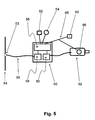
- FIG. 5 shows a use of a field device according to the invention Figure 1 to 4 ,
- the field device is a converter 50, which is connected to an electric motor 52 and controls or regulates this.
- the converter 50 is furthermore connected to a field bus 54, for example an AS-interface bus, more precisely a connecting line 55 connecting a slave 58 comprised by the converter 50 to the field bus 54 via a connection point 53.
- the slave 58 is thus integrated in the inverter 50; it is operated in transparent mode.
- a microprocessor which is designed as a controller 56 of the inverter 50, takes the forwarded by the slave data according to the arrangement in FIG. 3 and processes them using a state machine stored in it FIG.
- the controller 56 also serves the functionally typical for a drive or control of the motor 52, by controlling a power electronics connected to the latter 60.
- the microprocessor 11 off FIG. 3 So is advantageously integrated into the already necessary and therefore existing control 56 of the inverter 50.
- actuators 62 and sensors 64, 66 are connected directly or via a further bus 68, which are optionally integrated in the motor 52, as shown by way of example for sensor 66.
- the converter 50 is thus designed as a field device, as is advantageous for applications of the decentralized technique.
- 50 integrated in the converter, which allow use of the inverter 50 as a bus subscriber.
- the provision according to the invention of two logical slaves by a corresponding state machine in the controller 56 has the particularly advantageous effect of providing, on the one hand, binary data for the fieldbus 54 and the converter 50
- Control of actuators 62 or sensors 64, 66 are interchangeable and that on the other hand byte-oriented data, for example in the form of parameters for the inverter 50 or commands for operating the motor 52 or in the form of information about the state of inverter 50 or motor 52 can be transferred are.
- AS-interface bus instead of the AS-interface bus, another fieldbus, in particular CAN, CANopen, DeviceNet, Profibus, INTERBUS, Ethernet, real-time Ethernet, wireless LAN, EIB or LCN.
- AS-interface bus instead of the AS-interface bus, another fieldbus, in particular CAN, CANopen, DeviceNet, Profibus, INTERBUS, Ethernet, real-time Ethernet, wireless LAN, EIB or LCN.
Abstract
Description
Die Erfindung betrifft ein Verfahren zur sicheren Datenübertragung und ein Gerät, insbesondere ein Feldgerät oder einen Frequenzumrichter.The invention relates to a method for secure data transmission and a device, in particular a field device or a frequency converter.
Aus der
AS-Interface als ein bit-orientierter Feldbus auf der untersten Ebene der Automatisierungspyramide ist bekannt aus:
- der Publikation
R. Becker (Hrsg.): AS-Interface, die Lösung in der Automation, Gelnhausen (2002): ASlnternational Association, insbesondere Kapitel 3.2 - dem Internet-Nachschlagewerk de.wikipedia.org,
- der
DE 197 43 981 A1 - der Norm EN 50295,
- der Internetseite http://www.as-interface.com/whatisasi.asp,
- der Präsentation "The AS-Interface Innovation Step 3.0" der AS-International Association vom 28.06.2005 und
- der Präsentation "AS-Interface" http://www.emg.ing.tu-bs.de/pdf/IKF/AS-i_SS04.pdf.
- the publication
R. Becker (ed.): AS-Interface, the solution in automation, Gelnhausen (2002): ASlnternational Association, especially chapter 3.2 - the Internet reference book de.wikipedia.org,
- of the
DE 197 43 981 A1 - the standard EN 50295,
- the website http://www.as-interface.com/whatisasi.asp,
- the presentation "The AS-Interface Innovation Step 3.0" of the AS-International Association from 28.06.2005 and
- the presentation "AS-Interface" http://www.emg.ing.tu-bs.de/pdf/IKF/AS-i_SS04.pdf.
Moderne Feldgeräte, wie sie insbesondere in Anlagen mit dezentraler Steuerungstechnik Verwendung finden, benötigen aber oftmals zahlreiche Parameter, die zur Optimierung der Feldgerätefunktion variabel einstellbar sind.However, modern field devices, such as those used in systems with decentralized control technology, often require numerous parameters that can be variably set to optimize the field device function.
Moderne Feldgeräte können darüber hinaus oftmals Diagnose- und Serviceinformationen sammeln, die eine schnelle Problembeseitigung im Störungsfall unterstützen. Hierzu zählen elektronisch übermittelbare Daten nicht nur über das Produkt, wie Hersteller, Typenbezeichnung, Produktionsdatum, Firmware-Stand, sondern auch über den Betrieb, wie Betriebsstunden, Anzahl der Start-/Stop-Vorgänge, Überlastzustände und dergleichen mehr, aber auch zusätzliche Daten zur Gewährleistung sicherheitsgerichteter Anforderungen. In addition, modern field devices can often collect diagnostics and service information that helps to quickly resolve problems in the event of a malfunction. This includes electronically transmitted data not only about the product, such as manufacturer, type designation, production date, firmware status, but also about the operation, such as operating hours, number of start / stop operations, overload conditions and the like, but also additional data for Ensuring safety-related requirements.
Andere Feldgeräte, etwa zum Bedienen und Beobachten, weisen z.B. eine einfache Anzeige auf, auf der Messdaten ausgegeben werden und ein Tastenfeld, über das Kommandos an die Steuerung eingebbar sind. Auch hier sind verschiedene byte-orientierte und bit-orientierte Funktionen logisch einander zugeordnet, wobei erstere für die Anzeige und letzte für die Tasten zum Einsatz kommen.Other field devices, such as for operator control and observation, have e.g. a simple display on which measured data is output and a keypad, via which commands can be input to the controller. Again, different byte-oriented and bit-oriented functions are logically associated with each other, the former being used for display and last for the keys.
Um diesem Umstand Rechnung zu tragen, sind in der Spezifikation Version 3.0 Slave-Profile eingeführt worden, die sowohl über bit-orientierte als auch über byte-orientierte Datenaustauschmechanismen verfügen, siehe beispielsweise die zitierte Publikation AS-Interface, die Lösung in der Automation. Hier sei beispielhaft das Profil S-7.A.5 genannt. Bei diesem Profil werden je 2 Bit für einen seriellen Datenaustausch verwendet, es bleiben daher nur 1 oder 2 Bits für den schnellen bit-orientierten Datenaustausch übrig. Dies wiederum ist für viele Anwendungen - z.B. in der Antriebstechnik - zu wenig.In order to take this into account, version 3.0 of the specification specifies slave profiles that have both bit-oriented and byte-oriented data exchange mechanisms, see for example the cited publication AS-Interface, the solution in automation. Here is an example of the profile S-7.A.5 called. This profile uses 2 bits each for serial data exchange, leaving only 1 or 2 bits for fast bit-oriented data exchange. This in turn is for many applications - e.g. in drive technology - too little.
Dokument
Der Erfindung liegt die Aufgabe zugrunde, den Datenaustausch bei einem Bussystem in einfacher und fehlerarmer Weise weiterzubilden.The invention has for its object to further develop the data exchange in a bus system in a simple and low-error manner.
Erfindungsgemäß wird die Aufgabe bei dem Verfahren zur sicheren Datenübertragung nach den in Anspruch 1 und bei dem Gerät nach den in Anspruch 13 vorgegebenen Merkmalen gelöst.According to the invention, the object is achieved in the method for secure data transmission according to the features defined in
Das erfindungsgemäße Verfahren ist vorteilhaft einsetzbar bei einem als Busteilnehmer vorgesehenem Gerät, welches mittels eines Anschlusses mit einem Bus, insbesondere mit einem elektrischen Kabel, einer Stromschiene oder über eine Antenne mit Luft, verbunden ist, wobei Mittel zum Bereitstellen von zwei oder mehr Busteilnehmern umfasst sind und Mittel zum Zuordnen der über den Anschluss einströmenden und/oder ausgetauschten Daten an die zwei oder mehr Busteilnehmer umfasst sind. Derartige als Busteilnehmer vorgesehene Geräte werden auch als Feldgeräte bezeichnet. Vorzugsweise ist der Busteilnehmer zur Teilnahme an verschiedenartigen, aufeinander folgenden Buszyklen oder zur Kommunikation über verschiedene, getrennte Kommunikationskanäle ausgebildet. Vorteilig ist hierbei, dass über einen Anschluss zwei oder mehr Busteilnehmer an einen Bus anschließbar sind, was die Verkabelung vereinfacht. Auch können vorteilhaft durch die Bereitstellung mehrerer Busteilnehmer einerseits schnelle, bit-orientierte Daten und andererseits langsame, byte-orientierte, komplexe Daten ausgetauscht werden oder eine redundante Datenübertragung realisiert werden. Somit ist der Datenaustausch zwischen Master und Slave in einem Feldbus-System derart weitergebildet, dass je nach Anforderung verschiedene Datenaustauschmechanismen auf einfache und fehlerarme Weise einsetzbar sind. Von Vorteil ist weiter, dass ein Feldgerät eine Gruppe von Slaves enthält und somit über verschiedene Datenaustauschmechanismen unterschiedliche Datentypen oder zur Fehlerfeststellung mehrere Kopien einer jeden Daten- oder Informationseinheit mit einem Master austauschen kann. The method according to the invention can be used advantageously in a device provided as a bus subscriber, which is connected by means of a connection to a bus, in particular to an electrical cable, a busbar or via an aerial with air, wherein means for providing two or more bus users are included and means for associating the data flowing in through the port and / or exchanged data with the two or more bus subscribers. Such intended as a bus participants devices are also referred to as field devices. The bus subscriber is preferably designed to participate in various, consecutive bus cycles or to communicate via different, separate communication channels. It is advantageous here that two or more bus users can be connected to a bus via one connection, which simplifies the wiring. Advantageously, by providing a plurality of bus users, it is also possible to exchange fast, bit-oriented data and, on the other hand, slow, byte-oriented, complex data, or to implement redundant data transmission. Thus, the data exchange between the master and slave in a fieldbus system is developed such that depending on the requirements of different data exchange mechanisms can be used in a simple and low-error manner. A further advantage is that a field device contains a group of slaves and thus can exchange different data types or, for error detection, multiple copies of each data or information unit with a master via different data exchange mechanisms.
Eine vorteilhafte Ausgestaltung des an einem Bus angeschlossenen Geräts kann vorsehen, dass dieses in einem ersten Modus einen logischen Slave, insbesondere Busteilnehmer, realisiert, und in einem zweiten Modus mindestens zwei logische Slaves, insbesondere Busteilnehmer, realisiert. Somit wird vorteilhaft bewirkt, dass je nach Anforderungen, beispielsweise an den Datenaustausch, zwischen verschiedenen Modi gewechselt werden kann. Insbesondere ist somit beispielsweise für eine Initialisierung des Geräts oder die Integration in das Feldbussystem ein einfach handhabbarer Modus wählbar, während für einen komplexen Datenaustausch ein komplexer Modus mit mehreren Busteilnehmern wählbar ist. An advantageous embodiment of the device connected to a bus can provide that this realizes a logical slave, in particular bus subscriber, in a first mode, and realizes at least two logical slaves, in particular bus users, in a second mode. Thus, it is advantageously effected that it is possible to switch between different modes, depending on the requirements, for example on the data exchange. In particular, an easily manageable mode can thus be selected, for example, for initialization of the device or integration into the fieldbus system, while a complex mode with multiple bus users can be selected for a complex data exchange.
Bei einer weiteren vorteilhaften Ausgestaltung des Geräts ist im ersten Modus genau ein logischer Slave, insbesondere Busteilnehmer, realisiert. Von Vorteil ist dabei, dass die Inbetriebnahme, insbesondere Anmeldung im Feldbus-System oder Adresszuweisung, einfach vornehmbar ist.In a further advantageous refinement of the device , in the first mode exactly one logical slave, in particular bus subscriber, is realized. The advantage here is that the Commissioning, in particular registration in the fieldbus system or address assignment, is easily vornehmbar.
Bei einer weiteren vorteilhaften Ausgestaltung des Geräts ist der Bus ein Feldbus, insbesondere CAN, CAN-Open, DeviceNet, Profibus, INTERBUS, AS-interface, Ethernet, Wireless-LAN, EIB, LCN. Von Vorteil ist dabei, dass der Busteilnehmer an einen standardisierten Bus anschließbar ist. Somit ist die erfindungsgemäße Vorrichtung modular in handelsüblichen Anlagen einsetzbar, insbesondere in Anlagen mit dezentraler Technik.In a further advantageous embodiment of the device , the bus is a fieldbus, in particular CAN, CANopen, DeviceNet, Profibus, INTERBUS, AS-interface, Ethernet, wireless LAN, EIB, LCN. The advantage here is that the bus subscriber can be connected to a standardized bus. Thus, the device according to the invention can be used modularly in commercially available systems, in particular in systems with decentralized technology.
Die Erfindung ist besonders vorteilhaft einsetzbar bei Bussystemen, die wenigsten einen Master und mehrere Slaves umfassen, wobei der Master an die Slaves Adressen vergibt.The invention can be used particularly advantageously in bus systems which comprise at least one master and a plurality of slaves, wherein the master assigns addresses to the slaves.
Bei einer weiteren vorteilhaften Ausgestaltung des Geräts ist der erste Modus ein Standardadressiermodus, bei einer weiteren vorteilhaften Ausgestaltung ist der zweite Modus ein erweiterter Adressiermodus. Von Vorteil ist dabei, dass, insbesondere bei Anschluss an einen AS-interface-Bus, im ersten Modus eine Adresse zuweisbar ist, die im zweiten Modus für eine Mehrzahl von Busteilnehmern beziehungsweise logischen Slaves verwendbar ist, da im erweiterten Adressiermodus mit einer Adresse in den unterschiedlichen Zyklen unterschiedliche Slaves ansprechbar sind.In a further advantageous embodiment of the device , the first mode is a standard addressing mode, in a further advantageous embodiment, the second mode is an extended addressing mode. The advantage here is that, in particular when connected to an AS-interface bus, in the first mode, an address can be assigned, which can be used in the second mode for a plurality of bus subscribers or logical slaves because in the extended addressing mode with an address in the Different cycles different slaves are addressed.
Bei einer weiteren vorteilhaften Ausgestaltung umfasst das Gerät eine Umschaltlogik, die bei einem Wechsel von einer Standardadresse, insbesondere von einer Auslieferungsadresse oder von Adresse "0", auf einen anderen Adressen-Wert das Gerät vom ersten in den zweiten Modus versetzt. Mit der Standardadresse wird in dieser Schrift generell eine Adresse verstanden, mit welcher der Busteilnehmer im Auslieferungszustand, also vor Gebrauch im Bussystem, ausgerüstet ist. Oft wird hierzu die Adresse "0" verwendet, weshalb im Folgenden diese Bezeichnung der Einfachheit halber verwendet wird. Es sind jedoch auch andere Adressen als Standardadressen verwendbar. Wichtig ist allein, dass die Standardadresse von einem Master als solche durch die Konventionen des Protokolls erkennbar ist und die Erkennung einer Standardadresse die Ausführung eines Adressierungsverfahrens auslöst. Von Vorteil ist dabei, dass durch Standardvorgänge auf dem Bus ein Wechsel der Modi bewirkbar ist. Somit ist eine Erweiterung der Menge der über den Bus vermittelten Befehle und Kommandos vermeidbar. Bei einer weiteren vorteilhaften Ausgestaltung arbeitet das Gerät bei Zuweisung der Adresse "0" im ersten Modus und bei Zuweisung einer Adresse ungleich "0" im zweiten Modus. Von Vorteil ist dabei, dass ein ohnehin notwendiger Vorgang, nämlich die Adresszuweisung an ein durch Adresse "0" als an den Bus neu angeschlossen ausgewiesenes Gerät, für das Umschalten in den komplexeren Modus verwendbar ist. Somit ist die Adressvergabe in einem einfachen Verfahren durchführbar, durch einen Master oder mithilfe eines handelsüblichen Adressiergerätes. Besonders vorteilhaft bei der Wahl der Adresse "0" als funktionsunterscheidendes Merkmal ist, dass AS-interface-Slave bei Auslieferung diese Adresse belegen. Somit stellt sich das erfindungsgemäße Gerät bei Integration in ein AS-interface-Netzwerk bis zur Adressierung gegenüber dem Master als Standardslave dar. Für den Anwender besteht also vorteilhaft kein Unterschied zum Adressieren eines normalen Slaves, insbesondere gegebenenfalls eines AS-interface-Slaves. Nach Adressierung ist unmittelbar der zweite Modus bereitgestellt, der für den Hauptbetrieb des Feldgeräts vorgesehen ist. Weiter ist vorteilhaft die zugewiesene Adresse im zweiten Modus im erweiterten Adressiermodus, wie beispielsweise in der
Bei einer weiteren vorteilhaften Ausgestaltung des Geräts weisen die mindestens zwei logischen Slaves voneinander verschiedene Profile auf. Somit sind die realisierten Slaves für unterschiedliche Datenübertragungsmechanismen einsetzbar. Beispielsweise sind bit-orientierte Funktionen an einen Slave übertragbar und byte-orientierte Funktionen an einen weiteren Slave.In a further advantageous embodiment of the device , the at least two logical slaves have different profiles from each other. Thus, the realized slaves can be used for different data transmission mechanisms. For example, bit-oriented functions are transferable to a slave and byte-oriented functions to another slave.
Weitere vorteilhafte Merkmale des Geräts zum Anschluss an einen Bus können sein, dass das Gerät einen Rechner umfasst, wobei im Rechner die state machine mindestens zweier Busteilnehmer abgebildet ist. Von Vorteil ist dabei, dass zwei oder mehr Busteilnehmer und/oder logische Slaves realisierbar sind.Further advantageous features of the device for connection to a bus may be that the device comprises a computer, wherein the state machine of at least two bus users is mapped in the computer. The advantage here is that two or more bus participants and / or logical slaves can be realized.
Bei einer weiteren vorteilhaften Ausgestaltung umfasst das Gerät einen Slave-IC und den mit diesem verbundenen Rechner, insbesondere Mikroprozessor mit Speicher, wobei der Slave-IC im transparenten Modus verwendbar ist. Von Vorteil ist dabei, dass eine Kommunikation zwischen Bus und Mikroprozessor und eine Realisierung mehrerer Slaves einfach und kostengünstig ermöglicht ist.In a further advantageous embodiment, the device comprises a slave IC and the computer connected thereto, in particular microprocessor with memory, wherein the slave IC can be used in the transparent mode. The advantage here is that a communication between bus and microprocessor and a realization of multiple slaves is easy and inexpensive.
Bei einer weiteren vorteilhaften Ausgestaltung des Geräts ist der Busteilnehmer als AS-interface-Slave oder anderer Feldbus-Slave ausgebildet. Von Vorteil ist dabei, dass standardisierte Bus-Systeme einsetzbar sind, insbesondere bei Verwendung eines AS-interface-Busses.In a further advantageous embodiment of the device , the bus subscriber is designed as an AS-interface slave or other fieldbus slave. The advantage here is that standardized bus systems can be used, especially when using an AS-interface bus.
Das erfindungsgemäße Verfahren ist vorteilhaft kombinierbar mit einem Verfahren zur Adressierung eines als Busteilnehmer vorgesehenen Geräts, bei welchem zwei logische Slaves umfasst sind,
wobei
- das Gerät vor der Adressierung mit einer Standardadresse, insbesondere Adresse "0", versehen wird und in einem ersten Modus, insbesondere Standardadressiermodus, betrieben wird,
- dem Gerät eine andere Adresse zugewiesen wird,
- und dann das Gerät nach Adresszuweisung mindestens zwei logische Slaves realisiert.
in which
- the device is provided with a standard address, in particular address "0", before the addressing and is operated in a first mode, in particular standard addressing mode,
- the device is assigned a different address,
- and then the device realizes at least two logical slaves after address assignment.
Von Vorteil ist dabei, dass die Adressierung eines derartigen Geräts mit jedem bereits auf dem Markt befindlichen Adressiergerät durchführbar ist. Von Vorteil ist weiterhin, dass die Adresse "0" die Standardadresse bei Auslieferung oder Neuanmeldung im Bussystem eines Busteilnehmers darstellt und standardmäßig eine Adresszuweisung durch einen Master nach sich zieht. Insbesondere muss der Master oder alternativ der Anwender eines solchen Geräts nur einen Adressiervorgang für die mindestens zwei logischen Slaves durchführen.The advantage here is that the addressing of such a device can be carried out with any addressing device already on the market. Another advantage is that the address "0" represents the default address at the time of delivery or new application in the bus system of a bus station and by default an address assignment by a master entails. In particular, the master or alternatively the user of such a device only has to perform an addressing process for the at least two logical slaves.
Besonders günstig ist es dabei, wenn die Slaves im erweiterten Adressiermodus mit der zugewiesenen Adresse alternierend jeweils in aufeinander folgenden Zyklen als A-Adresse beziehungsweise B-Adresse angesprochen werden. Hierbei ist vorteilhaft, dass im Slave im Standardadressiermodus der gleiche Adressraum belegbar ist wie in den mindestens zwei logischen Slaves beispielsweise im erweiterten Adressiermodus. Der Adressvorgang ist somit vorteilhaft durchführbar, ohne dass die Gefahr der Doppeladressierung besteht. Das erfindungsgemäße Verfahren ist vorteilhaft mit einem Umrichter ausführbar, bei welchem ein Gerät zum Anschluss an einen Bus integriert ist. Von Vorteil ist dabei, dass im Umrichter Mittel zur Kommunikation mit einem Bussystem vorsehbar sind. Somit ist der Umrichter vorteilhaft in Anlagen mit dezentraler Technik einsetzbar. It is particularly advantageous if the slaves are addressed in the extended addressing mode with the assigned address alternately in successive cycles as A-address or B-address. It is advantageous that in the slave in the standard addressing mode, the same address space is assignable as in the at least two logical slaves, for example in the extended addressing mode. The address process is thus advantageously feasible without the risk of double addressing exists. The method according to the invention can advantageously be implemented with an inverter in which a device is integrated for connection to a bus. The advantage here is that in the converter means for communication with a bus system are providable. Thus, the inverter is advantageously used in systems with decentralized technology.
Bei einer weiteren vorteilhaften Ausgestaltung des Umrichters ist der Mikroprozessor des Geräts zum Anschluss an einen Bus in die Steuerung des Umrichters, insbesondere in die Ansteuerung der Leistungselektronik des Umrichters, integriert. Von Vorteil ist dabei, dass die ohnehin in der Steuerung des Umrichters vorhandene Rechenkapazität nutzbar ist für die Realisierung der logischen Slaves. Dies bewirkt vorteilhaft eine kompakte Bauform mit wenigen Komponenten.In a further advantageous embodiment of the inverter, the microprocessor of the device for connection to a bus in the control of the inverter, in particular in the control of the power electronics of the inverter, integrated. The advantage here is that the already existing in the control of the inverter computing capacity is available for the realization of the logical slaves. This advantageously causes a compact design with few components.
Bei einer weiteren vorteilhaften Ausgestaltung des Umrichters sind Anschlussmittel für den Anschluss von Aktoren und/oder Sensoren und/oder einem Bus, beispielsweise MOVILINK®, und/oder Schaltausgänge umfasst, wobei diese Anschlussmittel und/oder Schaltausgänge vom Bus ansteuerbar beziehungsweise auslesbar sind. Von Vorteil ist dabei, dass der Umrichter mit den integrierten Mitteln zusätzlich zu seiner namensgebenden Funktion als Slave zur Abarbeitung einfachster Funktionen und auch als Knoten im Bus-Netzwerk einsetzbar ist.In a further advantageous embodiment of the converter connecting means for the connection of actuators and / or sensors and / or a bus, for example MOVILINK ® , and / or switching outputs includes, these connection means and / or switching outputs are controlled by the bus or read. The advantage here is that the inverter can be used with the integrated means in addition to its eponymous function as a slave for processing the simplest functions and as a node in the bus network.
Wichtige Merkmale der Erfindung eines Verfahrens zur sicheren Datenübertragung, wobei ein als Busteilnehmer vorgesehenes Gerät vorgesehen ist, sind, dass
- das Gerät vor der Adressierung mit einer Standardadresse, insbesondere Adresse "0", versehen wird und in einem ersten Modus, insbesondere Standardadressiermodus, betrieben wird und einen logischen Slave realisiert,
- dem Gerät eine andere Adresse zugewiesen wird,
- und dann das Gerät nach Adresszuweisung mindestens zwei logische Slaves realisiert,
wobei die in dem Gerät nach Adressierung realisierten mindestens zwei logischen Slaves zur redundanten, insbesondere sicherheitsgerichteten, Datenkommunikation mit dem Bus verwendet werden. Somit lassen sich Daten sicher über einen von außen gestörten Kommunikationskanal, beispielsweise einer Starkstromleitung und/oder einem Kanal mit zwischengeschaltetem induktiven oder kapazitiven Koppelelement, nutzen, ohne das eine aufwendige Neukonstruktion erforderlich ist.
- the device is provided with a standard address, in particular address "0", before the addressing and is operated in a first mode, in particular standard addressing mode, and realizes a logical slave,
- the device is assigned a different address,
- and then the device realizes at least two logical slaves after address assignment,
wherein the implemented in the device after addressing at least two logical slaves for redundant, in particular safety-related, data communication with the bus are used. Thus, data can be safely via a disturbed communication channel outside, for example, a power line and / or a channel with interposed inductive or capacitive coupling element, use without a costly redesign is required.
Bei einer vorteilhaften Ausgestaltung tauschen die in dem Slave nach Adressierung realisierten mindestens zwei logischen Slaves über jeweils einen Kommunikationskanal Daten aus, wobei Daten redundant übertragen werden, insbesondere also in jedem Kommunikationskanal die Daten einen identischen Informationsgehalt aufweisen. Die Kommunikationskanäle können zeitlich parallel oder nacheinander betrieben werden.In an advantageous embodiment, the at least two logical slaves implemented in the slave exchange data via one communication channel in each case, with data being transmitted redundantly, ie, in each communication channel, the data having an identical information content. The communication channels can be operated in parallel or in succession.
Bei einer vorteilhaften Ausgestaltung ist mindestens einer der mindestens zwei logischen Slaves ein sicherheitsgerichteter Teilnehmer. Von Vorteil ist dabei, dass selbst das einem Teilnehmer übermittelte Signal auf Übertragungsfehler prüfbar ist. Vorzugsweise werden sicherheitsgerichtete Merkmale wie in Dietmar Reinert; Michael Schaefer (Hrsg.): Sichere Bussysteme für die Automation, Heidelberg: Hüthig, 2001, beschrieben realisiert.In an advantageous embodiment, at least one of the at least two logical slaves is a safety-related subscriber. The advantage here is that even the signal transmitted to a subscriber is testable for transmission errors. Preferably, safety-related features are as in Dietmar Reinert; Michael Schaefer (ed.): Safe bus systems for automation, Heidelberg: Hüthig, 2001, described realized.
Vorzugsweise kann vorgesehen sein, dass der sicherheitsgerichtete Teilnehmer zur Übermittelung seiner Nutzdaten, die beispielsweise auch die Adresse umfassen, diese Nutzdaten in einer Sicherheitsschicht Sicherheitsprozeduren zur Authentifizierung und/oder zur Generierung von Sicherungscodes wie z.B. CRC unterwirft. Somit werden an die Nutzdaten zusätzliche, sicherheitsrelevante Daten angehängt und die so verpackten Daten an nicht-sicherheitsgerichtete Transportschichten, insbesondere die Hardware des Bussystems, übergeben.Preferably, it may be provided that the safety-related subscriber for transmitting his user data, which also includes, for example, the address, these user data in a security layer security procedures for authentication and / or for generating security codes such. CRC submits. Thus, additional, safety-relevant data are appended to the payload and the data thus packed is transferred to non-safety-related transport layers, in particular the hardware of the bus system.
Bei Verwendung eines Codegenerators in einem sicherheitsgerichteten Slave, durch den beispielsweise ein dynamisiertes "frei"-Signal erzeugt wird, kann zur Reduzierung der Übertragungsfehlerrate vorgesehen sein, dass jeder logische Slave an einen separaten Codegenerator angeschlossen ist und/oder dass für jeden logischen Slave nach einer separaten Codetabelle codiert wird.When using a code generator in a safety-related slave, through which, for example, a dynamized "free" signal is generated, can be provided to reduce the transmission error rate that each logical slave is connected to a separate code generator and / or that for each logical slave after a coded separate code table.
Bei einer vorteilhaften Ausgestaltung wird ein Bussystem mit mindestens zwei Zyklen betrieben, wobei die Busteilnehmer als erfindungsgemäße Geräte mit zwei oder mehreren logischen Slaves ausgebildet sind und in einem ersten Zyklus Informationen gesendet werden, die in dem folgenden, zweiten Zyklus wiederholt werden. Jeder logische Slave stellt somit die Empfangs- oder Sendestelle eines Kommunikationskanals dar, wobei die Kommunikationskanäle entsprechend der Abfolge der Zyklen nacheinander oder parallel aktiviert und genutzt werden. Von Vorteil ist dabei, dass sowohl der Aufbau des Busnetzwerks als auch die Adressierung als auch die Informationsübertragung so verlaufen, als ob ein einfacher Bus vorläge, und die Informationen der Datenkommunikation redundant übertragen werden. Ein Anwendungstechniker muss demnach beim Netzaufbau keine Besonderheiten beachten.In an advantageous embodiment, a bus system is operated with at least two cycles, wherein the bus participants are designed as devices according to the invention with two or more logical slaves and information is sent in a first cycle, which are repeated in the following second cycle. Each logical slave thus represents the receiving or transmitting station of a communication channel, the communication channels according to the sequence of cycles successively or in parallel activated and used. The advantage here is that both the structure of the bus network as well as the addressing and the information transmission run as if a simple bus is present, and the information of the data communication is transmitted redundantly. An application engineer therefore does not have to consider any special features when setting up the network.
Beispielsweise kann es vorgesehen sein, dass die logischen Slaves zur Reduzierung von Übertragungsfehlern, die aufgrund von Wiederholungen von nicht mehr aktuellen Nachrichten zu falschen Zeit, von Nachrichtenverlust, von fehlerhaftem Einfügen von Nachrichten, von Veränderung der Abfolge von Nachrichten, von Verzögerung von Nachrichten und/oder von Verfälschungen von Nachrichten auftreten, ausgebildet sind.For example, the logical slaves may be designed to reduce transmission errors due to repetitions of out-of-date messages at the wrong time, message loss, erroneous insertion of messages, change in the sequence of messages, delay of messages, and / or corrupt messages are formed.
In einer besonders einfach realisierbaren Ausgestaltung senden beide Slaves dieselbe Information, so dass bei fehlender Übereinstimmung ein Übertragungsfehler bzw. ein Kodierungsfehler erkennbar istIn a particularly simple embodiment, both slaves send the same information, so that if there is no match, a transmission error or a coding error can be detected
Zur Erkennung von Übertragungsfehlern kann beispielsweise ein Slave zur Übertragung von laufenden Nummern, welche die Nachrichten des jeweils anderen Slave fortlaufend nummerieren, verwendet werden, oder zur Übertragung einer Zeitmarke, die den Zeitpunkt der Nachrichtenabsendungen des jeweils anderen Slave absolut oder relativ markieren. Hierdurch werden vorteilhaft Vertauschungen von Nachrichten und die Einfügung von Nachrichten erkennbar.For example, to detect transmission errors, a slave may be used to transmit consecutive numbers consecutively numbering the messages of the other slave, or to transmit a timestamp which marks the time of the message sendings of the other slave in absolute or relative terms. This advantageously identifies exchanges of messages and the insertion of messages.
Alternativ oder zusätzlich kann vorgesehen sein, dass wenigstens ein Slave zur Übermittelung einer Zeiterwartung verwendet wird, welche die Gültigkeitsdauer einer Nachricht des jeweils anderen Slave charakterisiert. Bei Überschreitung des vorgegebenen Wertes bis zum Eingang beim Empfänger ist vorzugsweise vorgesehen, dass der Empfänger eine Fehlermeldung generiert und/oder die empfangene Nachricht ignoriert.Alternatively or additionally, it can be provided that at least one slave is used to transmit a time expectancy, which characterizes the validity period of a message of the other slave. When exceeding the predetermined value to the receipt at the receiver is preferably provided that the receiver generates an error message and / or ignores the received message.
Zur Verminderung von Übertragungsfehler kann vorgesehen sein, dass ein Slave zum Absenden einer Rückmeldung über Erhalt und/oder Inhalt der Nachricht an den Master eingerichtet ist. Beispielsweise können die Daten wiederholt werden, die vom Master gesendet wurden, um diesem die Überprüfung des richtigen Empfangs zu ermöglichen.To reduce transmission errors can be provided that a slave for sending a feedback on receipt and / or content of the message to the master is set up. For example, the data sent by the master may be repeated to allow it to verify the correct reception.
Zusätzlich oder alternativ kann vorgesehen sein, dass ein logischer Slave zur Übermittlung einer Nachrichtenkennung eingerichtet ist, mit welchem der Sender, also der jeweils andere logische Slave, authentifizierbar ist. Von Vorteil ist dabei, dass am Master die Einfügung von Nachrichten durch nicht autorisierte Sender oder durch Störeinkopplungen erkennbar ist.Additionally or alternatively, it can be provided that a logical slave is set up for the transmission of a message identifier with which the transmitter, that is to say the respective other logical slave, can be authenticated. The advantage here is that at the master insertion of messages by unauthorized transmitters or by sturgeon couplings is recognizable.
Die zweikanalige, redundante Buskommunikation in den alternierenden Zyklen ist außerdem dazu nutzbar, die gesendeten und empfangenen Nachrichten zwischen Slave und Master kreuzweise zu vergleichen und so auf Übertragungsfehler zu prüfen. Bei erkannter Abweichung muss ein Fehler der Übertragung, der Empfängereinheit und/oder der Sendereinheit vorliegen. Von Vorteil ist dabei, dass fehlerhafte Wiederholung, Verlust, fehlerhafte Einfügung, falsche Abfolge und Verfälschung von Nutzdaten erkennbar ist.The two-channel, redundant bus communication in the alternating cycles can also be used to cross-compare the sent and received messages between slave and master and thus to check for transmission errors. If a deviation is detected, there must be an error in the transmission, the receiver unit and / or the transmitter unit. The advantage here is that erroneous repetition, loss, incorrect insertion, incorrect sequence and falsification of user data is recognizable.
Bei einer vorteilhaften Ausgestaltung vergleicht jeder Busteilnehmer seine in dem ersten Zyklus empfangenen Informationen mit den im zweiten Zyklus empfangenen Informationen.In an advantageous embodiment, each bus subscriber compares its information received in the first cycle with the information received in the second cycle.
Bei einer vorteilhaften Ausgestaltung kann es vorgesehen sein, dass ein Bussystem mit mindestens zwei Zyklen betrieben wird und in einem Zyklus Nutzdaten und im jeweils vorangehenden oder folgenden Zyklus Prüfdaten übermittelt werden. Von Vorteil ist dabei, dass die in einem Zyklus, insbesondere von einem logischen Slave, übermittelten Daten im folgenden Zyklus oder durch Daten aus dem vorangehenden Zyklus verifizierbar sind, wobei nicht nur der Informationsgehalt, sondern andere Fehlerquellen überwachbar sind. Beispielsweise kann anhand einer laufenden Nummer der Nutzdaten eine Wiederholung, ein Verlust, eine Einfügung, auch durch unbefugte oder defekte Dritte, und eine falsche Abfolge erkannt werden. Durch eine Zeitmarke für den Sendezeitpunkt der Nutzdaten sind dagegen eine Wiederholung, eine falsche Abfolge und eine Verzögerung erkennbar. Eine Zeiterwartung für die Dauer der Gültigkeit der Nutzdaten ist zur Erkennung von Verzögerungen bei der Übertragung einsetzbar. Eine Empfangsbestätigung mit der Wiederholung einer zuvor erhaltenen Nachricht, insbesondere des Masters, ermöglicht die Detektion von Einfügungen, Verlusten oder Nachrichtenerfälschungen und verhindert die Kopplung von sicherheitsgerichteten mit nicht-sicherheitsgerichteten Nachrichten. Eine Kennung des Senders und/oder des Empfängers verhindert Einfügungen und die Kopplung von sicherheitsgerichteten mit nicht-sicherheitsgerichteten Nachrichten, beispielsweise mit von sonstigen Slaves im Bus ohne sicherheitsgerichtete Ausgestaltung abgegebenen Nachrichten. Diese Maßnahmen sind vorteilhaft mit Maßnahmen zur Datensicherung, beispielsweise durch Prüfsummen und dergleichen, kombinierbar.In an advantageous embodiment, it can be provided that a bus system is operated with at least two cycles and test data are transmitted in one cycle of user data and test data in the respective preceding or following cycle. It is advantageous here that the data transmitted in one cycle, in particular by a logical slave, can be verified in the following cycle or by data from the preceding cycle, whereby not only the information content but also other error sources can be monitored. For example, a repetition, a loss, an insertion, even by unauthorized or defective third parties, and a wrong sequence can be recognized on the basis of a serial number of the user data. By a timestamp for the transmission time of the user data, however, a repetition, a wrong sequence and a delay are recognizable. A time expectancy for the period of validity of the payload is to detect delays in the Transfer applicable. An acknowledgment of receipt with the repetition of a previously received message, in particular of the master, enables the detection of insertions, losses or message falsifications and prevents the coupling of safety-related messages with non-safety-related messages. An identifier of the transmitter and / or the receiver prevents insertions and the coupling of safety-related messages with non-safety-related messages, for example with messages issued by other slaves in the bus without a safety-related configuration. These measures can be advantageously combined with measures for data backup, for example by checksums and the like.
Bei einer vorteilhaften Ausgestaltung führt der Busteilnehmer, ein Busmaster und/oder ein Sicherheitsmonitor eine Fehlerroutine aus, wenn die verglichene Information nicht übereinstimmt und/oder wenn anhand der Prüfdaten ein Übertragungsfehler erkannt wird. Eine solche Fehlerroutine ist beispielsweise eine Rückmeldung an einen Busmaster, worauf die betreffende Information noch einmal gesendet wird. Eine solche Fehlerroutine ist beispielsweise auch der Übergang in einen sicheren Modus, etwa die Weitergabe des Befehls sicherer Halt an einen Motor, wenn der Slave mit dem Motor verbunden ist. Werden mehr als zwei Kommunikationskanäle verwendet, so wird vorzugsweise dann eine Fehlerroutine ausgeführt, wenn nicht mit genügend Sicherheit das richtige Datensignal rekonstruiert werden kann. Beispielsweise kann die ausgetauschte Information so auf drei Kommunikationskanäle verteilt werden, dass bei Ausfall eines Kanals die vollständige Information aus zwei Kanälen gewonnen werden kann, etwa nach Art eines RAID- oder redundant array of independent disks-Systems. Unter einem Sicherheitsmonitor wird hierbei ein Gerät verstanden, welches den Nachrichtenaustausch über den Bus überwacht, ohne an der Kommunikation teilzunehmen, und welches bei Abweichungen von Festlegungen, die zur Umsetzung von Sicherheitskonzepten vorgesehen sind, eine sichere Abschaltung oder die Ausgabe einer Fehlermeldung oder eine sonstige, sicherheitsrelevante Aktion einleitet.In an advantageous embodiment, the bus user, a bus master and / or a safety monitor executes an error routine if the information being compared does not match and / or if a transmission error is detected on the basis of the test data. Such an error routine is, for example, a feedback to a bus master, whereupon the relevant information is sent again. Such a fault routine is also, for example, the transition to a safe mode, such as the transfer of the safe stop command to a motor when the slave is connected to the motor. If more than two communication channels are used, an error routine is preferably then executed if the correct data signal can not be reconstructed with sufficient certainty. For example, the exchanged information can be distributed to three communication channels so that if one channel fails, the complete information can be obtained from two channels, such as a RAID or redundant array of independent disks system. A security monitor is here understood to mean a device which monitors the exchange of messages via the bus without participating in the communication, and which in the event of deviations from stipulations intended for implementation of security concepts, a secure shutdown or the issuing of an error message or another, introduces security-related action.
Zum Ausführen des erfindungsgemäßen Verfahrens kann ein Gerät vorgesehen sein, an welchem eine Umschaltlogik ausgebildet ist, die bei einem Wechsel von einer Standardadresse, insbesondere von einer Auslieferungsadresse oder von Adresse "0", auf einen anderen Adressen-Wert das Gerät von einem ersten in einen zweiten Betriebsmodus versetzt, wobei das Gerät im ersten Modus einen logischen Slave realisiert und das Gerät im zweiten Modus zwei logische Slaves realisiert.For carrying out the method according to the invention, a device may be provided on which a switching logic is formed which, when changing from a standard address, in particular from a delivery address or address "0", to a different address value, the device from a first to a first second In the first mode, the device realizes a logical slave and the device realizes two logical slaves in the second mode.
Bei diesem Gerät kann vorteilhaft vorgesehen sein, dass das Gerät einen Slave-IC und den mit diesem verbundenen Rechner, insbesondere Mikroprozessor mit Speicher, umfasst, wobei der Slave-IC im transparenten Modus verwendbar ist, insbesondere wobei der Mikroprozessor des Geräts zum Anschluss an einen Bus in die Steuerung des Umrichters, insbesondere in die Ansteuerung der Leistungselektronik des Umrichters, integriert ist, und/oder der Rechner von einem Umrichter oder einer Steuerung umfasst ist, insbesondere der Rechner zur Steuerung und/oder Regelung von Aktoren, Elektromotoren oder dergleichen vorgesehen ist, insbesondere wobei das Gerät ein Umrichter ist, in welchen ein Gerät zum Anschluss an einen Bus integriert ist, und/oder Anschlussmittel für den Anschluss von Aktoren und/oder Sensoren und/oder einem Bus, beispielsweise MOVILINK®-Bus, und/oder Schaltausgänge umfasst sind, wobei diese Anschlussmittel und/oder Schaltausgänge vom Bus ansteuerbar beziehungsweise auslesbar sind.In this device can be advantageously provided that the device comprises a slave IC and connected thereto computer, in particular microprocessor with memory, wherein the slave IC is used in the transparent mode, in particular wherein the microprocessor of the device for connection to a Bus is integrated into the control of the inverter, in particular in the control of the power electronics of the inverter, and / or the computer is comprised of a converter or a controller, in particular the computer for controlling and / or regulating actuators, electric motors or the like is provided in particular wherein the device is an inverter in which a device is integrated for connection to a bus, and / or connection means for the connection of actuators and / or sensors and / or a bus, for example MOVILINK ® -Bus, and / or switching outputs are included, these connection means and / or switching outputs can be controlled or read by the bus r are.
Weitere Vorteile ergeben sich aus den Unteransprüchen. Die Erfindung ist nicht auf die Merkmalskombination der Ansprüche beschränkt. Für den Fachmann ergeben sich weitere sinnvolle Kombinationsmöglichkeiten von Ansprüchen und/oder einzelnen Anspruchsmerkmalen und/oder Merkmalen der Beschreibung und/oder der Figuren, insbesondere aus der Aufgabenstellung und/oder der sich durch Vergleich mit dem Stand der Technik stellenden Aufgabe.Further advantages emerge from the subclaims. The invention is not limited to the combination of features of the claims. For the skilled person, further meaningful combination options of claims and / or individual claim features and / or features of the description and / or figures, in particular from the task and / or by posing the task by comparison with the prior art task.
- 11
- Feldgerätfield device
- 22
- AS-i-LeitungAS i cable
- 33
- Slaveslave
- 3A3A
- erster Slavefirst slave
- 3B3B
- zweiter Slavesecond slave
- 44
- Anschlussleitungconnecting cable
- 55
- interne Leitunginternal line
- 66
- KontaktContact
- 77
- interne Leitunginternal line
- 88th
- Anschlussconnection
- 1010
- Slave-ICSlave IC
- 1111
- Mikroprozessormicroprocessor
- 12, 13, 1412, 13, 14
- interne Datenleitunginternal data line
- 3030
- Zustand im ersten ModusCondition in the first mode
- 3131
- RESET-SignalRESET signal
- 3232
- Standardadressierungs-SignalStandard addressing signal
- 3333
- Zustand im zweiten ModusState in the second mode
- 3434
- weiterer Zustand im zweiten Modusanother condition in the second mode
- 3535
- Buskommando, Sensordatum oder AktorbefehlBus command, sensor data or actuator command
- 5050
- Umrichterinverter
- 5252
- Motorengine
- 5353
- Anschlusspunktconnection point
- 5454
- Feldbusfieldbus
- 5555
- Anschlussleitungconnecting cable
- 5656
- Steuerungcontrol
- 5858
- Slaveslave
- 6060
- Leistungselektronikpower electronics
- 6262
- Aktoractuator
- 64, 6664, 66
- Sensorsensor
- 6868
- Busbus
- 7070
- Applikationsmodulapplication module
- 7171
- virtueller Slavevirtual slave
- 7272
- Slaveslave
- 7373
- Slaveslave
- 7474
- Slaveslave
- 7575
- virtueller Slavevirtual slave
- 7676
- virtueller Slavevirtual slave
- 7777
- Systembussystem
- 7878
- EnergiebusEnergy Bus
Die Erfindung wird nun anhand von Abbildungen näher erläutert:
- Es zeigt:
-
Figur 1 -
Figur 2 -
Figur 3 -
Figur 4 -
Figur 5
-
- It shows:
-
FIG. 1 the functional diagram of an inventive field device after assignment of the address "0", -
FIG. 2 the functional diagram of a field device according to the invention after assignment of an address other than "0", -
FIG. 3 schematically a field device according to the invention, -
FIG. 4 the state machine of a microprocessor according to the invention, -
FIG. 5 a converter with motor as a field device according to the invention.
-
Das Feldgerät 1 ist mit einer AS-interface-Leitung 2 über eine Anschlussleitung 4 und einen Anschluss 8 an einem Anschlusspunkt verbunden. Es nimmt über diese Anschlussleitung 4 am AS-interface-Netzwerk so teil, als wären die Anschlussleitungen 4 über innere Leitungen 5 mit einem Slave 3 verbunden, der ein Standardprofil, beispielsweise das Profil S-7.F.F, aufweist. Der Slave 3 und die inneren Leitungen 5 sind dabei virtuell, d.h. das Feldgerät 1 simuliert die dargestellte Funktion.The
Ein ebenfalls an die AS-interface-Leitung angeschlossener Master kann nun das Feldgerät 1 anhand der Adresse "0" als neuen Teilnehmer erkennen und ihm in AS-interface-typischer Weise, wie es beispielsweise in der
Das Feldgerät 1 ist mit einer AS-interface-Leitung 2 über eine Anschlussleitung 4 an einem Anschluss 8 in einem Anschlusspunkt verbunden. Es nimmt über diese Anschlussleitung am AS-interface-Netzwerk im Unterschied zu dem in
Das AS-interface-Netzwerk wird nun im erweiterten Adressiermodus betrieben, und der Slave 3A spricht auf die Adresse des Feldgeräts 1 im A-Zyklus an, während der Slave 3B auf die Adresse des Feldgeräts 1 im B-Zyklus anspricht.The AS-interface network is now operated in the extended addressing mode, and the
Das Feldgerät 1 simuliert also den Anschluss zweier Slaves 3A und 3B an das AS-interface-Netzwerk, wobei Slave 3A die Adresse des Feldgeräts 1 als A-Adresse verwendet, während Slave 3B diese Adresse als B-Adresse benutzt. Aus einem logischen Slave bei Adresse "0" werden also zwei oder mehr logische Slaves mit beliebig vorgebbaren Profilen, wenn die Adresse ungleich "0" ist.The
Somit sind zwei Kommunikationskanäle verwendbar, über die identische Information redundant übertragen werden kann, wobei ein Kommunikationskanal von Slave 3A, der andere Kommunikationskanal von Slave 3B ausgewertet oder mit Signalen beaufschlagt wird. Slave 3A und Slave 3B vergleichen ihre jeweils empfangenen Daten und führen eine Fehlerroutine aus, wenn Datenungleichheit festgestellt wird. Jeder Kommunikationskanal ist durch einen Buszyklus realisiert.Thus, two communication channels can be used over which identical information can be transmitted redundantly, wherein a communication channel of
Bei einer Anwendung des beschriebenen Ausführungsbeispiels dienen die logischen Slaves zur Übertragung von 1 Bit Nutzinformation, welche die möglichen Bedeutungen "frei" für logisch 1 und "nicht frei" für logisch 0 haben und welche die sicherheitsgerichteten Schaltsignale eines Schutzschalters, beispielsweise eine Lichtgitters, eines NOT-AUS-Schalters oder Kontaktschalters, beschreiben.In an application of the described embodiment, the logical slaves are used to transmit 1 bit payload, which have the possible meanings "free" for logical 1 and "not free" for logical 0 and which the safety-related switching signals of a circuit breaker, such as a light grid, a NOT -AUS switch or contact switch, describe.
Im Zustand "nicht frei", also beispielsweise im Zustand "NOT-AUS betätigt" oder "Lichtgitter durchbrochen", liegt an den vier Eingangsbits jedes logischen Slaves der Wert (0,0,0,0) statisch an. Im Zustand "frei", also beispielsweise im Zustand "NOT-AUS nicht betätigt" oder "Lichtgitter nicht durchbrochen", wird dagegen an den vier Eingangsbits mit jedem Zyklus ein Wert angelegt, der wenigstens eine 1 aufweist, wobei die Werte eine periodisch wiederholte Abfolge bilden, bei denen kein Wert innerhalb einer Periode einem anderen gleicht. Diese Abfolge von Werten ist dem Master bekannt, wobei für jeden logischen Slave 3A, 3B eine andere Abfolge definiert ist. Im einfachsten Fall wechseln die beiden logischen Slaves 3A, 3B im Gegentakt zwischen zwei Werten. Hier ist sogar ein Codegenerator verzichtbar.In the state "not free", for example in the state "EMERGENCY STOP actuated" or "light curtain interrupted", the value (0,0,0,0) is statically present at the four input bits of each logical slave. In the state "free", for example in the state "EMERGENCY STOP not actuated" or "light grid not broken", a value is applied to the four input bits with each cycle having at least one 1, the values being a periodically repeated sequence in which no value is equal to another within one period. This sequence of values is known to the master, with a different sequence being defined for each
Somit erkennt der Master den Zustand "nicht frei" genau dann, wenn beide logischen Slaves 3A, 3B in ihrem Zyklus jeweils (0,0,0,0) anlegen, ansonsten erkennt der Master den Zustand "nicht frei" und kann, wenn die "nicht frei"-Signale wenigstens eines logischen Slaves von der vorgegebenen Abfolge abweichen, sogar die fehlerhafte Übertagung feststellen.Thus, the master detects the state "not free" if and only if both
Bei einem Ausführungsbeispiel wird für die Definition der beschriebenen Abfolge von Werten für den Zustand "nicht frei" ein Codegenerator verwendet, der auf eine Codierungstabelle zugreift. Für jeden logischen Slave wird hierbei eine separate Tabelle verwendet, wobei in einer Weiterbildung auch die Codegeneratoren getrennt ausgeführt sind. Durch die Verwendung von unterschiedlichen Codierungstabellen wird die Wahrscheinlichkeit, dass im Zustand "nicht frei", beispielsweise durch Störeinkopplungen oder Verfälschungen, der Zustand "frei" erreicht wird, weiter verringert.In one embodiment, to define the described sequence of values for the "not free" state, a code generator accessing a coding table is used. For each logical slave in this case a separate table is used, wherein in a development, the code generators are executed separately. By using different coding tables, the probability that the state "not free" is reached in the state "not free", for example due to interference couplings or distortions, is further reduced.
Bei einem weiteren erfindungsgemäßen Ausführungsbeispiel simuliert das Feldgerät 1 den Anschluss von drei, vier oder mehr Slaves über die Anschlussleitung 4, wenn ihm nicht die Adresse "0" zugewiesen wurde. Für die Simulation von mehr als zwei Slaves werden dem Feldgerät mehr als eine Adresse zugewiesen, die in Analogie zu dem Beispiel von
In diesem Fall ist wieder jeder logische Slave einem Kommunikationskanal zugeordnet. Die Information wird nun so redundant aufgeteilt, dass der volle Informationsgehalt rekonstruierbar ist, selbst wenn ein Kommunikationskanal ausfällt oder gestört wird. Die logischen Slaves vergleichen ihr jeweiliges Empfangsergebnis untereinander und stellen im Fall einer Abweichung mindestens eines Kommunikationskanals von den anderen fest, ob sich mit einer Untermenge der Kommunikationskanäle, also der empfangenen Daten der einzelnen logischen Slaves, eine widerspruchsfreie Information zusammengesetzt werden kann. Ist dies der Fall, wird eine erste Fehlerroutine ausgeführt, die empfangene Information jedoch trotzdem ausgewertet. Ist dies nicht der Fall, wird eine zweite Fehlerroutine ausgeführt und in einen sicheren Betriebsmodus, beispielsweise in einen sicheren Halt, gewechselt. Werden mit der ersten Fehlerroutine Signale an einen Busmaster gegeben, so zählt dieser die eingegangenen Signale und wechselt in einen Modus reduzierter Übertragungsrate, falls ein Grenzwert überschritten wird.In this case, again every logical slave is assigned to a communication channel. The information is now divided redundantly so that the full information content can be reconstructed, even if a communication channel fails or is disturbed. The logical slaves compare their respective reception result with each other and determine in the case of a deviation of at least one communication channel from the other, whether with a subset of the communication channels, ie the received data of the individual logical slaves, a consistent information can be assembled. If this is the case, a first error routine is executed, but the received information is nevertheless evaluated. If this is not the case, a second error routine is executed and changed to a safe operating mode, for example to a secure stop. If signals are given to a bus master with the first error routine, this counts the received signals and changes to a mode of reduced transmission rate if a limit value is exceeded.
Der zweite Modus umfasst diesen Zustand 33 und weitere Zustände 34, die mindestens die möglichen Zustände zweier logischer Slaves 3A, 3B umfassen. Insbesondere beschreibt also der Zustand 33 zwei logische Slaves, die im erweiterten Adressiermodus betreibbar sind, ein jeder in einem der beiden Zyklen und mit der durch das Standardadressierungs-Signal 32 zugewiesenen Adresse. Zwischen diesen Zuständen 33, 34 werden durch Buskommandos, Daten von an den Mikroprozessor angeschlossenen Sensoren oder Aktoren oder durch die Abgabe von Kommandos an Aktoren Übergänge 35 bewirkt, wie sie für die Realisierung der mindestens zwei logischen Slaves 3A, 3B nötig und typisch sind.The second mode comprises this
Insbesondere sind im Umrichter 50 Mittel integriert, die eine Verwendung des Umrichters 50 als Busteilnehmer ermöglichen. Die erfindungsgemäße Bereitstellung zweier logischer Slaves durch eine entsprechende state machine in der Steuerung 56 bewirkt besonders vorteilhaft, dass zwischen Feldbus 54 und Umrichter 50 einerseits binäre Daten zur Ansteuerung von Aktoren 62 oder Sensoren 64, 66 austauschbar sind und dass andererseits byte-orientierte Daten beispielsweise in Form von Parametern für den Umrichter 50 oder von Befehlen zum Betrieb des Motors 52 oder in Form von Informationen über den Zustand von Umrichter 50 oder Motor 52 übergebbar sind.In particular, 50 integrated in the converter, which allow use of the
Diese Übergabe von Befehlen oder Parametern wird wie beschrieben mit dem erfindungsgemäßen Verfahren zur sicheren Datenübertragung durch das Versenden sicherheitsgerichteter Nachrichten über die zwei logischen Slaves durchgeführt.This transfer of commands or parameters is carried out as described with the inventive method for secure data transmission by sending safety-related messages via the two logical slaves.
Bei einem weiteren erfindungsgemäßen Ausführungsbeispiel ist statt des AS-interface-Buses ein anderer Feldbus, insbesondere CAN, CAN-Open, DeviceNet, Profibus, INTERBUS, Ethernet, real-time Ethernet, Wireless-LAN, EIB oder LCN.In a further embodiment according to the invention, instead of the AS-interface bus, another fieldbus, in particular CAN, CANopen, DeviceNet, Profibus, INTERBUS, Ethernet, real-time Ethernet, wireless LAN, EIB or LCN.
Claims (16)
- A method for reliable data transmission,
wherein a device provided as a bus node is provided,- before the addressing the device is provided with a standard address, in particular address "0", and is operated in a first mode, in particular standard addressing mode, and configures a local slave,- the device is assigned a different address,
characterised in that- then after assignment of the address the device configures at least two logical slaves,
the at least two logical slaves, configured in the device after addressing, being used for redundant, safety-related data communication and for the transmission of additional data in order to guarantee safety-related requirements with the bus,
the bus system being operated with at least two cycles
and payloads being transmitted in one cycle and test data in the preceding or following cycle in each case,
the slaves are addressed with the allocated address in an extended addressing mode with each being addressed in successive cycles alternately as an A address or as a B address. - A method according to Claim 1, characterised in that the at least two logical slaves configured in the slave, after addressing, redundantly exchange data with a bus node via the bus.
- A method according to one of Claims 1 or 2, characterised in that the at least two logical slaves configured in the slave after addressing exchange data via one communication channel in each case, with data being redundantly transmitted, in
particular with the data having an identical information content in each communication channel. - A method according to one of Claims 1 to 3, characterised in that the at least two logical slaves have profiles which differ from each other.
- A method according to one of Claims 1 to 4, characterised in that at least one of the at least two logical slaves is a safety-related node.
- A method according to one of Claims 1 to 5, characterised in that the error rate due to repetition, loss, insertion, permutation, corruption and/or delay of bus communications is reduced by the redundant data transmission.
- A method according to one of Claims 1 or 6, characterised in that a bus system with at least two cycles is operated
and in a first cycle information is transmitted which is repeated in the following, second, cycle. - A method according to one of Claims 1 to 7, characterised in that each bus node compares its information received in the first cycle with the information received in the second cycle.
- A method according to one of Claims 1 to 8, characterised in that a bus system is operated with at least two cycles
and payloads are transmitted in one cycle and in the preceding or following cycle in each case test data having at least one of the following items of information:a sequence number of the payloads, a timestamp for the time of transmission of the payloads, a time expectation for the duration of the validity of the payloads, an acknowledgement of receipt with the repetition of a previously received communication, in particular of the master, an identification of the transmitter and/or of the receiver. - A method according to one of Claims 1 to 9, characterised in that the bus node, a bus master and/or a safety monitor executes an error routine if the compared information does not match and/or if a transmission error is recognised using the test data.
- A method according to one of Claims 1 to 10, characterised in that the error routine comprises the issuing of a command to safely stop to a drive unit
and/or
the error routine comprises the issuing of an error feedback to the master. - A method according to one of Claims 1 to 11, characterised in that the bus is a field bus, in particular one of the bus systems CAN, CAN-Open, DeviceNet, Profibus, INTERBUS, AS-interface, Ethernet, Wireless-LAN, EIS, LCN,
and/or the bus node is operated as an AS-interface slave or other field-bus slave. - A device for carrying out a method according to one of Claims 1 to 12, characterised in that
a switching logic is formed on the device, which logic, upon changing from a standard address, in particular from a delivery address or from address "0", to a different address value, switches the device from a first into a second operating mode,
the device in the first mode configuring a logical slave (3)
and the device in the second mode configuring two logical slaves (3A, 3B). - A device according to Claim 13, characterised in that the device comprises a slave IC and the computer connected thereto, in particular microprocessor with memory, the slave IC being able to be used in transparent mode,
in particular the microprocessor of the device being integrated, for connection to a bus, in the control of the converter, in particular in the driving means for the power electronics of a converter. - A device according to one of Claims 13 or 14, characterised in that the computer is comprised by a converter or a control, in particular the computer is provided for the control and/or regulation of actuators, electric motors or the like, in particular the device being a converter in which a device for connection to a bus is integrated.
- A device according to one of Claims 13 to 15, characterised in that connection means for connecting actuators and/or sensors and/or a bus, for example MOVILINK® bus, and/or switching outputs are comprised, these connection means and/or switching outputs being able to be controlled or read by the bus.
Applications Claiming Priority (2)
| Application Number | Priority Date | Filing Date | Title |
|---|---|---|---|
| DE102007043769.4A DE102007043769B4 (en) | 2007-09-13 | 2007-09-13 | Device, method for addressing, converter and method for secure data transmission |
| PCT/EP2008/007226 WO2009036891A1 (en) | 2007-09-13 | 2008-09-04 | Secure data transmission method and apparatus |
Publications (2)
| Publication Number | Publication Date |
|---|---|
| EP2203821A1 EP2203821A1 (en) | 2010-07-07 |
| EP2203821B1 true EP2203821B1 (en) | 2011-03-02 |
Family
ID=40219973
Family Applications (1)
| Application Number | Title | Priority Date | Filing Date |
|---|---|---|---|
| EP08801833A Active EP2203821B1 (en) | 2007-09-13 | 2008-09-04 | Secure data transmission method and apparatus |
Country Status (4)
| Country | Link |
|---|---|
| EP (1) | EP2203821B1 (en) |
| AT (1) | ATE500549T1 (en) |
| DE (2) | DE102007043769B4 (en) |
| WO (1) | WO2009036891A1 (en) |
Cited By (1)
| Publication number | Priority date | Publication date | Assignee | Title |
|---|---|---|---|---|
| CN104699055A (en) * | 2015-02-13 | 2015-06-10 | 西安热工研究院有限公司 | Field bus controller and method |
Families Citing this family (5)
| Publication number | Priority date | Publication date | Assignee | Title |
|---|---|---|---|---|
| DE102010048286B4 (en) * | 2010-10-14 | 2013-08-01 | Kruno Pranjic | Underground data transmission network with diagnostic device |
| EP2731298A1 (en) | 2012-11-07 | 2014-05-14 | Siemens Aktiengesellschaft | Communications system |
| DE102018201433A1 (en) * | 2018-01-31 | 2019-08-14 | Zf Friedrichshafen Ag | Transmission system for control data |
| DE102018001574B4 (en) | 2018-02-28 | 2019-09-05 | WAGO Verwaltungsgesellschaft mit beschränkter Haftung | Master-slave bus system and method for operating a bus system |
| WO2021127805A1 (en) * | 2019-12-23 | 2021-07-01 | 深圳市英威腾电气股份有限公司 | Functional safety device for frequency converter |
Family Cites Families (10)
| Publication number | Priority date | Publication date | Assignee | Title |
|---|---|---|---|---|
| DE69520706T2 (en) | 1994-06-03 | 2001-08-02 | Hyundai Electronics America | Manufacturing method for an electrical device adapter |
| DE19742716C5 (en) * | 1997-09-26 | 2005-12-01 | Phoenix Contact Gmbh & Co. Kg | Control and data transmission system and method for transmitting safety-related data |
| DE19743981C2 (en) | 1997-10-06 | 1999-11-25 | Ifm Electronic Gmbh | Method for assigning addresses to an actuator-sensor-interface-slave as well as actuator-sensor-interface-slave and address programming device for carrying out the method |
| DE19814102C2 (en) * | 1998-03-30 | 1999-05-12 | Siemens Ag | Data transmission method |
| DE10038860B4 (en) * | 2000-08-04 | 2006-12-07 | Ifm Electronic Gmbh | Actuator Sensor Interface slave |
| DE20023852U1 (en) * | 2000-08-04 | 2006-12-14 | Ifm Electronic Gmbh | ASI slave for ASI system has digital units for evaluating and processing signals having different address bits |
| DE10206657B4 (en) | 2002-02-15 | 2006-06-08 | Schiff, Andreas, Dr. | Actuator sensor interface for automation with extended function |
| DE102005053103B4 (en) * | 2005-11-04 | 2008-04-24 | Phoenix Contact Gmbh & Co. Kg | Method and system for transmitting cyclic and acyclic data |
| DE102005055428B4 (en) * | 2005-11-21 | 2008-01-31 | Siemens Ag | Bus module for connection to a bus system and use of such a bus module in an AS-i bus system |
| DE102006026972B3 (en) * | 2006-06-01 | 2007-10-25 | Sew-Eurodrive Gmbh & Co. Kg | Field device for connection to e.g. controller area network, has switching logic shifting device from standard to extended addressing modes, where device implements slaves with address operation, which is different from standard operation |
-
2007
- 2007-09-13 DE DE102007043769.4A patent/DE102007043769B4/en active Active
-
2008
- 2008-09-04 EP EP08801833A patent/EP2203821B1/en active Active
- 2008-09-04 AT AT08801833T patent/ATE500549T1/en active
- 2008-09-04 DE DE502008002772T patent/DE502008002772D1/en active Active
- 2008-09-04 WO PCT/EP2008/007226 patent/WO2009036891A1/en active Application Filing
Cited By (1)
| Publication number | Priority date | Publication date | Assignee | Title |
|---|---|---|---|---|
| CN104699055A (en) * | 2015-02-13 | 2015-06-10 | 西安热工研究院有限公司 | Field bus controller and method |
Also Published As
| Publication number | Publication date |
|---|---|
| WO2009036891A1 (en) | 2009-03-26 |
| DE102007043769A1 (en) | 2009-03-19 |
| EP2203821A1 (en) | 2010-07-07 |
| DE502008002772D1 (en) | 2011-04-14 |
| ATE500549T1 (en) | 2011-03-15 |
| DE102007043769B4 (en) | 2016-09-01 |
Similar Documents
| Publication | Publication Date | Title |
|---|---|---|
| DE102009042354C5 (en) | Method and device for safety-related communication in the communication network of an automation system | |
| EP2030091B1 (en) | Addressing device and method, and converter | |
| EP2203821B1 (en) | Secure data transmission method and apparatus | |
| EP3177973B1 (en) | Method for operating security control and automation network having such security control | |
| EP3170287A1 (en) | Control and data-transfer system, gateway module, i/o module, and method for process control | |
| EP2490372A1 (en) | Port-independent topological planned real-time network | |
| EP3632040A1 (en) | Processing of process data | |
| EP2606610B1 (en) | Method for issuing subscriber addresses to bus subscribers of a bus-based control system | |
| DE102015108359A1 (en) | Method and device for the automatic validation of safety functions on a modular safety system | |
| EP2484058B1 (en) | Addressing method and communication network with such an addressing method | |
| EP2233991A1 (en) | Safety-oriented automation system with automatic address restore | |
| EP1224510A2 (en) | System and method for preventing unauthorized access to modules, especially in automation systems | |
| DE102007040425A1 (en) | Field device i.e. inverter, for connection to bus e.g. field bus, realizes two logical slaves with address operation, and detection device detects action that is conducted on field device and independent of bus | |
| DE102007040424B4 (en) | Device for connection to a bus, inverter and addressing method | |
| EP1690390A1 (en) | Method for transmitting data via a data bus and system and gateway for carrying out said method | |
| EP3948448B1 (en) | Method, software terminal and system of terminals for changing control software of an automation system | |
| EP3632054B1 (en) | Determination of nodes of a local data bus | |
| EP3478541B1 (en) | Security device and method for operating a system | |
| DE102022000991A1 (en) | Automation system and method for operating an automation system | |
| EP3632051A1 (en) | Initialization of data bus subscribers |
Legal Events
| Date | Code | Title | Description |
|---|---|---|---|
| PUAI | Public reference made under article 153(3) epc to a published international application that has entered the european phase |
Free format text: ORIGINAL CODE: 0009012 |
|
| 17P | Request for examination filed |
Effective date: 20100413 |
|
| AK | Designated contracting states |
Kind code of ref document: A1 Designated state(s): AT BE BG CH CY CZ DE DK EE ES FI FR GB GR HR HU IE IS IT LI LT LU LV MC MT NL NO PL PT RO SE SI SK TR |
|
| AX | Request for extension of the european patent |
Extension state: AL BA MK RS |
|
| GRAP | Despatch of communication of intention to grant a patent |
Free format text: ORIGINAL CODE: EPIDOSNIGR1 |
|
| DAX | Request for extension of the european patent (deleted) | ||
| GRAS | Grant fee paid |
Free format text: ORIGINAL CODE: EPIDOSNIGR3 |
|
| GRAA | (expected) grant |
Free format text: ORIGINAL CODE: 0009210 |
|
| AK | Designated contracting states |
Kind code of ref document: B1 Designated state(s): AT BE BG CH CY CZ DE DK EE ES FI FR GB GR HR HU IE IS IT LI LT LU LV MC MT NL NO PL PT RO SE SI SK TR |
|
| REG | Reference to a national code |
Ref country code: GB Ref legal event code: FG4D Free format text: NOT ENGLISH |
|
| REG | Reference to a national code |
Ref country code: CH Ref legal event code: EP |
|
| REG | Reference to a national code |
Ref country code: IE Ref legal event code: FG4D Free format text: LANGUAGE OF EP DOCUMENT: GERMAN |
|
| REF | Corresponds to: |
Ref document number: 502008002772 Country of ref document: DE Date of ref document: 20110414 Kind code of ref document: P |
|
| REG | Reference to a national code |
Ref country code: DE Ref legal event code: R096 Ref document number: 502008002772 Country of ref document: DE Effective date: 20110414 |
|
| REG | Reference to a national code |
Ref country code: NL Ref legal event code: VDEP Effective date: 20110302 |
|
| PG25 | Lapsed in a contracting state [announced via postgrant information from national office to epo] |
Ref country code: GR Free format text: LAPSE BECAUSE OF FAILURE TO SUBMIT A TRANSLATION OF THE DESCRIPTION OR TO PAY THE FEE WITHIN THE PRESCRIBED TIME-LIMIT Effective date: 20110603 Ref country code: LT Free format text: LAPSE BECAUSE OF FAILURE TO SUBMIT A TRANSLATION OF THE DESCRIPTION OR TO PAY THE FEE WITHIN THE PRESCRIBED TIME-LIMIT Effective date: 20110302 Ref country code: LV Free format text: LAPSE BECAUSE OF FAILURE TO SUBMIT A TRANSLATION OF THE DESCRIPTION OR TO PAY THE FEE WITHIN THE PRESCRIBED TIME-LIMIT Effective date: 20110302 Ref country code: NO Free format text: LAPSE BECAUSE OF FAILURE TO SUBMIT A TRANSLATION OF THE DESCRIPTION OR TO PAY THE FEE WITHIN THE PRESCRIBED TIME-LIMIT Effective date: 20110602 Ref country code: ES Free format text: LAPSE BECAUSE OF FAILURE TO SUBMIT A TRANSLATION OF THE DESCRIPTION OR TO PAY THE FEE WITHIN THE PRESCRIBED TIME-LIMIT Effective date: 20110613 Ref country code: SE Free format text: LAPSE BECAUSE OF FAILURE TO SUBMIT A TRANSLATION OF THE DESCRIPTION OR TO PAY THE FEE WITHIN THE PRESCRIBED TIME-LIMIT Effective date: 20110302 Ref country code: HR Free format text: LAPSE BECAUSE OF FAILURE TO SUBMIT A TRANSLATION OF THE DESCRIPTION OR TO PAY THE FEE WITHIN THE PRESCRIBED TIME-LIMIT Effective date: 20110302 |
|
| LTIE | Lt: invalidation of european patent or patent extension |
Effective date: 20110302 |
|
| PG25 | Lapsed in a contracting state [announced via postgrant information from national office to epo] |
Ref country code: BG Free format text: LAPSE BECAUSE OF FAILURE TO SUBMIT A TRANSLATION OF THE DESCRIPTION OR TO PAY THE FEE WITHIN THE PRESCRIBED TIME-LIMIT Effective date: 20110602 Ref country code: FI Free format text: LAPSE BECAUSE OF FAILURE TO SUBMIT A TRANSLATION OF THE DESCRIPTION OR TO PAY THE FEE WITHIN THE PRESCRIBED TIME-LIMIT Effective date: 20110302 Ref country code: CY Free format text: LAPSE BECAUSE OF FAILURE TO SUBMIT A TRANSLATION OF THE DESCRIPTION OR TO PAY THE FEE WITHIN THE PRESCRIBED TIME-LIMIT Effective date: 20110302 Ref country code: NL Free format text: LAPSE BECAUSE OF FAILURE TO SUBMIT A TRANSLATION OF THE DESCRIPTION OR TO PAY THE FEE WITHIN THE PRESCRIBED TIME-LIMIT Effective date: 20110302 Ref country code: SI Free format text: LAPSE BECAUSE OF FAILURE TO SUBMIT A TRANSLATION OF THE DESCRIPTION OR TO PAY THE FEE WITHIN THE PRESCRIBED TIME-LIMIT Effective date: 20110302 |
|
| REG | Reference to a national code |
Ref country code: IE Ref legal event code: FD4D |
|
| PG25 | Lapsed in a contracting state [announced via postgrant information from national office to epo] |
Ref country code: PT Free format text: LAPSE BECAUSE OF FAILURE TO SUBMIT A TRANSLATION OF THE DESCRIPTION OR TO PAY THE FEE WITHIN THE PRESCRIBED TIME-LIMIT Effective date: 20110704 Ref country code: EE Free format text: LAPSE BECAUSE OF FAILURE TO SUBMIT A TRANSLATION OF THE DESCRIPTION OR TO PAY THE FEE WITHIN THE PRESCRIBED TIME-LIMIT Effective date: 20110302 Ref country code: IE Free format text: LAPSE BECAUSE OF FAILURE TO SUBMIT A TRANSLATION OF THE DESCRIPTION OR TO PAY THE FEE WITHIN THE PRESCRIBED TIME-LIMIT Effective date: 20110302 |
|
| PG25 | Lapsed in a contracting state [announced via postgrant information from national office to epo] |
Ref country code: CZ Free format text: LAPSE BECAUSE OF FAILURE TO SUBMIT A TRANSLATION OF THE DESCRIPTION OR TO PAY THE FEE WITHIN THE PRESCRIBED TIME-LIMIT Effective date: 20110302 Ref country code: RO Free format text: LAPSE BECAUSE OF FAILURE TO SUBMIT A TRANSLATION OF THE DESCRIPTION OR TO PAY THE FEE WITHIN THE PRESCRIBED TIME-LIMIT Effective date: 20110302 Ref country code: IS Free format text: LAPSE BECAUSE OF FAILURE TO SUBMIT A TRANSLATION OF THE DESCRIPTION OR TO PAY THE FEE WITHIN THE PRESCRIBED TIME-LIMIT Effective date: 20110702 Ref country code: SK Free format text: LAPSE BECAUSE OF FAILURE TO SUBMIT A TRANSLATION OF THE DESCRIPTION OR TO PAY THE FEE WITHIN THE PRESCRIBED TIME-LIMIT Effective date: 20110302 |
|
| PLBE | No opposition filed within time limit |
Free format text: ORIGINAL CODE: 0009261 |
|
| STAA | Information on the status of an ep patent application or granted ep patent |
Free format text: STATUS: NO OPPOSITION FILED WITHIN TIME LIMIT |
|
| 26N | No opposition filed |
Effective date: 20111205 |
|
| PG25 | Lapsed in a contracting state [announced via postgrant information from national office to epo] |
Ref country code: DK Free format text: LAPSE BECAUSE OF FAILURE TO SUBMIT A TRANSLATION OF THE DESCRIPTION OR TO PAY THE FEE WITHIN THE PRESCRIBED TIME-LIMIT Effective date: 20110302 Ref country code: PL Free format text: LAPSE BECAUSE OF FAILURE TO SUBMIT A TRANSLATION OF THE DESCRIPTION OR TO PAY THE FEE WITHIN THE PRESCRIBED TIME-LIMIT Effective date: 20110302 |
|
| REG | Reference to a national code |
Ref country code: DE Ref legal event code: R097 Ref document number: 502008002772 Country of ref document: DE Effective date: 20111205 |
|
| BERE | Be: lapsed |
Owner name: SEW-EURODRIVE G.M.B.H. & CO. KG Effective date: 20110930 |
|
| PG25 | Lapsed in a contracting state [announced via postgrant information from national office to epo] |
Ref country code: MC Free format text: LAPSE BECAUSE OF NON-PAYMENT OF DUE FEES Effective date: 20110930 |
|
| PG25 | Lapsed in a contracting state [announced via postgrant information from national office to epo] |
Ref country code: IT Free format text: LAPSE BECAUSE OF FAILURE TO SUBMIT A TRANSLATION OF THE DESCRIPTION OR TO PAY THE FEE WITHIN THE PRESCRIBED TIME-LIMIT Effective date: 20110302 |
|
| PG25 | Lapsed in a contracting state [announced via postgrant information from national office to epo] |
Ref country code: BE Free format text: LAPSE BECAUSE OF NON-PAYMENT OF DUE FEES Effective date: 20110930 |
|
| PG25 | Lapsed in a contracting state [announced via postgrant information from national office to epo] |
Ref country code: MT Free format text: LAPSE BECAUSE OF FAILURE TO SUBMIT A TRANSLATION OF THE DESCRIPTION OR TO PAY THE FEE WITHIN THE PRESCRIBED TIME-LIMIT Effective date: 20110302 |
|
| REG | Reference to a national code |
Ref country code: CH Ref legal event code: PL |
|
| PG25 | Lapsed in a contracting state [announced via postgrant information from national office to epo] |
Ref country code: LU Free format text: LAPSE BECAUSE OF NON-PAYMENT OF DUE FEES Effective date: 20110904 |
|
| PG25 | Lapsed in a contracting state [announced via postgrant information from national office to epo] |
Ref country code: LI Free format text: LAPSE BECAUSE OF NON-PAYMENT OF DUE FEES Effective date: 20120930 Ref country code: CH Free format text: LAPSE BECAUSE OF NON-PAYMENT OF DUE FEES Effective date: 20120930 |
|
| PG25 | Lapsed in a contracting state [announced via postgrant information from national office to epo] |
Ref country code: TR Free format text: LAPSE BECAUSE OF FAILURE TO SUBMIT A TRANSLATION OF THE DESCRIPTION OR TO PAY THE FEE WITHIN THE PRESCRIBED TIME-LIMIT Effective date: 20110302 |
|
| PG25 | Lapsed in a contracting state [announced via postgrant information from national office to epo] |
Ref country code: HU Free format text: LAPSE BECAUSE OF FAILURE TO SUBMIT A TRANSLATION OF THE DESCRIPTION OR TO PAY THE FEE WITHIN THE PRESCRIBED TIME-LIMIT Effective date: 20110302 |
|
| REG | Reference to a national code |
Ref country code: AT Ref legal event code: MM01 Ref document number: 500549 Country of ref document: AT Kind code of ref document: T Effective date: 20130904 |
|
| PG25 | Lapsed in a contracting state [announced via postgrant information from national office to epo] |
Ref country code: AT Free format text: LAPSE BECAUSE OF NON-PAYMENT OF DUE FEES Effective date: 20130904 |
|
| REG | Reference to a national code |
Ref country code: FR Ref legal event code: PLFP Year of fee payment: 9 |
|
| REG | Reference to a national code |
Ref country code: FR Ref legal event code: PLFP Year of fee payment: 10 |
|
| REG | Reference to a national code |
Ref country code: FR Ref legal event code: PLFP Year of fee payment: 11 |
|
| PGFP | Annual fee paid to national office [announced via postgrant information from national office to epo] |
Ref country code: GB Payment date: 20230803 Year of fee payment: 16 |
|
| PGFP | Annual fee paid to national office [announced via postgrant information from national office to epo] |
Ref country code: FR Payment date: 20230808 Year of fee payment: 16 Ref country code: DE Payment date: 20230930 Year of fee payment: 16 |