EP1353099B1 - Mechanical seal with anti-rotation feature - Google Patents
Mechanical seal with anti-rotation feature Download PDFInfo
- Publication number
- EP1353099B1 EP1353099B1 EP20030007725 EP03007725A EP1353099B1 EP 1353099 B1 EP1353099 B1 EP 1353099B1 EP 20030007725 EP20030007725 EP 20030007725 EP 03007725 A EP03007725 A EP 03007725A EP 1353099 B1 EP1353099 B1 EP 1353099B1
- Authority
- EP
- European Patent Office
- Prior art keywords
- sealing body
- ring
- mechanical seal
- radially outer
- sealing
- Prior art date
- Legal status (The legal status is an assumption and is not a legal conclusion. Google has not performed a legal analysis and makes no representation as to the accuracy of the status listed.)
- Expired - Lifetime
Links
- 238000007789 sealing Methods 0.000 claims description 90
- 239000013536 elastomeric material Substances 0.000 claims description 10
- 230000003014 reinforcing effect Effects 0.000 claims description 8
- 239000002184 metal Substances 0.000 claims 1
- 230000005540 biological transmission Effects 0.000 description 6
- 239000013013 elastic material Substances 0.000 description 4
- 230000002093 peripheral effect Effects 0.000 description 4
- 238000006073 displacement reaction Methods 0.000 description 3
- 238000004519 manufacturing process Methods 0.000 description 3
- 230000003068 static effect Effects 0.000 description 3
- 239000012535 impurity Substances 0.000 description 2
- 230000010354 integration Effects 0.000 description 2
- 239000007788 liquid Substances 0.000 description 2
- 239000000314 lubricant Substances 0.000 description 2
- 239000000725 suspension Substances 0.000 description 2
- 238000004026 adhesive bonding Methods 0.000 description 1
- 238000005452 bending Methods 0.000 description 1
- 238000010276 construction Methods 0.000 description 1
- 238000011109 contamination Methods 0.000 description 1
- 230000007797 corrosion Effects 0.000 description 1
- 238000005260 corrosion Methods 0.000 description 1
- 230000006735 deficit Effects 0.000 description 1
- 230000001419 dependent effect Effects 0.000 description 1
- 238000011161 development Methods 0.000 description 1
- 230000018109 developmental process Effects 0.000 description 1
- 230000000694 effects Effects 0.000 description 1
- 238000005516 engineering process Methods 0.000 description 1
- 238000012423 maintenance Methods 0.000 description 1
- 230000008092 positive effect Effects 0.000 description 1
Images
Classifications
-
- F—MECHANICAL ENGINEERING; LIGHTING; HEATING; WEAPONS; BLASTING
- F16—ENGINEERING ELEMENTS AND UNITS; GENERAL MEASURES FOR PRODUCING AND MAINTAINING EFFECTIVE FUNCTIONING OF MACHINES OR INSTALLATIONS; THERMAL INSULATION IN GENERAL
- F16J—PISTONS; CYLINDERS; SEALINGS
- F16J15/00—Sealings
- F16J15/16—Sealings between relatively-moving surfaces
- F16J15/34—Sealings between relatively-moving surfaces with slip-ring pressed against a more or less radial face on one member
- F16J15/3436—Pressing means
- F16J15/344—Pressing means the pressing force being applied by means of an elastic ring supporting the slip-ring
Definitions
- the invention relates to a mechanical seal, in particular drive seal, comprising an angular sliding and counter ring, which form a sealing surface with their radial sealing legs, and made of elastomeric material, trapezoidal sealing bodies, between the, the mechanical seal receiving housing and the radially outer surface of the axial Legs of the sliding and counter-ring are arranged, wherein the trapezoidal sealing bodies are equipped with a metallic stiffening ring and the sealing body has a stiffening ring which is arranged in the radially inner end of the trapezoidal sealing body wherein the connection between the sealing body and the radially outer surface of the axial leg of the Sliding and counter ring is tolerated as a press fit.
- the torques in a generic drive seal are transmitted from the sliding surfaces on the axial legs of the sliding and counter-rings and the sealing body on the housing. So that the torques of the axial limbs of the sliding and counter rings can be transmitted to the sealing body, sufficient static friction must be present at this connection point.
- the force exerted by the sealing bodies on the sliding and counter rings u. a. be controlled by the inclination and the dimensions of the trapezoidal sealing body.
- 16 50 024 is proposed in DE OS to integrate a metallic suspension body in the sealing body.
- a loose between sliding ring and machine housing einulegender sealing body to be created which allows for the simplest design a relatively large axial movement of the slide ring, without losing the rotationally fixed contact on both Gleitring Wegen and on the machine housing.
- Such an integration of a suspension body ensures that, in the case of an axial displacement of the sliding ring, the sealing body is subjected both to pressure and to bending, in contrast to the usual shear stress in the known sealing bodies.
- the power flow is specifically influenced in the sealing body, a tilting of the sealing body can not be prevented.
- sealing body Due to the inventive design of the sealing body, it is now possible to ensure an optimal connection of the sealing body to the sliding ring and thus a secure transmission of torque.
- the wavy, elastomeric sealing profile offers the possibility of easy assembly and on the other hand is ensured by the wave profile that the elastomeric material is not overstretched. An over-claim can not be made because the excess, elastomeric material can dodge during assembly in the troughs.
- the dimensioning between the radially inner surface of the sealing body and the radially outer surface of the sliding and counter rings is designed as a press fit. There is therefore no loose connection, but the components are held together positively.
- other forces available which increase the static friction and support an optimal transmission of torque. So even the largest torques, as z. B. when gluing the sliding surfaces caused by dirt or corrosion, are transmitted.
- Another inventive advantage results from the interference fit to the effect that the components during assembly can not fall apart and that no displacement of the sealing body, can be done with Jerusalem constructing dirt on the slide ring.
- the height of the elastomeric sealing profile is low and is in the range of about one to a few millimeters. Due to the small height of the wave-shaped sealing profile of the sealing body is subject to only a small setting, which in turn has a positive effect on the maintenance behavior and the transmission of torque.
- tensile stresses in the sealing bodies Due to the axial and radial movements of the sliding or counter rings, there are, among other things, tensile stresses in the sealing bodies. These tensile stresses reach the outer surfaces of the sealing body their maximum. So that the connection between the sealing body and stiffening ring are subjected to maximum load at these points. To minimize these loads and / or deflect a strain relief is formed in these areas in the sealing body.
- the strain relief is formed in the form of a groove-shaped undercut directly in the connection region between the elastomeric material and stiffening ring to the sealing body.
- the outer circumferential surfaces of the axial limbs of the sliding and counter rings slightly conical. Due to the slightly conical design, the assembly is facilitated, but the connection always remains executed as a press fit.
- the conical design of the sliding and counter rings follows the sealing body characterized in that the elastomeric material, with the wave-shaped profiling, also conical on the inner circumference of the stiffening ring, so that the surfaces of the components are always parallel when joining.
- a further stiffening ring in the sealing body.
- This stiffening ring is inventively introduced into the radially outer end of the sealing body and also has, on its side facing the housing, a wave-shaped sealing profile. Based on the fitting dimensions, this connection is also designed as a press fit.
- a strain relief in the form of an undercut can also be formed here.
- the stiffening ring is exposed to more or less high pressures during mold filling.
- the liquid, elastomeric material must flow around the stiffening ring, which in turn could lead to deformation of the stiffening ring. Therefore, it is proposed in the invention to provide the stiffening ring with openings, so that the liquid, elastomeric material can flow through the stiffening ring during mold filling.
- a stiffening ring according to the invention into the sealing body is intended for the type of drive seals in which, due to the size of the construction, a form-fitting torque transmission can only be produced with great difficulty in terms of manufacturing technology.
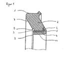
- FIG. 1 shows the section through a sealing body 1 according to the invention for a mechanical seal, comprising a trapezoidal sealing body 2, a stiffening ring 3 and a wave-shaped sealing profile.
- the stiffening ring 3 is made due to production L-shaped, while the short leg is directed radially outward.
- 1 notches 6 are embedded in the sealing body.
- the strain relief 8 is executed in this embodiment as an approximately circular undercut.
- a further sealing profile 4 is formed at the radially inner peripheral surface 9 of the sealing body 1.
- the surface is wave-shaped 10 and may also be conical depending on the sliding or counter ring.
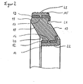
- FIG. 2 shows the section through a sealing body 11 for a mechanical seal, each with a stiffening ring 12, 13 on the radially inner 14 and the outer 15 peripheral surface.
- the stiffening rings 12, 13 have openings 16, 17, which may be contained in the stiffening rings 12, 13 in the form of regular or irregularly arranged holes.
- the stiffening rings 12, 13 are also made of perforated plates.
- strain reliefs 20, 21 are embedded in the axially outer surfaces 18, 19 of the sealing body 11 strain reliefs 20, 21 are embedded.
- wave-shaped sealing profiles 22, 23 are formed, which can also be conical.
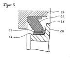
- FIG. 3 shows the section through a drive seal 24, which is mounted in a housing 26 by means of a trapezoidal sealing body 25.
- the sealing body 25 is fixed by means of a stiffening ring 29.
Landscapes
- Engineering & Computer Science (AREA)
- General Engineering & Computer Science (AREA)
- Mechanical Engineering (AREA)
- Mechanical Sealing (AREA)
Description
Die Erfindung beschreibt eine Gleitringdichtung, insbesondere Laufwerkdichtung, umfassend einen winkelförmigen Gleit- und Gegenring, die mit Ihren radialen Dichtschenkeln eine Dichtfläche bilden, und aus elastomerem Werkstoff bestehenden, trapezförmigen Dichtkörpern, die zwischen dem, die Gleitringdichtung aufnehmenden Gehäuse und der radial äußeren Oberfläche der axialen Schenkel des Gleit- und Gegenringes angeordnet sind, wobei die trapezförmigen Dichtkörper mit einem metallischen Versteifungsring ausgestattet sind und der Dichtkörper einen Versteifungsring besitzt, der in dem radial inneren Ende des trapezförmigen Dichtkörper angeordnet ist wobei die Verbindung zwischen Dichtkörper und radial äußerer Oberfläche der axialen Schenkel des Gleit- und Gegenringes als Preßsitz toleriert ist.The invention relates to a mechanical seal, in particular drive seal, comprising an angular sliding and counter ring, which form a sealing surface with their radial sealing legs, and made of elastomeric material, trapezoidal sealing bodies, between the, the mechanical seal receiving housing and the radially outer surface of the axial Legs of the sliding and counter-ring are arranged, wherein the trapezoidal sealing bodies are equipped with a metallic stiffening ring and the sealing body has a stiffening ring which is arranged in the radially inner end of the trapezoidal sealing body wherein the connection between the sealing body and the radially outer surface of the axial leg of the Sliding and counter ring is tolerated as a press fit.
Laufwerkdichtungen als spezielle Ausführung von Gleitringdichtungen kommen dann zum Einsatz wenn es betriebsbedingt zu starken Verschmutzungen an den Aggregaten, Maschinen oder Anlagen kommen kann.Drive seals as a special version of mechanical seals are used when there is a risk of heavy contamination on the units, machines or systems due to operational reasons.
Es ist allgemein bekannt, zwischen den radial äußeren Oberflächen der axialen Schenkel der Gleit- bzw. Gegenringe und dem die Laufwerkdichtung aufnehmenden Gehäuse Dichtungskörper aus elastischem Werkstoff, wie z. B. aus Gummi, vorzusehen, die außer der Funktion des Abdichtens auch gleichzeitig die Funktion der Drehmomentübertragung und der axialen Dichtpressung übernehmen.It is well known, between the radially outer surfaces of the axial legs of the sliding or counter-rings and the housing receiving the drive seal sealing body made of elastic material, such. As made of rubber, provide the same function as the torque transmission and the axial sealing pressure in addition to the function of sealing.
Die Drehmomente in einer gattungsgemäßen Laufwerkdichtung werden dabei von den Gleitflächen über die axialen Schenkel der Gleit- und Gegenringe und die Dichtkörper auf das Gehäuse übertragen. Damit die Drehmomente von den axialen Schenkeln der Gleit- und Gegenringe auf die Dichtkörper übertragen werden können, muß an dieser Verbindungsstelle eine ausreichende Haftreibung vorhanden sein. Dabei kann die Kraft, die von den Dichtkörpern auf die Gleit- und Gegenringe ausgeübt wird, u. a. über die Schrägstellung und die Abmaße der trapezförmigen Dichtkörper gesteuert werden.The torques in a generic drive seal are transmitted from the sliding surfaces on the axial legs of the sliding and counter-rings and the sealing body on the housing. So that the torques of the axial limbs of the sliding and counter rings can be transmitted to the sealing body, sufficient static friction must be present at this connection point. In this case, the force exerted by the sealing bodies on the sliding and counter rings, u. a. be controlled by the inclination and the dimensions of the trapezoidal sealing body.
Um einen gezielten Einfluß auf den Kraftfluß im Dichtkörper zu erlangen, wird in der DE OS 16 50 024 vorgeschlagen, einen metallischen Federungskörper in den Dichtkörper zu integrieren. Hierbei soll ein loser zwischen Gleitring und Maschinengehäuse einzulegender Dichtkörper geschaffen werden, der bei einfachster Gestaltung eine verhältnismäßig große Axialbewegung des Gleitringes zuläßt, ohne dabei den drehfesten Kontakt sowohl am Gleitringrücken als auch am Maschinengehäuse zu verlieren.
Durch eine solche Einbindung eines Federungskörpers wird erreicht, dass bei axialer Verschiebung des Gleitringes der Dichtkörper sowohl auf Druck als auch auf Biegung, im Gegensatz zur üblichen Schubbeanspruchung bei den bekannten Dichtkörpern, beansprucht wird.
Bei dieser Lösung wird zwar der Kraftfluß im Dichtkörper gezielt beeinflusst, ein Kippen des Dichtkörpers kann aber nicht verhindert werden. So dass es insbesondere am Gleitringrücken zu einer verminderten Auflage des Dichtkörpers und somit zu einer verminderten Haftreibung und zu niedrigeren übertragbaren Drehmomenten kommen kann. Gleichzeitig können, im Falle des Kippens des Dichtkörpers, Verunreinigungen und Schmiermittel unter den Dichtkörper gelangen, was zu einer dauerhaften Beeinträchtigung des Kraftflusses führen kann.In order to obtain a targeted influence on the power flow in the sealing body, 16 50 024 is proposed in DE OS to integrate a metallic suspension body in the sealing body. Here, a loose between sliding ring and machine housing einulegender sealing body to be created, which allows for the simplest design a relatively large axial movement of the slide ring, without losing the rotationally fixed contact on both Gleitringrücken and on the machine housing.
Such an integration of a suspension body ensures that, in the case of an axial displacement of the sliding ring, the sealing body is subjected both to pressure and to bending, in contrast to the usual shear stress in the known sealing bodies.
In this solution, although the power flow is specifically influenced in the sealing body, a tilting of the sealing body can not be prevented. So that it can come especially at the Gleitringrücken to a reduced support of the sealing body and thus to a reduced static friction and lower transferable torques. At the same time, in the case of tilting of the sealing body, impurities and lubricant can get under the sealing body, which can lead to a permanent impairment of the power flow.
In der US 3,279,804 wird vorgeschlagen, als Versteifungsringe metallische Stanzteile an das radial äußere Ende des Dichtkörpers anzubinden, so dass es zu einer starren Anbindung des Dichtkörpers an das Gehäuse kommt. Ein Kippen des Dichtkörpers am radial äußeren Ende wäre somit ausgeschlossen. Die Druckschrift offenbart weiterhin, die Anbindung eines S-förmig gebogenen Stanzteiles, an das radial äußere Ende des Dichtkörpers. Bei dieser Lösung steht lediglich ein Schenkel des Stanzteiles mit dem Gehäuse in Kontakt, der andere Schenkel ist vom Gehäuse beabstandet und mit einem elastomeren Werkstoff beaufschlagt, so dass es zu einer Abdichtung zwischen Stanzteil und Gehäuse kommt.
Eine Abdichtung ist hierbei aber nur bedingt möglich, da ein Schenkel des metallischen, kreisförmigen Stanzteiles unmittelbar mit dem Gehäuse in Verbindung steht, gibt das Stanzteil den Sitz des Dichtkörpers im Gehäuse vor. Um eine Dichtheit am Gehäuse durch den am anderen Schenkelende befindlichen elastomeren Werkstoff zu erlangen, muß dieser über das radial äußere Ende des Stanzteiles hinausragen. Da gummielastische Werkstoffe aber nahezu inkompressibel sind, wird der gummielastische Werkstoff bei der Montage aber so stark deformiert, dass er beschädigt oder sogar zerstört werden kann.
Da der gummielastische Werkstoff über den Versteifungsring hinausragt und der Versteifungsring nicht elastisch ist, kann es zu Schwierigkeiten beim Einfügen der Gleitringdichtung in das Gehäuse kommen. Der Einsatz von Montagehilfen oder Vorrichtungen ist dabei kostenintensiv und zeitaufwendig.
Ein weiterer Nachteil ist die starre Anbindung des Dichtkörpers an den Versteifungsring. Radiale und axiale Verschiebung der Gleitringe führen zu Zugspannungen, die an den axial äußeren Oberflächen der Dichtkörper am größten sind. Eine starre Anbindung an den Versteifungsring führt somit an den äußeren Oberflächen der Dichtkörper zu Spannungsspitzen, die zu einem Lösen der Verbindung zwischen Versteifungsring und Dichtkörper führen kann.It is proposed in US Pat. No. 3,279,804 to connect metallic stamped parts to the radially outer end of the sealing body as stiffening rings, so that a rigid connection of the sealing body to the housing occurs. Tilting of the sealing body at the radially outer end would thus be excluded. The publication further discloses the connection of an S-shaped bent punched part, to the radially outer end of the sealing body. In this solution, only one leg of the stamped part is in contact with the housing, the other leg is spaced from the housing and acted upon by an elastomeric material, so that there is a seal between the stamped part and the housing.
However, a seal is only conditionally possible because one leg of the metallic, circular stamped part is directly connected to the housing, the stamped part predetermines the seat of the sealing body in the housing. In order to gain a tightness on the housing through the located at the other end of the leg elastomeric material, this must protrude beyond the radially outer end of the stamped part. However, since rubber-elastic materials are almost incompressible, the rubber-elastic material is so strongly deformed during assembly that it can be damaged or even destroyed.
Since the rubber-elastic material protrudes beyond the stiffening ring and the stiffening ring is not elastic, there may be difficulties in inserting the mechanical seal in the housing. The use of assembly aids or devices is costly and time consuming.
Another disadvantage is the rigid connection of the sealing body to the stiffening ring. Radial and axial displacement of the slip rings lead to tensile stresses that are greatest at the axially outer surfaces of the sealing body. A rigid connection to the stiffening ring thus leads to the outer surfaces of the sealing body to voltage spikes, which can lead to a loosening of the connection between the stiffening ring and sealing body.
Die Anbindung des Dichtkörpers über einen Versteifungsring an das Gehäuse bedingt weiterhin, dass hier ein großes Drehmoment übertragen werden kann. Dies stellt in Bezug auf den Kraftfluß wiederum einen Nachteil dar, da die größten Umfangskräfte an der radial äußeren Oberfläche der Gleit- bzw. Gegenringe auftreten.
Aus der EP 0005159 A ist eine Gleitringdichtung zu entnehmen bei der ein Dichtkörper an seinem Innenumfang einen wellenförmigen Profilquerschnitt aufweist. Bei dieser Art von Gleitringdichtungen sind keine Zugbeanspruchungen gegeben, sodass auf eine Zugentlastung verzichtet werden kann.The connection of the sealing body via a stiffening ring to the housing further requires that a large torque can be transmitted here. This in turn represents a disadvantage in terms of the power flow, since the largest circumferential forces occur on the radially outer surface of the sliding or counter rings.
From EP 0005159 A, a mechanical seal can be seen in which a sealing body has on its inner circumference a wave-shaped profile cross-section. In this type of mechanical seals no tensile stresses are given, so that can be dispensed with a strain relief.
Es ist daher Aufgabe der Erfindung die oben genannten Nachteile zu überwinden und eine Gleitringdichtung zu entwickeln, die eine optimale Anbindung an den Gleitring und damit eine sichere Übertragung des Drehmoments gewährleistet und mit der die auftretenden Zugspannungen im trapezförmigen Dichtkörper gezielt beeinflusst werden können und die keinen zusätzlichen Bauraum benötigt.It is therefore an object of the invention to overcome the above-mentioned disadvantages and to develop a mechanical seal, which ensures an optimal connection to the seal ring and thus a safe transmission of torque and with the occurring tensile stresses in the trapezoidal sealing body can be specifically influenced and no additional Space required.
Diese Aufgabe wird erfindungsgemäß durch die Merkmale des Patentanspruchs 1 gelöst, vorteilhafte Weiterbildungen der Erfindung sind in den Unteransprüchen dokumentiert.This object is achieved by the features of
Durch die erfindungsgemäße Ausgestaltung des Dichtkörpers ist es nun möglich, eine optimale Anbindung des Dichtkörpers an den Gleitring und damit eine sichere Übertragung des Drehmomentes zu gewährleisten. Dabei bietet das wellenförmige, elastomere Dichtungsprofil einerseits die Möglichkeit einer leichten Montage und andererseits wird durch das Wellenprofil gewährleistet, dass der elastomere Werkstoff nicht überansprucht wird. Eine Überanspruchung kann nicht erfolgen, weil der überschüssige, elastomere Werkstoff bei der Montage in die Wellentäler ausweichen kann.Due to the inventive design of the sealing body, it is now possible to ensure an optimal connection of the sealing body to the sliding ring and thus a secure transmission of torque. The wavy, elastomeric sealing profile on the one hand offers the possibility of easy assembly and on the other hand is ensured by the wave profile that the elastomeric material is not overstretched. An over-claim can not be made because the excess, elastomeric material can dodge during assembly in the troughs.
Die Bemaßung zwischen der radial inneren Oberfläche des Dichtkörpers und der radial äußeren Oberfläche der Gleit- und Gegenringe ist als Presspassung ausgeführt. Es besteht daher keine lose Verbindung, sondern die Bauteile werden kraftschlüssig zusammengehalten. Somit stehen, neben der aus den Abmaßen und der Schrägstellung der Dichtkörper aufgebrachten Kräften, weitere Kräfte zu Verfügung, welche die Haftreibung erhöhen und die eine optimale Übertragung der Drehmomente unterstützen. So können selbst größte Drehmomente, wie sie z. B. bei einem Verkleben der Gleitflächen durch Schmutz oder Korrosion entstehen, übertragen werden.
Ein weiterer erfindungsgemäßer Vorteil ergibt sich durch die Presspassung dahingehend, dass die Bauteile während der Montage nicht auseinanderfallen können und dass kein Verschieben des Dichtkörpers, bei sich auf dem Gleitring aufbauendem Schmutz, erfolgen kann.The dimensioning between the radially inner surface of the sealing body and the radially outer surface of the sliding and counter rings is designed as a press fit. There is therefore no loose connection, but the components are held together positively. Thus, in addition to the applied from the dimensions and the inclination of the sealing body forces, other forces available, which increase the static friction and support an optimal transmission of torque. So even the largest torques, as z. B. when gluing the sliding surfaces caused by dirt or corrosion, are transmitted.
Another inventive advantage results from the interference fit to the effect that the components during assembly can not fall apart and that no displacement of the sealing body, can be done with auf constructing dirt on the slide ring.
Im Gegensatz zur radialen Höhe der trapezförmigen Dichtkörper ist die Höhe des elastomeren Dichtprofils gering und liegt im Bereich von etwa einem bis zu wenigen Millimetern. Durch die geringe Höhe des wellenförmigen Dichtungsprofils unterliegt der Dichtkörper auch nur einem geringen Setzen, was sich wiederum positiv auf das Wartungsverhalten und die Übertragung des Drehmomentes auswirkt.In contrast to the radial height of the trapezoidal sealing body, the height of the elastomeric sealing profile is low and is in the range of about one to a few millimeters. Due to the small height of the wave-shaped sealing profile of the sealing body is subject to only a small setting, which in turn has a positive effect on the maintenance behavior and the transmission of torque.
Durch die erfindungsgemäße Einbringung des Versteifungsringes in den Dichtkörper an der radial inneren Umfangsoberfläche des Dichtkörpers, ist ein Vertwisten des Dichtkörpers am Innenumfang nun nicht mehr möglich. Aus diesem Grund kann sich der Dichtkörper nicht vom Gleitring abheben und es können weder Verunreinigungen noch Schmierstoffe unter den Dichtkörper gelangen.Due to the inventive introduction of the stiffening ring in the sealing body on the radially inner peripheral surface of the sealing body, a Vertwisten the sealing body on the inner circumference is no longer possible. For this reason, the sealing body can not stand out from the sliding ring and it can get neither impurities nor lubricants under the sealing body.
Durch die axialen und radialen Bewegungen der Gleit- bzw. Gegenringe kommt es u. a. zu Zugspannungen in den Dichtkörpern. Diese Zugspannungen erreichen an den äußeren Oberflächen der Dichtkörper ihr Maximum. So dass die Verbindung zwischen Dichtkörper und Versteifungsring an diesen Stellen maximal belastet werden. Um diese Belastungen zu minimieren und/oder umzulenken wird in diesen Bereichen im Dichtkörper eine Zugentlastung ausgebildet. Die Zugentlastung wird in Form einer hohlkehlenförmigen Hinterschneidung unmittelbar im Anbindungsbereich zwischen elastomerem Werkstoff und Versteifungsring an den Dichtkörper angeformt.Due to the axial and radial movements of the sliding or counter rings, there are, among other things, tensile stresses in the sealing bodies. These tensile stresses reach the outer surfaces of the sealing body their maximum. So that the connection between the sealing body and stiffening ring are subjected to maximum load at these points. To minimize these loads and / or deflect a strain relief is formed in these areas in the sealing body. The strain relief is formed in the form of a groove-shaped undercut directly in the connection region between the elastomeric material and stiffening ring to the sealing body.
In einer weiteren Ausgestaltungsform der Erfindung wird vorgeschlagen, die äußeren Umfangsoberflächen der axialen Schenkel der Gleit- und Gegenringe leicht konisch auszuführen. Durch die leicht konische Ausbildung wird die Montage erleichtert, wobei die Verbindung aber stets als Preßsitz ausgeführt bleibt.
Der konischen Ausbildung der Gleit- und Gegenringe folgt der Dichtkörper dadurch, dass der elastomere Werkstoff, mit der wellenförmigen Profilierung, am inneren Umfang des Versteifungsringes ebenfalls konisch ausgebildet ist, so dass sich die Oberflächen der Bauteile beim Fügen stets parallel gegenüber stehen.In a further embodiment of the invention, it is proposed to make the outer circumferential surfaces of the axial limbs of the sliding and counter rings slightly conical. Due to the slightly conical design, the assembly is facilitated, but the connection always remains executed as a press fit.
The conical design of the sliding and counter rings follows the sealing body characterized in that the elastomeric material, with the wave-shaped profiling, also conical on the inner circumference of the stiffening ring, so that the surfaces of the components are always parallel when joining.
Je nach mechanischer Belastung der Gleitringdichtung kann es erforderlich sein, hohe Momente an das Gehäuse zu übertragen. Für diesen Fall wird in der Erfindung vorgeschlagen, einen weiteren Versteifungsring in den Dichtkörper zu integrieren. Dieser Versteifungsring wird erfindungsgemäß in das radial äußere Ende des Dichtkörpers eingebracht und besitzt ebenfalls, auf seiner dem Gehäuse zugewandten Seite, ein wellenförmiges Dichtungsprofil. Bezogen auf die Passungsmaße ist diese Verbindung auch als Presspassung ausgeführt. Wie an dem radial inneren Versteifungsring ist auch hier eine Zugentlastung in Form einer Hinterschneidung anformbar.Depending on the mechanical load of the mechanical seal, it may be necessary to transfer high torques to the housing. For this case, it is proposed in the invention to integrate a further stiffening ring in the sealing body. This stiffening ring is inventively introduced into the radially outer end of the sealing body and also has, on its side facing the housing, a wave-shaped sealing profile. Based on the fitting dimensions, this connection is also designed as a press fit. As on the radially inner reinforcing ring, a strain relief in the form of an undercut can also be formed here.
Fertigungsbedingt wird der Versteifungsring während des Formfüllens mehr oder weniger großen Drücken ausgesetzt. Gleichzeitig muß der flüssige, elastomere Werkstoff um den Versteifungsring herumfließen, was wiederum zur Deformation des Versteifungsringes führen könnte. Daher wird in der Erfindung vorgeschlagen, den Versteifungsring mit Öffnungen zu versehen, so dass der flüssige, elastomere Werkstoff während des Formfüllens durch den Versteifungsring fließen kann.For manufacturing reasons, the stiffening ring is exposed to more or less high pressures during mold filling. At the same time, the liquid, elastomeric material must flow around the stiffening ring, which in turn could lead to deformation of the stiffening ring. Therefore, it is proposed in the invention to provide the stiffening ring with openings, so that the liquid, elastomeric material can flow through the stiffening ring during mold filling.
Die erfindungsgemäße Integration eines Versteifungsringes in den Dichtkörper ist für die Art von Laufwerkdichtungen vorgesehen, bei denen baugrößenbedingt eine formschlüssige Drehmomentübertragung fertigungstechnisch nur aufwendig zu realisieren ist.The integration of a stiffening ring according to the invention into the sealing body is intended for the type of drive seals in which, due to the size of the construction, a form-fitting torque transmission can only be produced with great difficulty in terms of manufacturing technology.
Erfindungsgemäße Gestaltungsbeispiele einer Laufwerkdichtung sind nachstehend anhand von Zeichnungen und im weiteren in der Beschreibung näher erläutert. Es zeigen:
Figur 1 einen Schnitt durch ein erfindungsgemäßes Ausführungsbeispiel eines Dichtkörpers für eine Gleitringdichtung mit einem Versteifungsring, einer Zugentlastung und einem wellenförmigen Dichtungsprofil.Figur 2 einen Schnitt durch ein erfindungsgemäßes Ausführungsbeispiel eines Dichtkörpers für eine Gleitringdichtung mit jeweils einem Versteifungsring an der radial inneren und der äußeren Umfangsoberfläche, jeweils einer Zugentlastung und mit jeweils einem wellenförmigen Dichtungsprofil.Figur 3 einen Schnitt durch ein erfindungsgemäßes Ausführungsbeispiel einer Gleitring- bzw. Laufwerkdichtung im eingebauten Zustand.
- Figure 1 shows a section through an inventive embodiment of a sealing body for a mechanical seal with a stiffening ring, a strain relief and a wave-shaped sealing profile.
- Figure 2 shows a section through an inventive embodiment of a sealing body for a mechanical seal, each with a stiffening ring on the radially inner and outer peripheral surface, each a strain relief and each with a wave-shaped sealing profile.
- Figure 3 shows a section through an inventive embodiment of a Gleitring- or drive seal in the installed state.
Figur 1 zeigt den Schnitt durch einen erfindungsgemäßen Dichtkörper 1 für eine Gleitringdichtung, umfassend einen trapezförmigen Dichtkörper 2, einen Versteifungsring 3 und ein wellenförmiges Dichtungsprofil 4.
Der Versteifungsring 3 ist fertigungsbedingt L-förmig ausgeführt, dabei ist der kurze Schenkel nach radial außen gerichtet. Um den Versteifungsring 3 während des Forrnfüllens in seiner Position zu halten, sind in den Dichtkörper 1 Kerben 6 eingelassen.
Auf der axial äußeren Seite 7 des Dichtkörpers 1 ist eine Zugentlastung 8 angeformt. Die Zugentlastung 8 ist in diesem Ausführungsbeispiel als etwa kreisförmige Hinterschneidung ausgeführt.
An der radial inneren Umfangsoberfläche 9 des Dichtkörpers 1 ist ein weiteres Dichtungsprofil 4 angeformt. Die Oberfläche ist dabei wellenförmig 10 ausgebildet und kann je nach Gleit- bzw. Gegenring auch konisch ausgeführt sein.1 shows the section through a sealing
The
On the axially outer side 7 of the sealing
At the radially inner peripheral surface 9 of the sealing
In der Figur 2 ist der Schnitt durch einen Dichtkörper 11 für eine Gleitringdichtung mit jeweils einem Versteifungsring 12, 13 an der radial inneren 14 und der äußeren 15 Umfangsoberfläche dargestellt. Die Versteifungsringe 12, 13 besitzen Öffnungen 16, 17, die in Form von regelmäßigen oder unregelmäßig angeordneten Löchern in den Versteifungsringen 12, 13 enthalten sein können. Dabei können die Versteifungsringe 12, 13 auch aus Lochblechen gefertigt werden.
In die axial äußeren Oberflächen 18, 19 des Dichtkörpers 11 sind Zugentlastungen 20, 21 eingelassen. An die radialen Enden 14, 15 des Dichtkörpers 11 sind wellenförmige Dichtprofile 22, 23 angeformt, die auch konisch verlaufen können.2 shows the section through a sealing
In the axially
Figur 3 zeigt den Schnitt durch eine Laufwerkdichtung 24, die mittels eines trapezförmigen Dichtkörpers 25 in einem Gehäuse 26 montiert ist. Auf der radialen Oberfläche 27 des Gleit- bzw. Gegenringes 28 ist der Dichtkörper 25 mittels eines Versteifungsringes 29 fixiert.FIG. 3 shows the section through a drive seal 24, which is mounted in a
Claims (5)
- Mechanical seal, especially a mechanism seal (24), comprising an angular slide ring and interacting ring (28) which form a sealing face with their radial sealing legs, and trapezoid sealing bodies (1, 11, 25) which are formed from an elastomeric material and arranged between the housing (26) receiving the mechanical seal and the radially outer surface of the axial legs (27) of the slide ring and interacting ring, the trapezoid sealing bodies (1, 11, 25) being equipped with a metal reinforcing ring (3, 12, 13, 29) and the sealing body (1, 11, 25) having a reinforcing ring (3, 12, 29) which is arranged in the radially inner end of the trapezoid sealing body (1, 11, 25), the connection between the sealing body (1, 11, 25) and the radially outer surface of the axial legs (27) of the slide ring and interacting ring being tolerated as a press-fit, characterised in that an undulating, elastomeric profiled joint (4, 22, 23) is formed on the reinforcing ring (3, 12, 29) in the direction of the radially outer surfaces of the axial legs of the slide ring and interacting ring, and in that a strain relief (8, 20) in the form of an undercut, especially as a radius, is formed at the axially outer end (7) of the trapezoid sealing body (1, 11, 25) directly above the radially outer surface of the reinforcing ring (3, 12, 29).
- Mechanical seal according to claim 1, characterised in that the diameter of the radially outer surface of the axial legs of the slide ring and interacting ring tapers toward the axially outer end, such that a slightly conical connection is formed between the sealing body (1) and the slide ring or interacting ring.
- Mechanical seal according to one of claims 1 to 2, characterised in that in the radially outer end of the trapezoid sealing body (11), on the housing receiving the mechanical seal, is provided a further reinforcing ring (13), on the radially outer surface of which an undulating profiled joint (23) is provided, and in that the connection between the radially outer surface of the undulating profiled joint (23) and the housing is tolerated as a press-fit.
- Mechanical seal according to claim 3, characterised in that a strain relief (21), in the form of an undercut, especially as a radius, is formed at the axially inner end (19) of the trapezoid sealing body (11) directly below the radial end of the reinforcing ring (13).
- Mechanical seal according to one of claims 1 to 4, characterised in that apertures (16, 17) are provided in the reinforcing ring (3, 12, 13, 29), such that a connection is provided between the undulating profiled joint (4, 22, 23) and the trapezoid sealing body (1, 11, 25).
Applications Claiming Priority (2)
| Application Number | Priority Date | Filing Date | Title |
|---|---|---|---|
| DE2002116140 DE10216140B4 (en) | 2002-04-12 | 2002-04-12 | Mechanical seal with anti-rotation lock |
| DE10216140 | 2002-04-12 |
Publications (3)
| Publication Number | Publication Date |
|---|---|
| EP1353099A2 EP1353099A2 (en) | 2003-10-15 |
| EP1353099A3 EP1353099A3 (en) | 2004-02-04 |
| EP1353099B1 true EP1353099B1 (en) | 2006-07-05 |
Family
ID=28051269
Family Applications (1)
| Application Number | Title | Priority Date | Filing Date |
|---|---|---|---|
| EP20030007725 Expired - Lifetime EP1353099B1 (en) | 2002-04-12 | 2003-04-04 | Mechanical seal with anti-rotation feature |
Country Status (3)
| Country | Link |
|---|---|
| EP (1) | EP1353099B1 (en) |
| DE (2) | DE10216140B4 (en) |
| ES (1) | ES2268197T3 (en) |
Families Citing this family (2)
| Publication number | Priority date | Publication date | Assignee | Title |
|---|---|---|---|---|
| DE202006008635U1 (en) * | 2006-05-31 | 2006-08-03 | Burgmann Industries Gmbh & Co. Kg | Support ring for a sliding ring of a sliding ring sealing device used in sterile applications e.g. in medicine and in preparation of food comprises a carrier ring made from a material having a corrugated profile on its inner periphery |
| DE102011011475B4 (en) | 2011-02-17 | 2012-09-27 | Federal-Mogul Burscheid Gmbh | Mechanical seal |
Family Cites Families (11)
| Publication number | Priority date | Publication date | Assignee | Title |
|---|---|---|---|---|
| US3336660A (en) * | 1962-11-13 | 1967-08-22 | Federal Mogul Corp | Face seals |
| US3279804A (en) * | 1963-07-05 | 1966-10-18 | Chicago Rawhide Mfg Co | End face seal assembly |
| DE1650024A1 (en) * | 1967-11-16 | 1970-08-13 | Goetzewerke | Axial seal for rotating machine parts |
| DE6904242U (en) * | 1969-02-03 | 1969-04-30 | Goetze F Ag | SUPPORT RING FOR MECHANICAL SEALS |
| JPS589870B2 (en) * | 1975-08-30 | 1983-02-23 | エヌオーケー株式会社 | mechanical seal |
| EP0005159B1 (en) * | 1978-03-20 | 1981-07-08 | Goetze Ag | Slip-ring sealing |
| DE3412594C2 (en) * | 1984-04-04 | 1986-07-31 | Goetze Ag, 5093 Burscheid | Mechanical seal |
| DE3739514C2 (en) * | 1987-11-21 | 1995-07-13 | Kaco Gmbh Co | Sealing ring |
| GB9115991D0 (en) * | 1991-07-24 | 1991-09-11 | Crane John Uk Ltd | Mechanical face seals |
| DE4131472A1 (en) * | 1991-09-21 | 1993-03-25 | Schaeffler Waelzlager Kg | Elastomeric radial shaft sealing ring - has outer cylindrical sealing surface turned away from which is radial inner circular sealing lip |
| DE19955860B4 (en) * | 1999-11-20 | 2004-04-08 | Federal-Mogul Burscheid Gmbh | Mechanical seal |
-
2002
- 2002-04-12 DE DE2002116140 patent/DE10216140B4/en not_active Expired - Fee Related
-
2003
- 2003-04-04 DE DE50304111T patent/DE50304111D1/en not_active Expired - Lifetime
- 2003-04-04 EP EP20030007725 patent/EP1353099B1/en not_active Expired - Lifetime
- 2003-04-04 ES ES03007725T patent/ES2268197T3/en not_active Expired - Lifetime
Also Published As
| Publication number | Publication date |
|---|---|
| EP1353099A2 (en) | 2003-10-15 |
| DE10216140A1 (en) | 2003-11-06 |
| EP1353099A3 (en) | 2004-02-04 |
| DE50304111D1 (en) | 2006-08-17 |
| ES2268197T3 (en) | 2007-03-16 |
| DE10216140B4 (en) | 2004-07-08 |
Similar Documents
| Publication | Publication Date | Title |
|---|---|---|
| DE3320063C2 (en) | ||
| DE2004046C2 (en) | poetry | |
| EP2035732B1 (en) | Seal and seal arrangement | |
| DE3840691C2 (en) | Radial piston pump | |
| EP2529134A2 (en) | Rotary seal arrangement | |
| EP1995088B1 (en) | Insert mount component, elastic insert mount and strut support device | |
| DE2654738A1 (en) | LUBRICANT SEAL | |
| EP0050213B1 (en) | Self-aligning bearing | |
| EP2459906A1 (en) | Seal and seal arrangement | |
| DE102007049704A1 (en) | Internal gear pump for a brake system | |
| DE3517959C2 (en) | ||
| EP0493731B1 (en) | Flexible bearing | |
| EP3872373B1 (en) | Seal ring and its use | |
| DE2726033C2 (en) | Seal, especially for chain pins on crawler tractors or similar. | |
| DE10104788C2 (en) | Mechanical seal with radial anti-rotation lock | |
| DE10113442C2 (en) | Bearing arrangement for a shaft bearing | |
| WO2015022144A1 (en) | Sealing ring | |
| WO2010009799A1 (en) | Centrifugal pump | |
| EP1353099B1 (en) | Mechanical seal with anti-rotation feature | |
| DE102014219859A1 (en) | Universal joint | |
| EP0656462B1 (en) | Sealing device | |
| EP2093451B1 (en) | Brake power transfer assembly | |
| WO2014108122A1 (en) | Seal for a hydraulic piston-cylinder arrangement | |
| EP0116721A1 (en) | Shaft seal | |
| DE10237966B4 (en) | Hydro bearing with elastomer spring |
Legal Events
| Date | Code | Title | Description |
|---|---|---|---|
| PUAI | Public reference made under article 153(3) epc to a published international application that has entered the european phase |
Free format text: ORIGINAL CODE: 0009012 |
|
| AK | Designated contracting states |
Kind code of ref document: A2 Designated state(s): AT BE BG CH CY CZ DE DK EE ES FI FR GB GR HU IE IT LI LU MC NL PT RO SE SI SK TR |
|
| AX | Request for extension of the european patent |
Extension state: AL LT LV MK |
|
| PUAL | Search report despatched |
Free format text: ORIGINAL CODE: 0009013 |
|
| AK | Designated contracting states |
Kind code of ref document: A3 Designated state(s): AT BE BG CH CY CZ DE DK EE ES FI FR GB GR HU IE IT LI LU MC NL PT RO SE SI SK TR |
|
| AX | Request for extension of the european patent |
Extension state: AL LT LV MK |
|
| 17P | Request for examination filed |
Effective date: 20040722 |
|
| AKX | Designation fees paid |
Designated state(s): DE ES FR GB IT |
|
| 17Q | First examination report despatched |
Effective date: 20040917 |
|
| GRAP | Despatch of communication of intention to grant a patent |
Free format text: ORIGINAL CODE: EPIDOSNIGR1 |
|
| GRAS | Grant fee paid |
Free format text: ORIGINAL CODE: EPIDOSNIGR3 |
|
| GRAA | (expected) grant |
Free format text: ORIGINAL CODE: 0009210 |
|
| AK | Designated contracting states |
Kind code of ref document: B1 Designated state(s): DE ES FR GB IT |
|
| PG25 | Lapsed in a contracting state [announced via postgrant information from national office to epo] |
Ref country code: IT Free format text: LAPSE BECAUSE OF FAILURE TO SUBMIT A TRANSLATION OF THE DESCRIPTION OR TO PAY THE FEE WITHIN THE PRESCRIBED TIME-LIMIT;WARNING: LAPSES OF ITALIAN PATENTS WITH EFFECTIVE DATE BEFORE 2007 MAY HAVE OCCURRED AT ANY TIME BEFORE 2007. THE CORRECT EFFECTIVE DATE MAY BE DIFFERENT FROM THE ONE RECORDED. Effective date: 20060705 |
|
| REG | Reference to a national code |
Ref country code: GB Ref legal event code: FG4D Free format text: NOT ENGLISH |
|
| GBT | Gb: translation of ep patent filed (gb section 77(6)(a)/1977) |
Effective date: 20060721 |
|
| REF | Corresponds to: |
Ref document number: 50304111 Country of ref document: DE Date of ref document: 20060817 Kind code of ref document: P |
|
| ET | Fr: translation filed | ||
| REG | Reference to a national code |
Ref country code: ES Ref legal event code: FG2A Ref document number: 2268197 Country of ref document: ES Kind code of ref document: T3 |
|
| PLBE | No opposition filed within time limit |
Free format text: ORIGINAL CODE: 0009261 |
|
| STAA | Information on the status of an ep patent application or granted ep patent |
Free format text: STATUS: NO OPPOSITION FILED WITHIN TIME LIMIT |
|
| 26N | No opposition filed |
Effective date: 20070410 |
|
| PGFP | Annual fee paid to national office [announced via postgrant information from national office to epo] |
Ref country code: FR Payment date: 20110331 Year of fee payment: 9 |
|
| PGFP | Annual fee paid to national office [announced via postgrant information from national office to epo] |
Ref country code: DE Payment date: 20110429 Year of fee payment: 9 Ref country code: ES Payment date: 20110425 Year of fee payment: 9 Ref country code: GB Payment date: 20110328 Year of fee payment: 9 |
|
| PGFP | Annual fee paid to national office [announced via postgrant information from national office to epo] |
Ref country code: IT Payment date: 20110416 Year of fee payment: 9 |
|
| GBPC | Gb: european patent ceased through non-payment of renewal fee |
Effective date: 20120404 |
|
| REG | Reference to a national code |
Ref country code: FR Ref legal event code: ST Effective date: 20121228 |
|
| PG25 | Lapsed in a contracting state [announced via postgrant information from national office to epo] |
Ref country code: GB Free format text: LAPSE BECAUSE OF NON-PAYMENT OF DUE FEES Effective date: 20120404 |
|
| REG | Reference to a national code |
Ref country code: DE Ref legal event code: R119 Ref document number: 50304111 Country of ref document: DE Effective date: 20121101 |
|
| PG25 | Lapsed in a contracting state [announced via postgrant information from national office to epo] |
Ref country code: IT Free format text: LAPSE BECAUSE OF NON-PAYMENT OF DUE FEES Effective date: 20120404 Ref country code: FR Free format text: LAPSE BECAUSE OF NON-PAYMENT OF DUE FEES Effective date: 20120430 |
|
| REG | Reference to a national code |
Ref country code: ES Ref legal event code: FD2A Effective date: 20130715 |
|
| PG25 | Lapsed in a contracting state [announced via postgrant information from national office to epo] |
Ref country code: ES Free format text: LAPSE BECAUSE OF NON-PAYMENT OF DUE FEES Effective date: 20120405 |
|
| PG25 | Lapsed in a contracting state [announced via postgrant information from national office to epo] |
Ref country code: DE Free format text: LAPSE BECAUSE OF NON-PAYMENT OF DUE FEES Effective date: 20121101 |