EP1353064A2 - Combustion stabilizing device - Google Patents
Combustion stabilizing device Download PDFInfo
- Publication number
- EP1353064A2 EP1353064A2 EP03007489A EP03007489A EP1353064A2 EP 1353064 A2 EP1353064 A2 EP 1353064A2 EP 03007489 A EP03007489 A EP 03007489A EP 03007489 A EP03007489 A EP 03007489A EP 1353064 A2 EP1353064 A2 EP 1353064A2
- Authority
- EP
- European Patent Office
- Prior art keywords
- heater
- fuel
- stabilizing device
- internal combustion
- combustion engine
- Prior art date
- Legal status (The legal status is an assumption and is not a legal conclusion. Google has not performed a legal analysis and makes no representation as to the accuracy of the status listed.)
- Withdrawn
Links
Images


Classifications
-
- F—MECHANICAL ENGINEERING; LIGHTING; HEATING; WEAPONS; BLASTING
- F02—COMBUSTION ENGINES; HOT-GAS OR COMBUSTION-PRODUCT ENGINE PLANTS
- F02M—SUPPLYING COMBUSTION ENGINES IN GENERAL WITH COMBUSTIBLE MIXTURES OR CONSTITUENTS THEREOF
- F02M69/00—Low-pressure fuel-injection apparatus ; Apparatus with both continuous and intermittent injection; Apparatus injecting different types of fuel
- F02M69/30—Low-pressure fuel-injection apparatus ; Apparatus with both continuous and intermittent injection; Apparatus injecting different types of fuel characterised by means for facilitating the starting-up or idling of engines or by means for enriching fuel charge, e.g. below operational temperatures or upon high power demand of engines
- F02M69/32—Low-pressure fuel-injection apparatus ; Apparatus with both continuous and intermittent injection; Apparatus injecting different types of fuel characterised by means for facilitating the starting-up or idling of engines or by means for enriching fuel charge, e.g. below operational temperatures or upon high power demand of engines with an air by-pass around the air throttle valve or with an auxiliary air passage, e.g. with a variably controlled valve therein
- F02M69/325—Low-pressure fuel-injection apparatus ; Apparatus with both continuous and intermittent injection; Apparatus injecting different types of fuel characterised by means for facilitating the starting-up or idling of engines or by means for enriching fuel charge, e.g. below operational temperatures or upon high power demand of engines with an air by-pass around the air throttle valve or with an auxiliary air passage, e.g. with a variably controlled valve therein with an auxiliary injection nozzle therein
-
- F—MECHANICAL ENGINEERING; LIGHTING; HEATING; WEAPONS; BLASTING
- F02—COMBUSTION ENGINES; HOT-GAS OR COMBUSTION-PRODUCT ENGINE PLANTS
- F02M—SUPPLYING COMBUSTION ENGINES IN GENERAL WITH COMBUSTIBLE MIXTURES OR CONSTITUENTS THEREOF
- F02M53/00—Fuel-injection apparatus characterised by having heating, cooling or thermally-insulating means
- F02M53/04—Injectors with heating, cooling, or thermally-insulating means
- F02M53/06—Injectors with heating, cooling, or thermally-insulating means with fuel-heating means, e.g. for vaporising
Definitions
- the present invention relates to a combustion stabilizing device which helps vaporize a fuel supplied to an automobile internal combustion engine.
- Conventional combustion stabilizing devices include, for example, a fuel injection valve, a heater, and an idle speed control valve (hereinafter referred to as "ISC valve") as described in U. S. Patent 5,482,023.
- ISC valve idle speed control valve
- Such a fuel control system mixes a part of air from the ISC valve (first air flow) with a fuel from the fuel injection valve.
- a passage for the air from the I SC valve has an annular opening around the outlet of the fuel injection valve to mix the air and fuel.
- the fuel from the fuel injection valve and the first air flow go into a cylindrical heater aligned downstream of the fuel injection valve.
- the heater has an air passage to receive another part of the air from the ISC valve.
- the air flowing through this air passage mixes, at the heater outlet, with the fuel spray flowing through the heater. Flowing through the heater helps vaporize the fuel from the fuel injection valve. Mixing at the heater outlet the fuel and the second air flow further helps vaporize the fuel.
- conventional combustion stabilizing systems have a line of, from upstream to downstream, the fuel injection valve, a combining point where the fuel from the fuel injection valve mixes with the first air flow, and a mixing chamber in the heater where the fuel mixes with the second airflow.
- the conventional systems send the vaporized fuel directly from the heater outlet into the main air passage.
- the combustion stabilizing device can help quickly start the internal combustion engine, clean up the exhaust gas, and particularly reduce the HC, by effectively helping atomize the fuel spray injected from the fuel injection valve and reduce adhesion on an intake pipe inside. Atomizing fuel spray can also stabilize the combustion.
- PTC heater electrical heater
- combustion stabilizing systems can effectively clean up the exhaust gas in starting up the engine but cannot operate continuously during normal driving. It is thus difficult from the point of cost performance that the combustion stabilizing systems can become widely available for the internal combustion engines.
- the object of the present invention is to provide a combustion stabilizing system which can continuously operate and supply a vaporized fuel during driving. This can reduce harmful substances produced during driving and clean the exhaust gas more effectively.
- the second heater may transfer heat to the first heater so that the second heater also vaporizes the fuel.
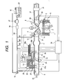
- Fig. 1 is a system configuration of an internal combustion engine using the combustion stabilizing device according to the first embodiment of the present invention.
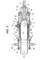
- Fig. 2 is across sectional view of the combustion stabilizing device according to the first embodiment of the present invention.
- Fig. 3 is a perspective view of the combustion stabilizing device according to the first embodiment of the present invention.
- the internal combustion engine 1 is a well known ignition internal combustion engine which uses a fuel of gasoline and has a plurality of cylinders, although only one cylinder is shown in Fig. 1.
- the internal combustion engine 1 includes an intake valve 4 for taking air and mixed air into a combustion chamber 2 , and an exhaust valve 5 for exhausting gas after combustion.
- the combustion chamber 2 has an ignition plug 3.
- the internal combustion engine 1 includes a water temperature sensor 7 on the side of the ignition chamber 2 for detecting the temperature of an engine coolant 6, and a rotation sensor (not shown) for detecting the rotation number of the engine. Both sensors serve to detect the operating condition of the internal combustion engine 1.
- An intake system for taking air into the combustion chamber 2 includes a mass air flow sensor 8 for measuring the intake air passing through an air cleaner (not shown), an electronic throttle valve 10 for electrically controlling the amount of the intake air, which can open/close and is connected to a rotating shaft which rotates in response to the driver's foot pressure on the gas pedal or to the operating condition of the internal combustion engine, a throttle positioning sensor 28 , an intake manifold 11, a intake manifold branch pipe 31 which branches from the intake manifold 11 to each cylinder of the internal combustion engine 1, and intake port 14 having the intake valve 4.
- a controller 34 receives flow rate data of the intake air 26 from the air flow sensor 8 and opening data of a valve 29 of the electronic throttle valve 10 from the throttle positioning sensor 28. The controller 34 use those date to detect and control the operating condition of the internal combustion engine 1.
- the fuel injection system includes two types of fuel injection valves, i.e., a plurality of first fuel injection valves 12 and a single second fuel injection valve 13.
- the first fuel injection valve 12 connects to the intake port 14 to inject, downstream of the intake manifold 11, the fuel toward the intake valve 4 of each cylinder.
- the second fuel injection valve 13 connects to the combustion stabilizing device 27.
- a fuel supply system includes a fuel tank 16 containing a fuel 24, a fuel pump 17 delivering the fuel 24 from the fuel tank 16, a fuel filter 18, a pressure regulator 19 for regulating the pressure of the delivered fuel 24 at a predetermined value, the first fuel injection valve 12 for injecting the fuel into the intake port 14 of each cylinder (#1, #2, #3, ...), and the second fuel injection valve 13 supplying the fuel downstream of the throttle valve 29. All of those components connect to each other via a fuel pipe 35.
- An exhaust system includes an exhaust port 36 having the exhaust valve 5 for each cylinder, an exhaust manifold 37, an oxygen concentration sensor 20 for measuring oxygen concentration in the exhaust gas, a three way catalytic converter 21 for cleaning the exhaust gas, and a dissipative muffler (not shown).
- the controller 34 receives the oxygen concentration data from the oxygen concentration sensor 20 to use them to detect and control the operation condition of the internal combustion engine 1.
- the three way catalytic converter 21 can clean the NOx, CO, and HC at a high cleanup rate at the same time which are exhausted from the internal combustion engine 1 operated nearly at a theoretical air-fuel ratio.
- the combustion stabilizing device 27 connects to the branched passage 15 opened downstream of the electronic throttle valve 10.
- bypass manifolds 22, 23 branch from the intake pipe 9 to bypass the electronic throttle valve 10 from upstream to downstream
- the bypass manifold 22 can pass carrier air 22a which carries the fuel 24 injected from the second fuel injection valve 13.
- An idle speed control valve 25 on the bypass manifold 22 controls the air flow rate through the bypass manifold 22.
- the bypass manifold 23 can pass air-assist air 23a which helps atomize the fuel 24 injected from the second fuel injection valve 13.
- the branch passage 15 emits the vaporizing fuel 30.
- the combustion chamber 2 receives a mixed gas of the intake air 26 and the fuel 24 injected from the fuel injection valves 12 and 13.
- the received mixed gas is compressed and ignited by the spark plug 3 to start the combustion.
- the exhaust gas from the internal combustion engine 1 will escape into the atmosphere through the exhaust system.
- the combustion stabilizing device 27 includes a body 39 and a heater body 40.
- the body 39 is primarily provided with a second fuel injection valve 13 and a carrier air feed pipe 37.
- the bypass manifold 22 connects to the carrier air feed pipe 37 and will send the carrier air 22a shown in Fig. 1 through the pipe 37.
- the fuel pipe 37 and a fuel pipe holding member 36 fasten the fuel injection valve 13 on the body 39.
- the fuel injection valve 13 receives the fuel 24 through the fuel pipe 35 delivered by the fuel pump 17 from the fuel tank 16 shown in Fig. 1.
- the heater body 40 has a first heater and a second heater as described hereinafter.
- the first heater is the same as the conventional ones.
- the second heater is an additional one according to the present embodiment.
- the heater body 40 has a positive electrode 48 and a negative electrode (body earth) to power the first heater.
- the second heater is provided on the outside of the heater body 40 and receives the engine coolant 6 shown in Fig. 1.
- the fuel vaporizes in the heater body 40 and leaves the combustion stabilizing device 27 as the vaporizing fuel 30.
- the first heater in the heater body 40 includes a plate-like heater 50 around the outside of a sub passage heat transfer tube 55.
- the heater 50 is a ceramic heater and has upper and lower plane electrodes which heat up when current passes through them.
- the heater 50 of a heating element uses a PTC (Positive Temperature Coefficient Thermistor) heater which, at temperatures greater than or equal to a predetermined value, can rapidly increase its resistance to decrease the current through it and keep its temperature constant.
- PTC Physical Temperature Coefficient Thermistor
- PTC heater 50 fastens against the positive electrode 54 and the heat transfer tube 55 which forms the negative electrode and a sub passage.
- a heater guide 47 holds the positive electrode plate 54 such that a rubber elastic body 49 always presses the electrode plate 54 against the PTC heater 50.
- the positive electrode plate 54 connects via a ring electrode 44 to the positive electrode terminal 48 outside the heater body 40.
- the electrically conductive heat transfer tube 55 presses on the metal heater body 40.
- the insulating heater guide 47 and insulating cover 51 isolate the electrodes 54, 48. When current passes through the electrode 48 and heater body 40, the heater 50 heats up to heat the transfer tube 55.
- Seal rings 41, 42, and O-ring 43 seal the sub passage heat transfer tube 55 from the internal passage.
- a mixer 43 and the body 39 press the seal ring 42 and O-ring 43 to seal these rings.
- the mixer 45 is positioned such that O-rings 43, 44 can seal the internal passage.
- the second heater introduces the coolant 6 into a hot water passage enclosed with a cover that forms hot water pipes 38a and 38b around the outside of the heater body 40 and that presses a seal ring 56.
- the hot water pipes 38a, 38b connect to piping for the engine coolant 6 shown in Fig. 1.
- the temperature of the coolant raises to, for example, 80 °C.
- the second heater uses the warmed coolant as a heat source to help vaporize the fuel sprayed from the fuel injection valve 13.
- the second heater needs no electricity or power unlike the PTC heater in the first heater so that the second heater can operate continuously during driving.
- the first heater when the engine starts up and before it warms up, can vaporize the fuel injected from the second fuel injection valve 13 and send it through the biased passage 15 as the vaporizing fuel 30 into the intake manifold 11.
- the engine coolant 6 After the engine warms up, the engine coolant 6 always heats the heater body 40 to about 80 °C.
- the second heater can vaporize the fuel and send it through the biased passage 15 as the vaporizing fuel 30 into the intake manifold 11.
- the second heater body 60 is in contact with the heat transfer tube 55 of the first heater so that the heat can conduct from the body 60 to the heat transfer tube 55.
- the second heater can always preheat the first heater to reduce the inrush current at turn-on.
- the second heater can vaporize the fuel from the second fuel injection valve 13without powering the first heater.
- the first heater helps vaporize the sprayed fuel when the engine starts up, while the second heater helps vaporize the sprayed fuel after the engine warms up.
- the combustion stabilizing system can continuously operate and supply a vaporized fuel during driving and reduce harmful substances produced during driving and clean the exhaust gas more effectively.
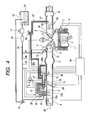
- Fig. 4 is a system configuration of an internal combustion engine using the combustion stabilizing device according to the second embodiment of the present invention.
- Fig. 5 is across sectional view of the combustion stabilizing device according to the second embodiment of the present invention.
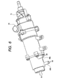
- Fig. 6 is a perspective view of the combustion stabilizing device according to the second embodiment of the present invention.
- Fig. 7 is a cross sectional view along the line A-A of Fig. 5. The same numbers refer to the same elements of Figs. 1 to 3.
- FIG. 4 the whole configuration of an internal combustion engine using the combustion stabilizing device according to the present embodiment will be described Most of the configuration is similar to that shown in Fig. 1 so that the difference from the first embodiment in Fig. 1 will primarily be described.
- the internal combustion engine with an exhaust recycling system includes an exhaust recycling passage 67 for recycling the exhaust gas from the exhaust pipe 37 to the intake pipe 31.
- An exhaust recycling control valve 66 controls the flow rate of the recycled exhaust gas 69.
- a pipe 68a downstream of the exhaust recycling control valve 66 connects to the second heater of the combustion stabilizing device 27 and sends a hot exhaust gas into the second heater.
- the exhaust recycling control valve 66 opens, negative pressure in the intake manifold 11 sucks the recycled exhaust gas 69 through the exhaust pipe 37 into the second heater body 60 shown in Fig. 5.
- the second heater uses as a heat source the exhaust gas which enters the heater.
- the exhaust gas which enters the heater then goes through a pipe 68b into the intake manifold 11, completing the original exhaust gas recycling.
- the second heater receives the recycled exhaust gas and uses it as a heat source to help vaporize the fuel.
- the second heater body 60 has pipes 68a and 68b, the axes of which do not intersect with the center axis of the second heater body 60.
- the recycled exhaust gas 69 flows around circumferentially as indicated by the open arrows in Fig. 7 so that the heat can conduct uniformly inside the second heater body 60.
- the second heater body 60 is in contact with the heat transfer tube 55 of the first heater so that the heat can conduct from the body 60 to the heat transfer tube 55.
- the second heater can always preheat the first heater to reduce the inrush current at turn-on.
- the second heater can vaporize the fuel from the second fuel injection valve 13 without powering the first heater.
- the heat source for the second heater is the coolant in the first embodiment and the exhaust gas in the second embodiment.
- Other heat sources such as engine oil heated after the warm-up, however, can be introduced into the second heater.
- the first heater helps vaporize the sprayed fuel when the engine starts up
- the second heater helps vaporize the sprayed fuel after the engine warms up.
- the combustion stabilizing system can continuously operate and supply a vaporized fuel during driving and can reduce harmful substances produced during driving and clean the exhaust gas more effectively.
- the system configuration of an internal combustion engine using the combustion stabilizing device according to the present embodiment is the same as that in Fig. 1.
- the cross sectional view of the combustion stabilizing device according to the present embodiment is the same as that in Fig. 2.
- the present embodiment has a different configuration of the second heater, which will be described below referring to Fig. 8.
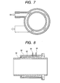
- Fig. 8 is a cross sectional view of a relevant part of the combustion stabilizing device according to the third embodiment of the present invention.
- the same numbers refer to the same elements of Fig. 5.
- the second heater winds a coiled copper wire 63 around the metal second heater body 60 which forms the heat transfer tube for the fuel vaporization.
- Plastic resin 62 covers the outside of the wire 63 to thermally insulate it.
- the copper wire 63 with voltage applied across the ends 64, 65 will heat up.
- the heated copper wire will increase its resistance to reduce the current through it.
- the generated heat will conduct outside of the coil to reduce the coil temperature.
- the constant voltage applied across the ends 64, 65 of the copper wire 63 allows the second heater to keep a constant temperature at which the heating balances with the heat conduction.
- the second heater using the copper wire 63 can heat up less quickly than the first heater using the PTC heater.
- the second heater can keep the heater temperature constant with less power consumption than the first heater using the PTC heater.
- the second heater body 60 is in contact with the heat transfer tube 55 of the first heater so that the heat can conduct from the body 60 to the heat transfer tube 55.
- the second heater can always preheat the first heater to reduce the inrush current at turn-on. Additionally, after the engine warms up, the second heater can vaporize the fuel from the second fuel injection valve 13without powering the first heater.
- the first heater helps vaporize the sprayed fuel when the engine starts up
- the second heater helps vaporize the sprayed fuel after the engine warms up.
- the combustion stabilizing system can continuously operate and supply a vaporized fuel during driving and can reduce harmful substances produced during driving and clean the exhaust gas more effectively.
- the present invention can provide a combustion stabilizing system which can continuously operate and supply a vaporized fuel during driving.
Landscapes
- Engineering & Computer Science (AREA)
- Chemical & Material Sciences (AREA)
- Combustion & Propulsion (AREA)
- Mechanical Engineering (AREA)
- General Engineering & Computer Science (AREA)
- Fuel-Injection Apparatus (AREA)
Abstract
Description
- The present invention relates to a combustion stabilizing device which helps vaporize a fuel supplied to an automobile internal combustion engine.
- Conventional combustion stabilizing devices include, for example, a fuel injection valve, a heater, and an idle speed control valve (hereinafter referred to as "ISC valve") as described in U. S. Patent 5,482,023. Such a fuel control system mixes a part of air from the ISC valve (first air flow) with a fuel from the fuel injection valve. A passage for the air from the I SC valve has an annular opening around the outlet of the fuel injection valve to mix the air and fuel. Right after mixing, the fuel from the fuel injection valve and the first air flow go into a cylindrical heater aligned downstream of the fuel injection valve. The heater has an air passage to receive another part of the air from the ISC valve. The air flowing through this air passage (second air flow) mixes, at the heater outlet, with the fuel spray flowing through the heater. Flowing through the heater helps vaporize the fuel from the fuel injection valve. Mixing at the heater outlet the fuel and the second air flow further helps vaporize the fuel.
- Thus, conventional combustion stabilizing systems have a line of, from upstream to downstream, the fuel injection valve, a combining point where the fuel from the fuel injection valve mixes with the first air flow, and a mixing chamber in the heater where the fuel mixes with the second airflow. The conventional systems send the vaporized fuel directly from the heater outlet into the main air passage.
- The combustion stabilizing device can help quickly start the internal combustion engine, clean up the exhaust gas, and particularly reduce the HC, by effectively helping atomize the fuel spray injected from the fuel injection valve and reduce adhesion on an intake pipe inside. Atomizing fuel spray can also stabilize the combustion.
- Conventional combustion stabilizing systems use an electrical heater (PTC heater) to vaporize the fuel when it contacts with the heater's inside, so that they need much power for the heater to fully vaporize the fuel and can only operate when the engine starts and for some minutes after starting.
- Conventional combustion stabilizing systems can effectively clean up the exhaust gas in starting up the engine but cannot operate continuously during normal driving. It is thus difficult from the point of cost performance that the combustion stabilizing systems can become widely available for the internal combustion engines.
- The object of the present invention is to provide a combustion stabilizing system which can continuously operate and supply a vaporized fuel during driving. This can reduce harmful substances produced during driving and clean the exhaust gas more effectively.
- (1) To achieve the above mentioned object, the present invention provides a combustion stabilizing device which may include a fuel injection valve, and a first heater for heating a fuel sprayed from the fuel injection valve. The device may further comprise a second heater for heating the fuel sprayed from the fuel injection valve, wherein the second heater may use a heat source different from the heat source for the first heater.Such a combustion stabilizing device can continuously operate and supply a vaporized fuel during driving.
- (2) In the combustion stabilizing device according to the present invention, the first heater can be an electric heater. The second heater may use as a heat source heat generated from the internal combustion engine.The first heater may vaporize the fuel in starting the internal combustion engine.The second heater may vaporize the fuel after warming up the internal combustion engine.
- (3) In the combustion stabilizing device according to the present invention, the second heater may use as a heat source a coolant for the internal combustion engine.
- (4) In the combustion stabilizing device according to the present invention, the second heater may use as a heat source an exhaust gas from the internal combustion engine.
- (5) In the combustion stabilizing device according to the present invention, the second heater can have a heat source inlet and/or a heat source outlet at either end of a cylindrical heater passage. The inlet and outlet can be positioned above and below the center axis of the heater passage such that the heat source turns around the heater passage.
- (6) In the combustion stabilizing device according to the present invention, the first heater can be a PTC heater. The second heater can be a coiled copper wire heating element.The first heater may vaporize the fuel in starting the internal combustion engine.The second heater may vaporize the fuel after warming up the internal combustion engine.
- (7) In the combustion stabilizing device according to the present invention, the second heater can be in contact with the first heater.
-
- After warming up the internal combustion engine, the second heater may transfer heat to the first heater so that the second heater also vaporizes the fuel.
-
- Figure 1 shows a system configuration of an internal combustion engine using the combustion stabilizing device according to the first embodiment of the present invention.
- Figure 2 shows a cross sectional view of the combustion stabilizing device according to the first embodiment of the present invention.
- Figure 3 shows a perspective view of the combustion stabilizing device according to the first embodiment of the present invention.
- Figure 4 shows a system configuration of an internal combustion engine using the combustion stabilizing device according to the second embodiment of the present invention.
- Figure 5 shows a cross sectional view of the combustion stabilizing device according to the second embodiment of the present invention.
- Figure 6 shows a perspective view of the combustion stabilizing device according to the second embodiment of the present invention.
- Figure 7 shows a cross sectional view along the line A-A of Figure 5.
- Figure 8 shows a cross sectional view of a relevant part of the combustion stabilizing device according to the third embodiment of the present invention.
-
- Referring to Figs. 1 to 3, the combustion stabilizing device according to the first embodiment of the present invention will be described below.
- Fig. 1 is a system configuration of an internal combustion engine using the combustion stabilizing device according to the first embodiment of the present invention. Fig. 2 is across sectional view of the combustion stabilizing device according to the first embodiment of the present invention. Fig. 3 is a perspective view of the combustion stabilizing device according to the first embodiment of the present invention.
- Referring to Fig. 1, an internal combustion engine using the combustion stabilizing device according to the present embodiment will be described. In Fig. 1, the
internal combustion engine 1 is a well known ignition internal combustion engine which uses a fuel of gasoline and has a plurality of cylinders, although only one cylinder is shown in Fig. 1. - The
internal combustion engine 1 includes an intake valve 4 for taking air and mixed air into acombustion chamber 2 , and anexhaust valve 5 for exhausting gas after combustion. Thecombustion chamber 2 has anignition plug 3. Theinternal combustion engine 1 includes a water temperature sensor 7 on the side of theignition chamber 2 for detecting the temperature of anengine coolant 6, and a rotation sensor (not shown) for detecting the rotation number of the engine. Both sensors serve to detect the operating condition of theinternal combustion engine 1. - An intake system for taking air into the
combustion chamber 2 includes a massair flow sensor 8 for measuring the intake air passing through an air cleaner (not shown), anelectronic throttle valve 10 for electrically controlling the amount of the intake air, which can open/close and is connected to a rotating shaft which rotates in response to the driver's foot pressure on the gas pedal or to the operating condition of the internal combustion engine, athrottle positioning sensor 28 , anintake manifold 11, a intakemanifold branch pipe 31 which branches from theintake manifold 11 to each cylinder of theinternal combustion engine 1, andintake port 14 having the intake valve 4. - A
controller 34 receives flow rate data of theintake air 26 from theair flow sensor 8 and opening data of avalve 29 of theelectronic throttle valve 10 from thethrottle positioning sensor 28. Thecontroller 34 use those date to detect and control the operating condition of theinternal combustion engine 1. - In the present embodiment, the fuel injection system includes two types of fuel injection valves, i.e., a plurality of first
fuel injection valves 12 and a single secondfuel injection valve 13. The firstfuel injection valve 12 connects to theintake port 14 to inject, downstream of theintake manifold 11, the fuel toward the intake valve 4 of each cylinder. The secondfuel injection valve 13 connects to thecombustion stabilizing device 27. A vaporizingfuel 30, which has been injected from thefuel injection valve 13 and vaporized by thecombustion stabilizing device 27, goes into theintake manifold 11 through abranch passage 15 opened downstream of theelectronic throttle valve 10. - A fuel supply system includes a
fuel tank 16 containing afuel 24, afuel pump 17 delivering thefuel 24 from thefuel tank 16, afuel filter 18, apressure regulator 19 for regulating the pressure of the deliveredfuel 24 at a predetermined value, the firstfuel injection valve 12 for injecting the fuel into theintake port 14 of each cylinder (#1, #2, #3, ...), and the secondfuel injection valve 13 supplying the fuel downstream of thethrottle valve 29. All of those components connect to each other via afuel pipe 35. - An exhaust system includes an
exhaust port 36 having theexhaust valve 5 for each cylinder, anexhaust manifold 37, anoxygen concentration sensor 20 for measuring oxygen concentration in the exhaust gas, a three waycatalytic converter 21 for cleaning the exhaust gas, and a dissipative muffler (not shown). Thecontroller 34 receives the oxygen concentration data from theoxygen concentration sensor 20 to use them to detect and control the operation condition of theinternal combustion engine 1. The three waycatalytic converter 21 can clean the NOx, CO, and HC at a high cleanup rate at the same time which are exhausted from theinternal combustion engine 1 operated nearly at a theoretical air-fuel ratio. - The
combustion stabilizing device 27 connects to thebranched passage 15 opened downstream of theelectronic throttle valve 10. To send air measured by the massair flow sensor 8 to thecombustion stabilizing device 27 ,bypass manifolds intake pipe 9 to bypass theelectronic throttle valve 10 from upstream to downstream Thebypass manifold 22 can passcarrier air 22a which carries thefuel 24 injected from the secondfuel injection valve 13. An idlespeed control valve 25 on thebypass manifold 22 controls the air flow rate through thebypass manifold 22. Thebypass manifold 23 can pass air-assist air 23a which helps atomize thefuel 24 injected from the secondfuel injection valve 13. Thebranch passage 15 emits the vaporizingfuel 30. - The
combustion chamber 2 receives a mixed gas of theintake air 26 and thefuel 24 injected from thefuel injection valves spark plug 3 to start the combustion. The exhaust gas from theinternal combustion engine 1 will escape into the atmosphere through the exhaust system. - Referring to Figs. 2 and 3, the
combustion stabilizing device 27 according to the present embodiment will be described. - As shown in Fig. 2, the
combustion stabilizing device 27 includes abody 39 and aheater body 40. Thebody 39 is primarily provided with a secondfuel injection valve 13 and a carrierair feed pipe 37. Thebypass manifold 22 connects to the carrierair feed pipe 37 and will send thecarrier air 22a shown in Fig. 1 through thepipe 37. Thefuel pipe 37 and a fuelpipe holding member 36 fasten thefuel injection valve 13 on thebody 39. Thefuel injection valve 13 receives thefuel 24 through thefuel pipe 35 delivered by thefuel pump 17 from thefuel tank 16 shown in Fig. 1. - The
heater body 40 has a first heater and a second heater as described hereinafter. The first heater is the same as the conventional ones. The second heater is an additional one according to the present embodiment. Theheater body 40 has apositive electrode 48 and a negative electrode (body earth) to power the first heater. The second heater is provided on the outside of theheater body 40 and receives theengine coolant 6 shown in Fig. 1. The fuel vaporizes in theheater body 40 and leaves thecombustion stabilizing device 27 as the vaporizingfuel 30. - The first heater in the
heater body 40 includes a plate-like heater 50 around the outside of a sub passageheat transfer tube 55. Theheater 50 is a ceramic heater and has upper and lower plane electrodes which heat up when current passes through them. Theheater 50 of a heating element uses a PTC (Positive Temperature Coefficient Thermistor) heater which, at temperatures greater than or equal to a predetermined value, can rapidly increase its resistance to decrease the current through it and keep its temperature constant. -
PTC heater 50 fastens against thepositive electrode 54 and theheat transfer tube 55 which forms the negative electrode and a sub passage. Aheater guide 47 holds thepositive electrode plate 54 such that a rubberelastic body 49 always presses theelectrode plate 54 against thePTC heater 50. Thepositive electrode plate 54 connects via aring electrode 44 to thepositive electrode terminal 48 outside theheater body 40. The electrically conductiveheat transfer tube 55 presses on themetal heater body 40. The insulatingheater guide 47 and insulatingcover 51 isolate theelectrodes electrode 48 andheater body 40, theheater 50 heats up to heat thetransfer tube 55. - Seal rings 41, 42, and O-
ring 43 seal the sub passageheat transfer tube 55 from the internal passage. Amixer 43 and thebody 39 press theseal ring 42 and O-ring 43 to seal these rings. Themixer 45 is positioned such that O-rings - The second heater introduces the
coolant 6 into a hot water passage enclosed with a cover that formshot water pipes heater body 40 and that presses aseal ring 56. Thehot water pipes engine coolant 6 shown in Fig. 1. After the internal combustion engine warms up, the temperature of the coolant raises to, for example, 80 °C. The second heater uses the warmed coolant as a heat source to help vaporize the fuel sprayed from thefuel injection valve 13. Thus, the second heater needs no electricity or power unlike the PTC heater in the first heater so that the second heater can operate continuously during driving. - In the present embodiment, when the engine starts up and before it warms up, the first heater can vaporize the fuel injected from the second
fuel injection valve 13 and send it through thebiased passage 15 as the vaporizingfuel 30 into theintake manifold 11. - After the engine warms up, the
engine coolant 6 always heats theheater body 40 to about 80 °C. Thus, the second heater can vaporize the fuel and send it through thebiased passage 15 as the vaporizingfuel 30 into theintake manifold 11. Thesecond heater body 60 is in contact with theheat transfer tube 55 of the first heater so that the heat can conduct from thebody 60 to theheat transfer tube 55. Thus, the second heater can always preheat the first heater to reduce the inrush current at turn-on. Additionally, after the engine warms up, the second heater can vaporize the fuel from the second fuel injection valve 13without powering the first heater. - As described above, according to the present embodiment, the first heater helps vaporize the sprayed fuel when the engine starts up, while the second heater helps vaporize the sprayed fuel after the engine warms up. Thus, the combustion stabilizing system can continuously operate and supply a vaporized fuel during driving and reduce harmful substances produced during driving and clean the exhaust gas more effectively.
- Referring to Figs. 4 to 7, the combustion stabilizing device according to the second embodiment will be described.
- Fig. 4 is a system configuration of an internal combustion engine using the combustion stabilizing device according to the second embodiment of the present invention. Fig. 5 is across sectional view of the combustion stabilizing device according to the second embodiment of the present invention. Fig. 6 is a perspective view of the combustion stabilizing device according to the second embodiment of the present invention. Fig. 7 is a cross sectional view along the line A-A of Fig. 5. The same numbers refer to the same elements of Figs. 1 to 3.
- Referring to Fig. 4, the whole configuration of an internal combustion engine using the combustion stabilizing device according to the present embodiment will be described Most of the configuration is similar to that shown in Fig. 1 so that the difference from the first embodiment in Fig. 1 will primarily be described.
- In the present embodiment, a somewhat different second heater and a different exhaust recycling system are provided. As shown in Fig. 4, the internal combustion engine with an exhaust recycling system includes an
exhaust recycling passage 67 for recycling the exhaust gas from theexhaust pipe 37 to theintake pipe 31. An exhaustrecycling control valve 66 controls the flow rate of therecycled exhaust gas 69. - In the present embodiment, a
pipe 68a downstream of the exhaustrecycling control valve 66 connects to the second heater of thecombustion stabilizing device 27 and sends a hot exhaust gas into the second heater. When the exhaustrecycling control valve 66 opens, negative pressure in theintake manifold 11 sucks therecycled exhaust gas 69 through theexhaust pipe 37 into thesecond heater body 60 shown in Fig. 5. The second heater uses as a heat source the exhaust gas which enters the heater. The exhaust gas which enters the heater then goes through apipe 68b into theintake manifold 11, completing the original exhaust gas recycling. In other words, in the conventional exhaust gas recycling loop, the second heater receives the recycled exhaust gas and uses it as a heat source to help vaporize the fuel. - Referring to Figs. 7, the flow of the
recycled exhaust gas 69 through thesecond heater body 60 will be described. Thesecond heater body 60 haspipes second heater body 60. Thus, therecycled exhaust gas 69 flows around circumferentially as indicated by the open arrows in Fig. 7 so that the heat can conduct uniformly inside thesecond heater body 60. Thesecond heater body 60 is in contact with theheat transfer tube 55 of the first heater so that the heat can conduct from thebody 60 to theheat transfer tube 55. Thus, the second heater can always preheat the first heater to reduce the inrush current at turn-on. Additionally, after the engine warms up, the second heater can vaporize the fuel from the secondfuel injection valve 13 without powering the first heater. - The configuration in which the axes of the pipes on the second heater body do not intersect with the center axis of the second heater body as shown in Fig. 7 can apply to the
hot water pipes - The heat source for the second heater is the coolant in the first embodiment and the exhaust gas in the second embodiment. Other heat sources such as engine oil heated after the warm-up, however, can be introduced into the second heater.
- As described above, according to the present embodiment, the first heater helps vaporize the sprayed fuel when the engine starts up, while the second heater helps vaporize the sprayed fuel after the engine warms up. Thus, the combustion stabilizing system can continuously operate and supply a vaporized fuel during driving and can reduce harmful substances produced during driving and clean the exhaust gas more effectively.
- Referring to Fig. 8, the combustion stabilizing device according to the third embodiment will be described.
- The system configuration of an internal combustion engine using the combustion stabilizing device according to the present embodiment is the same as that in Fig. 1. The cross sectional view of the combustion stabilizing device according to the present embodiment is the same as that in Fig. 2. The present embodiment has a different configuration of the second heater, which will be described below referring to Fig. 8.
- Fig. 8 is a cross sectional view of a relevant part of the combustion stabilizing device according to the third embodiment of the present invention. The same numbers refer to the same elements of Fig. 5.
- As shown in Fig. 8, the second heater winds a coiled
copper wire 63 around the metalsecond heater body 60 which forms the heat transfer tube for the fuel vaporization.Plastic resin 62 covers the outside of thewire 63 to thermally insulate it. Thecopper wire 63 with voltage applied across theends - The heated copper wire will increase its resistance to reduce the current through it. The generated heat will conduct outside of the coil to reduce the coil temperature. Thus, the constant voltage applied across the
ends copper wire 63 allows the second heater to keep a constant temperature at which the heating balances with the heat conduction. - The second heater using the
copper wire 63 can heat up less quickly than the first heater using the PTC heater. The second heater, however, can keep the heater temperature constant with less power consumption than the first heater using the PTC heater. - The
second heater body 60 is in contact with theheat transfer tube 55 of the first heater so that the heat can conduct from thebody 60 to theheat transfer tube 55. Thus, the second heater can always preheat the first heater to reduce the inrush current at turn-on. Additionally, after the engine warms up, the second heater can vaporize the fuel from the second fuel injection valve 13without powering the first heater. - As described above, according to the present embodiment, the first heater helps vaporize the sprayed fuel when the engine starts up, while the second heater helps vaporize the sprayed fuel after the engine warms up. Thus, the combustion stabilizing system can continuously operate and supply a vaporized fuel during driving and can reduce harmful substances produced during driving and clean the exhaust gas more effectively.
- The present invention can provide a combustion stabilizing system which can continuously operate and supply a vaporized fuel during driving.
Claims (7)
- A combustion stabilizing device comprising:g a fuel injection valve (13);a first heater (50) for heating a fuel sprayed from said fuel injection valve (13); anda second heater (38a, 38b; 68a, 68b; 63) for heating the fuel sprayed from said fuel injection valve (13), said second heater (38a, 38b; 68a, 68b; 63) using a heat source different from the heat source for said first heater (50).
- A combustion stabilizing device according to claim 1, wherein said first heater (50) is an electric heater,said second heater (38a, 38b; 68a, 68b) uses as a heat source heat generated from the internal combustion engine,said first heater (50) vaporizes the fuel in starting up the internal combustion engine, andsaid second heater (38a, 38b; 68a, 68b) vaporizes the fuel after warming up the internal combustion engine.
- A combustion stabilizing device according to claim 2, wherein said second heater (38a, 38b) uses as a heat source a coolant (6) for the internal combustion engine.
- A combustion stabilizing device according to claim 2, wherein said second heater (68a, 68b) uses as a heat source an exhaust gas from the internal combustion engine.
- A combustion stabilizing device according to claim 1, wherein said second heater (38a, 38b; 68a, 68b) has a heat source inlet and a heat source outlet at either end of a cylindrical heater passage, said inlet and outlet being positioned above and below the center axis of said heater passage such that the heat source turns around said heater passage.
- A combustion stabilizing device according to claim 1, wherein said first heater (50) is a PTC heater,said second heater is a coiled copper wire (63) heating element,said first heater (50) vaporizes the fuel in starting up the internal combustion engine, andsaid second heater (63) vaporizes the fuel after warming up said internal combustion engine.
- A combustion stabilizing device according to claim 1, wherein said second heater (63) is in contact with said first heater (50), and after warming up the internal combustion engine, said second heater (63) transfers heat to said first heater (50) so that said second heater (63) also vaporizes the fuel.
Applications Claiming Priority (2)
| Application Number | Priority Date | Filing Date | Title |
|---|---|---|---|
| JP2002105404 | 2002-04-08 | ||
| JP2002105404A JP2003301749A (en) | 2002-04-08 | 2002-04-08 | Fuel vaporization accelerator |
Publications (2)
| Publication Number | Publication Date |
|---|---|
| EP1353064A2 true EP1353064A2 (en) | 2003-10-15 |
| EP1353064A3 EP1353064A3 (en) | 2004-10-27 |
Family
ID=28449903
Family Applications (1)
| Application Number | Title | Priority Date | Filing Date |
|---|---|---|---|
| EP03007489A Withdrawn EP1353064A3 (en) | 2002-04-08 | 2003-04-07 | Combustion stabilizing device |
Country Status (3)
| Country | Link |
|---|---|
| US (1) | US20030188726A1 (en) |
| EP (1) | EP1353064A3 (en) |
| JP (1) | JP2003301749A (en) |
Families Citing this family (8)
| Publication number | Priority date | Publication date | Assignee | Title |
|---|---|---|---|---|
| JP2002206445A (en) * | 2001-01-10 | 2002-07-26 | Hitachi Ltd | Fuel supply device for internal combustion engine |
| US7650878B2 (en) * | 2005-09-15 | 2010-01-26 | Kleinberger Oren L | System and method for fueling diesel engines with vegetable oil |
| US20110079203A1 (en) * | 2009-10-07 | 2011-04-07 | Jen-Chun Poe | Fuel tube and fuel tube contained automobile fuel pretreatment device |
| TWM375766U (en) * | 2009-10-07 | 2010-03-11 | Top 1 Green Dev Co Ltd | Fuel combustion device for vehicle |
| JP5438597B2 (en) * | 2010-05-27 | 2014-03-12 | 株式会社日本自動車部品総合研究所 | Evaporation feeder |
| CN103225571A (en) * | 2013-04-02 | 2013-07-31 | 北京航空航天大学 | Mix-heating liquefied natural gas vaporizer |
| JP5873039B2 (en) * | 2013-04-12 | 2016-03-01 | 本田技研工業株式会社 | Fuel supply device |
| TWM532510U (en) * | 2016-08-05 | 2016-11-21 | Hong-Yi Huang | Temperature-controllable engine fuel supply device |
Citations (5)
| Publication number | Priority date | Publication date | Assignee | Title |
|---|---|---|---|---|
| US4108953A (en) * | 1976-07-19 | 1978-08-22 | Andrew Rocco | Fuel vaporizing device |
| DE3010550A1 (en) * | 1980-03-19 | 1981-09-24 | Wilhelm, Martin, 7260 Calw | IC engine evaporating carburettor - vaporises fuel by coolant-heated coil and electric element in intake and wide-mesh insert in manifold |
| NL8802953A (en) * | 1988-11-30 | 1990-06-18 | Gentec Bv | LPG injection arrangement for IC engine - has heating provision between injection nozzles and throttle valve |
| US5482023A (en) * | 1994-12-27 | 1996-01-09 | Hitachi America, Ltd., Research And Development Division | Cold start fuel control system |
| DE19542318A1 (en) * | 1995-11-14 | 1997-05-15 | Bosch Gmbh Robert | Fuel injector for IC engine |
Family Cites Families (9)
| Publication number | Priority date | Publication date | Assignee | Title |
|---|---|---|---|---|
| US4318384A (en) * | 1979-04-13 | 1982-03-09 | Moffett Charles M | Fuel vaporizer |
| US4395995A (en) * | 1981-03-09 | 1983-08-02 | Crain Theron H | Circulating fuel heating system for internal combustion engines |
| US4483307A (en) * | 1982-08-02 | 1984-11-20 | Gilmor James E | Fuel vaporization device for internal combustion engine |
| FR2541377B1 (en) * | 1983-02-22 | 1987-06-05 | Scoma Energie | METHOD AND DEVICE FOR HEAT EXCHANGING, PARTICULARLY FOR HEATING FUEL IN INTERNAL COMBUSTION ENGINES, ESPECIALLY DIESEL |
| US4705008A (en) * | 1983-07-25 | 1987-11-10 | Kleinholz Edward O | Fuel vaporizer |
| US4512324A (en) * | 1984-04-09 | 1985-04-23 | David Neary | Fuel preheater |
| DE19619454A1 (en) * | 1996-05-14 | 1997-11-20 | Gut Ges Fuer Umwelttechnik Mbh | Reactor for doping fuels and fuels with tin-containing materials |
| JPH10153149A (en) * | 1996-11-25 | 1998-06-09 | Isuzu Ceramics Kenkyusho:Kk | Fuel heating device in engine using heavy oil as fuel |
| US6298834B1 (en) * | 1998-04-22 | 2001-10-09 | Safe Energy Systems, Inc. | Fuel vaporizing attachment for liquid fueled internal combustion engines |
-
2002
- 2002-04-08 JP JP2002105404A patent/JP2003301749A/en active Pending
-
2003
- 2003-04-04 US US10/406,247 patent/US20030188726A1/en not_active Abandoned
- 2003-04-07 EP EP03007489A patent/EP1353064A3/en not_active Withdrawn
Patent Citations (5)
| Publication number | Priority date | Publication date | Assignee | Title |
|---|---|---|---|---|
| US4108953A (en) * | 1976-07-19 | 1978-08-22 | Andrew Rocco | Fuel vaporizing device |
| DE3010550A1 (en) * | 1980-03-19 | 1981-09-24 | Wilhelm, Martin, 7260 Calw | IC engine evaporating carburettor - vaporises fuel by coolant-heated coil and electric element in intake and wide-mesh insert in manifold |
| NL8802953A (en) * | 1988-11-30 | 1990-06-18 | Gentec Bv | LPG injection arrangement for IC engine - has heating provision between injection nozzles and throttle valve |
| US5482023A (en) * | 1994-12-27 | 1996-01-09 | Hitachi America, Ltd., Research And Development Division | Cold start fuel control system |
| DE19542318A1 (en) * | 1995-11-14 | 1997-05-15 | Bosch Gmbh Robert | Fuel injector for IC engine |
Also Published As
| Publication number | Publication date |
|---|---|
| JP2003301749A (en) | 2003-10-24 |
| US20030188726A1 (en) | 2003-10-09 |
| EP1353064A3 (en) | 2004-10-27 |
Similar Documents
| Publication | Publication Date | Title |
|---|---|---|
| US4086893A (en) | Carburetor | |
| US6354256B1 (en) | Cold starting aid system for an internal combustion engine and method of start-up sequencing for same | |
| KR970706452A (en) | A charge control system for easy start-up and operation of a spark-ignition diesel fuel piston engine for cold start (DIESEL FUELED PISTON ENGINES, CHARGE CONDITIONING SYSTEM FOR ENABLING COLD STARTING AND RUNNING OF SPARK-IGNITED) | |
| CA2504425A1 (en) | Fuel system for an internal combustion engine and method for controlling same | |
| EP1365140A2 (en) | Fuel-heating type fuel injection apparatus for internal combustion engine | |
| CN101688496A (en) | Heater control device for exhaust gas sensor | |
| US6189518B1 (en) | Fuel supply and cold start apparatus for an internal combustion engine | |
| US20020092508A1 (en) | Heating device and engine drive method | |
| US5836289A (en) | Porous element fuel vaporizer | |
| EP1353064A2 (en) | Combustion stabilizing device | |
| US5746188A (en) | Apparatus for supplying fuel to an internal combustion engine | |
| US4223652A (en) | Fuel delivery systems | |
| US4103658A (en) | Carburetor | |
| JP3859727B2 (en) | Multi-cylinder spark ignition internal combustion engine | |
| US6990966B2 (en) | Heater unit for a combustion-stabilizing device and a combustion stabilizing device including the same | |
| US4622944A (en) | Fuel evaporation apparatus and method | |
| JPH05141329A (en) | Startup promotion control device for internal combustion engine | |
| US4311128A (en) | Means for supplying a fuel/air mixture to an internal combustion engine | |
| JPH07253051A (en) | Fuel vaporizing device for gaseous fuel engine | |
| JP3914773B2 (en) | Fuel vaporization promotion device | |
| CA2307927A1 (en) | Self-igniting gaseous fuel injector for internal combustion engine | |
| JP2001508153A (en) | Fuel evaporator for evaporating fuel | |
| JP2004190515A (en) | Fuel supply system | |
| RU1779282C (en) | Device for preheating intake air of multicylinder diesel engine | |
| JP3925618B2 (en) | Fuel injection device, sprayed fuel supply method, and internal combustion engine |
Legal Events
| Date | Code | Title | Description |
|---|---|---|---|
| PUAI | Public reference made under article 153(3) epc to a published international application that has entered the european phase |
Free format text: ORIGINAL CODE: 0009012 |
|
| AK | Designated contracting states |
Kind code of ref document: A2 Designated state(s): AT BE BG CH CY CZ DE DK EE ES FI FR GB GR HU IE IT LI LU MC NL PT RO SE SI SK TR |
|
| AX | Request for extension of the european patent |
Extension state: AL LT LV MK |
|
| PUAL | Search report despatched |
Free format text: ORIGINAL CODE: 0009013 |
|
| AK | Designated contracting states |
Kind code of ref document: A3 Designated state(s): AT BE BG CH CY CZ DE DK EE ES FI FR GB GR HU IE IT LI LU MC NL PT RO SE SI SK TR |
|
| AX | Request for extension of the european patent |
Extension state: AL LT LV MK |
|
| RIC1 | Information provided on ipc code assigned before grant |
Ipc: 7F 02M 31/04 B Ipc: 7F 02M 53/06 B Ipc: 7F 02M 69/32 A |
|
| AKX | Designation fees paid |
Designated state(s): DE FR GB IT |
|
| STAA | Information on the status of an ep patent application or granted ep patent |
Free format text: STATUS: THE APPLICATION IS DEEMED TO BE WITHDRAWN |
|
| 18D | Application deemed to be withdrawn |
Effective date: 20050428 |