EP1353062A2 - Fuel injector having an orifice plate with offset coining angled orifices - Google Patents
Fuel injector having an orifice plate with offset coining angled orifices Download PDFInfo
- Publication number
- EP1353062A2 EP1353062A2 EP03251498A EP03251498A EP1353062A2 EP 1353062 A2 EP1353062 A2 EP 1353062A2 EP 03251498 A EP03251498 A EP 03251498A EP 03251498 A EP03251498 A EP 03251498A EP 1353062 A2 EP1353062 A2 EP 1353062A2
- Authority
- EP
- European Patent Office
- Prior art keywords
- orifice
- fuel injector
- plate
- region
- longitudinal axis
- Prior art date
- Legal status (The legal status is an assumption and is not a legal conclusion. Google has not performed a legal analysis and makes no representation as to the accuracy of the status listed.)
- Granted
Links
Images


Classifications
-
- F—MECHANICAL ENGINEERING; LIGHTING; HEATING; WEAPONS; BLASTING
- F02—COMBUSTION ENGINES; HOT-GAS OR COMBUSTION-PRODUCT ENGINE PLANTS
- F02M—SUPPLYING COMBUSTION ENGINES IN GENERAL WITH COMBUSTIBLE MIXTURES OR CONSTITUENTS THEREOF
- F02M61/00—Fuel-injectors not provided for in groups F02M39/00 - F02M57/00 or F02M67/00
- F02M61/16—Details not provided for in, or of interest apart from, the apparatus of groups F02M61/02 - F02M61/14
- F02M61/18—Injection nozzles, e.g. having valve seats; Details of valve member seated ends, not otherwise provided for
- F02M61/1806—Injection nozzles, e.g. having valve seats; Details of valve member seated ends, not otherwise provided for characterised by the arrangement of discharge orifices, e.g. orientation or size
- F02M61/1846—Dimensional characteristics of discharge orifices
-
- B—PERFORMING OPERATIONS; TRANSPORTING
- B21—MECHANICAL METAL-WORKING WITHOUT ESSENTIALLY REMOVING MATERIAL; PUNCHING METAL
- B21D—WORKING OR PROCESSING OF SHEET METAL OR METAL TUBES, RODS OR PROFILES WITHOUT ESSENTIALLY REMOVING MATERIAL; PUNCHING METAL
- B21D53/00—Making other particular articles
- B21D53/84—Making other particular articles other parts for engines, e.g. connecting-rods
-
- B—PERFORMING OPERATIONS; TRANSPORTING
- B23—MACHINE TOOLS; METAL-WORKING NOT OTHERWISE PROVIDED FOR
- B23P—METAL-WORKING NOT OTHERWISE PROVIDED FOR; COMBINED OPERATIONS; UNIVERSAL MACHINE TOOLS
- B23P15/00—Making specific metal objects by operations not covered by a single other subclass or a group in this subclass
- B23P15/16—Making specific metal objects by operations not covered by a single other subclass or a group in this subclass plates with holes of very small diameter, e.g. for spinning or burner nozzles
-
- F—MECHANICAL ENGINEERING; LIGHTING; HEATING; WEAPONS; BLASTING
- F02—COMBUSTION ENGINES; HOT-GAS OR COMBUSTION-PRODUCT ENGINE PLANTS
- F02M—SUPPLYING COMBUSTION ENGINES IN GENERAL WITH COMBUSTIBLE MIXTURES OR CONSTITUENTS THEREOF
- F02M51/00—Fuel-injection apparatus characterised by being operated electrically
- F02M51/06—Injectors peculiar thereto with means directly operating the valve needle
- F02M51/061—Injectors peculiar thereto with means directly operating the valve needle using electromagnetic operating means
- F02M51/0625—Injectors peculiar thereto with means directly operating the valve needle using electromagnetic operating means characterised by arrangement of mobile armatures
- F02M51/0664—Injectors peculiar thereto with means directly operating the valve needle using electromagnetic operating means characterised by arrangement of mobile armatures having a cylindrically or partly cylindrically shaped armature, e.g. entering the winding; having a plate-shaped or undulated armature entering the winding
- F02M51/0671—Injectors peculiar thereto with means directly operating the valve needle using electromagnetic operating means characterised by arrangement of mobile armatures having a cylindrically or partly cylindrically shaped armature, e.g. entering the winding; having a plate-shaped or undulated armature entering the winding the armature having an elongated valve body attached thereto
-
- F—MECHANICAL ENGINEERING; LIGHTING; HEATING; WEAPONS; BLASTING
- F02—COMBUSTION ENGINES; HOT-GAS OR COMBUSTION-PRODUCT ENGINE PLANTS
- F02M—SUPPLYING COMBUSTION ENGINES IN GENERAL WITH COMBUSTIBLE MIXTURES OR CONSTITUENTS THEREOF
- F02M61/00—Fuel-injectors not provided for in groups F02M39/00 - F02M57/00 or F02M67/00
- F02M61/16—Details not provided for in, or of interest apart from, the apparatus of groups F02M61/02 - F02M61/14
- F02M61/168—Assembling; Disassembling; Manufacturing; Adjusting
-
- F—MECHANICAL ENGINEERING; LIGHTING; HEATING; WEAPONS; BLASTING
- F02—COMBUSTION ENGINES; HOT-GAS OR COMBUSTION-PRODUCT ENGINE PLANTS
- F02M—SUPPLYING COMBUSTION ENGINES IN GENERAL WITH COMBUSTIBLE MIXTURES OR CONSTITUENTS THEREOF
- F02M61/00—Fuel-injectors not provided for in groups F02M39/00 - F02M57/00 or F02M67/00
- F02M61/16—Details not provided for in, or of interest apart from, the apparatus of groups F02M61/02 - F02M61/14
- F02M61/18—Injection nozzles, e.g. having valve seats; Details of valve member seated ends, not otherwise provided for
- F02M61/1806—Injection nozzles, e.g. having valve seats; Details of valve member seated ends, not otherwise provided for characterised by the arrangement of discharge orifices, e.g. orientation or size
-
- F—MECHANICAL ENGINEERING; LIGHTING; HEATING; WEAPONS; BLASTING
- F02—COMBUSTION ENGINES; HOT-GAS OR COMBUSTION-PRODUCT ENGINE PLANTS
- F02M—SUPPLYING COMBUSTION ENGINES IN GENERAL WITH COMBUSTIBLE MIXTURES OR CONSTITUENTS THEREOF
- F02M61/00—Fuel-injectors not provided for in groups F02M39/00 - F02M57/00 or F02M67/00
- F02M61/16—Details not provided for in, or of interest apart from, the apparatus of groups F02M61/02 - F02M61/14
- F02M61/18—Injection nozzles, e.g. having valve seats; Details of valve member seated ends, not otherwise provided for
- F02M61/1853—Orifice plates
Definitions
- a first part of the present invention relates to a fuel injector having an orifice plate with offset coining angled orifices.
- An electro-magnetic fuel injector typically utilises a solenoid assembly to supply an actuating force to a fuel-metering valve.
- the fuel metering valve is a plunger-style needle valve which reciprocates between a closed position, where the needle is seated in a valve seat to prevent fuel from escaping through a metering orifice into the combustion chamber, and an open position, where the needle is lifted from the valve seat, allowing fuel to discharge through the metering orifice for introduction into the combustion chamber.
- Fuel flowing through a fuel injector typically exits at an outlet end of the fuel injector.
- the outlet end typically have a disk or plate with at least one orifice to control, in part, the spray pattern and the direction of the fuel exiting the fuel injector.
- An orifice extending along an axis perpendicular to a surface of a work piece is believed to be formed by drilling or by punching through the work piece.
- One method of drilling is by electric discharge machining (EDM) that can form orifices of 150 to 200 microns in diameter. It is believed that one of the many disadvantages of EDM is the fact that the holes are typically formed without any favourable entry or exit geometry for the orifices, thereby affecting the flow through the orifices.
- Another method is by laser machining the orifices on the work piece or the plate.
- Yet another method can be by stamping or punching the orifices and then coining each edge of the orifice.
- the orifices formed by these methods do not allow for spray targeting of the fuel as the fuel leaves the orifices of the injector.
- orifices can be angled to a desired angle relative to a longitudinal axis of the fuel injector. Such angled orifices can be formed by any of the above methods, albeit at, it is believed, a much greater cost than a straight orifice.
- Another method utilises dimpling a portion of the work piece on which a straight orifice has already been formed with a right circular cone.
- dimpled orifice plate increases a sac volume between the fuel injector closure tip and the orifice plate. This increased sac volume, during a non-injection event, causes fuel to remain in the sac that vaporises and causes rich/lean shifts and hot start issues, which are undesirable.
- the present invention provides a plurality of angled orifices on a work piece and a method of forming such angled orifices.
- the present invention also provides for a fuel injector.
- the fuel injector has a housing extending along a longitudinal axis, the housing including an inlet, an outlet and a passageway disposed between the inlet and the outlet.
- the fuel injector includes an electromagnetic actuator proximate the inlet and an orifice plate proximate the outlet.
- the electromagnetic actuator having an armature, an electromagnetic coil a closure member and a valve seat.
- the closure member is operable to occlude fuel flow to the outlet in a first position and is operable to permit fuel flow to the outlet in a second position.
- the orifice plate is located proximate the outlet, the orifice plate having first and second plate surfaces spaced at a predetermined distance along a longitudinal axis and an orifice.
- the orifice includes a first surface and a second surface being spaced from the first surface.
- the first surface includes a first region having a first surface characteristic being oriented in a first direction oblique to the longitudinal axis.
- the second surface includes a second region having second surface characteristic being oriented in a second direction oblique to longitudinal axis.
- the present invention also provides for a valve assembly for controlling fluid flow.
- the valve assembly comprises a body having a first end and a second end, an actuator disposed in the body, a closure member operable by the actuator to occlude fluid flow in one position and operable to permit flow in another position, a surface contiguous to the closure member in the one position so as to form a sealing surface, and an orifice plate proximate one of the first and second ends.
- the orifice plate includes first and second plate surfaces spaced at a predetermined distance from one another along a longitudinal axis, and an orifice. The orifice including a first orifice surface and a second orifice surface being spaced from the first orifice surface.
- the first orifice surface has a first region including a first surface characteristic being oriented in a first direction oblique to the longitudinal axis.
- the second orifice surface has a second region including a second surface characteristic being oriented in a second direction oblique to longitudinal axis.
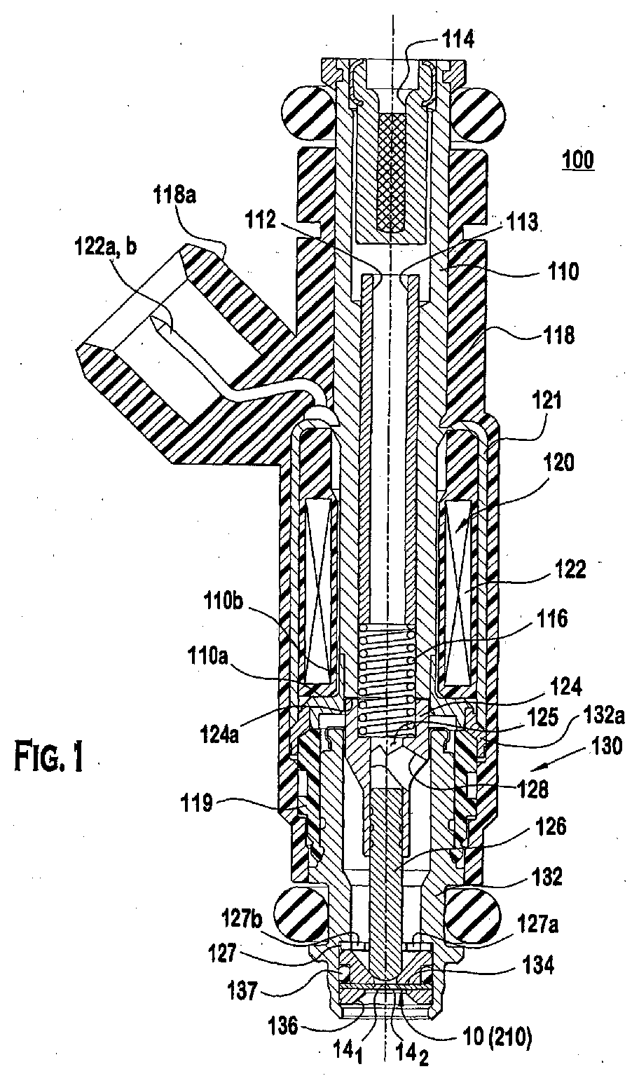
- Fig 1 illustrates a fuel injector with an orifice of a preferred embodiment.
- Figs. 2a-2e illustrate the characteristics of an orifice and orifice plate in Fig. 1 prior to the formation of the angled orifice and after the formation of the angled orifice.
- Figs. 3a-3c illustrates the formation of an angled orifice in an orifice plate according to another preferred embodiment.
- Figs. 4a-4c illustrate the formation of an angled orifice in an orifice plate according to yet another preferred embodiment.
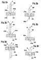
- Figs. 5a-5f illustrate the formation of an angled orifice in an orifice plate according to yet a further embodiment.
- Figs. 1-5 illustrate certain embodiments of the present invention.
- a fuel injector 100 comprising an embodiment of the orifice plate 10 is illustrated in Fig. 1.
- the fuel injector 100 includes a fuel inlet tube 110, an adjustment tube 112, a filter assembly 114, a coil assembly 118, a coil spring 116, an armature 124, a closure member 126, a non-magnetic shell 110a, a first overmould 118, a valve body 132, a valve body shell 132a, a second overmould 119, a coil assembly housing 121, a guide member 127 for the closure member 126, a valve seat 134, an orifice plate 10, a backup retainer member 136, and an O-ring seal 137.
- the guide member 127, the valve seat 134, the orifice plate 10, the backup retainer member 136, and the small O-ring seal 137 form a stack that is disposed at the outlet end of fuel injector 100, as shown in a number of commonly assigned patents, such as U.S. Pat. No. 5,174,505.
- Armature 124 and the closure member 126 are joined together to form an armature/needle valve assembly. It should be noted that one skilled in the art could form the assembly from a single component.
- Coil assembly 120 comprises a plastic bobbin on which an electromagnetic coil 122 is wound.
- Respective terminations of coil 122 connect to respective terminals 122a, 122b that are shaped and, in co-operation with a surround 118a formed as an integral part of overmould 118, to form an electrical connector for connecting the fuel injector to an electronic control circuit (not shown) that operates the fuel injector.
- Fuel inlet tube 110 can be ferromagnetic and comprises a fuel inlet opening at the exposed upper end.
- Filter assembly 114 can be fitted proximate to the open upper end of adjustment tube 112 to filter any particulate material larger than a certain size from fuel entering through inlet opening before the fuel enters adjustment tube 112.
- adjustment tube 112 has been positioned axially to an axial location within fuel inlet tube 110 that compresses preload spring 116 to a desired bias force that urges the armature/needle valve such that the rounded tip end of closure member 126 can be seated on valve seat 134 to close the central hole through the valve seat.
- tubes 110 and 112 are crimped together to maintain their relative axial positioning after adjustment calibration has been performed.
- Armature 124 comprises a passageway 128 that communicates volume 125 with a passageway 113 in valve body 130, and guide member 127 contains fuel passage holes 127a, 127b. This allows fuel to flow from volume 125 through passageways 113, 128 to valve seat 134.
- Non-ferromagnetic shell 110a can be telescopically fitted on and joined to the lower end of inlet tube 110, as by a hermetic laser weld.
- Shell 110a has a tubular neck that telescopes over a tubular neck at the lower end of fuel inlet tube 110.
- Shell 110a also has a shoulder that extends radially outwardly from neck.
- Valve body shell 132a can be ferromagnetic and can be joined in fluid-tight manner to non-ferromagnetic shell 110a, preferably also by a hermetic laser weld.
- valve body 130 fits closely inside the lower end of valve body shell 132a and these two parts are joined together in fluid-tight manner, preferably by laser welding.
- Armature 124 can be guided by the inside wall of valve body 130 for axial reciprocation. Further axial guidance of the armature/needle valve assembly can be provided by a central guide hole in member 127 through which closure member 126 passes.
- Non-ferromagnetic shell 110a assures that when electromagnetic coil 122 is energised, the magnetic flux will follow a path that includes armature 124.
- the magnetic circuit extends through valve body shell 132a, valve body 130 and eyelet to armature 124, and from armature 124 across working gap 72 to inlet tube 110, and back to housing 121.
- electromagnetic coil 122 When electromagnetic coil 122 is energised, the spring force on armature 124 can be overcome and the armature is attracted toward inlet tube 110 reducing working gap 72.
- the actuator may be mounted such that a portion of the actuator can disposed in the fuel injector and a portion can be disposed outside the fuel injector.
- preload spring 116 pushes the armature/needle valve closed on valve seat 134.
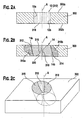
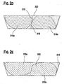
- Figures 2a and 2b show respective side view of an orifice 12 of a workpiece 300 and the transformation of orifice 12 into an angled orifice 14.
- the orifice 12 is formed in the work piece 300, shown in Fig. 2a.
- the orifice 12 is defined by orifice surfaces 12a and 12b having generally uniform surface characteristics throughout.
- materials on the orifice surfaces 12a and 12b are removed and sheared away, leaving behind generally parallel ridges or region 310 uniformly distributed about the circumferential surface of the orifice 12, shown in Fig. 2b.
- a transition region 320 is formed between a first area 318a bounded by partial sections of the plate surfaces 302a, 302b and line 316 and a second area 318a bounded by partial sections of surfaces 302a, 302b and line 318.
- the first bounded area 316a has surface characteristics oriented in a first direction due to the movement of the first tool head, which causes a change in the crystalline structure of the material of the orifice.
- the orifice is unrolled in Figs 2d and 2e. That is, Figs 2d and 2e illustrate a 360 degrees panoramic view of the surfaces of the orifice as viewed by an observer rotating about the longitudinal axis A-A within the orifice. As seen in the "virtual" unrolling of the orifice 14 in Figs.
- the second bounded area 318a has surface characteristics oriented in a second direction different from the first direction due to the movement of the second tool head, which also causes a change in the crystalline structures of the orifice plate. It should be noted that the crystalline structures of the transition region could be different from the crystalline structures of the first and second bounded areas. Similarly, the crystalline structures of the first bounded area can be different from the second bounded area.
- first and second bounded areas 316a, 318a are shown as being bounded by partial sections of the surfaces 302a, 302b and two lines 316 and 318, in certain cases, depending on the geometries of the cutting tool(s) and other dimensional parameters of the orifice, the line 316 can merge with line 318 so as to define a single continuous line 322 between the two contiguous first and second areas in place of the transition region 320, shown here in Fig. 2e.
- Figs 3a-3c illustrate one technique of how the perpendicular orifice 12 in Fig. 2a can be transformed into an angled orifice 14 in Fig. 2b.
- this technique illustrates a generally simultaneous formation of a right-angled orifice 12 to an angled orifice 14 for plate 10.
- Figs. 2a-2c illustrate another technique that allows sequential formation of a right-angled orifice 12 to an angled orifice 14 in the orifice plate.
- the term "orifice” denotes an "opening" that extends between a first surface 10a to a second surface 10b of a member, which is preferably is a plate.
- the "opening" can be of a suitable cross-section, such as, for example, circular, oval, rectangular, square or polygonal.
- the orifice has a circular opening with straight orifice surfaces 12a and 12b (of orifice 12) and an oval opening subsequent to the formation of angled orifice surfaces 14a and 14b (of orifice 14).
- the orifice plate 10 can include a member of a suitable cross-section, such as, for example, a plate with a first surface 10a that can be linear and preferably parallel to a linear second surface 10b; a plate having non-parallel first surface 10a (which can be a substantially planar surface) to the second surface 10b (which can also be a substantially planar surface); or a plate with a first surface 10a that can be curvilinear and preferably parallel to a curvilinear second surface 10b.
- the orifice 10 can include a right-angled orifice 12 pre-formed thereon or the right-angled orifice 12 can be formed prior to the formation of the angled orifice 14.
- the formations of the right-angled orifice can be done prior to the formation of an angled orifice.
- the right-angled orifice 12 can be formed by a suitable technique, such as, for example, electro-discharge-machining (EDM), laser drilling or by mechanical drilling/punching.
- EDM electro-discharge-machining
- the plate or metal sheet can be between approximately 0.003 - 0.010 inch (76.2-254.0 microns) in thickness.
- the plate can be any suitable material, such as, for example, metal, composite, monomer or polymer that deforms upon application of a compressive load.
- the orifice plate 10 can be a stainless steel plate or sheet having linearly parallel first and second surfaces 10a and 10b separated by a distance of approximately 0.006 inch (152.4 microns), which plate also has an orifice 12 pre-formed by a suitable technique such as, for example, by mechanical drilling, punching, laser drilling or by Electric Discharge Machining.
- an orifice plate 10 can be provided with a preformed orifice 12 of a first predetermined cross-sectional area A 1 .
- the first cross-sectional area A 1 is referenced as an area generally transverse to the axis A on either surface 302a or 302b.
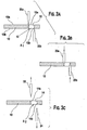
- a first punch tool 20a and a second punch tool 20b are placed on opposite sides of the plate 10 such that a longitudinal axis extending along each of the tool is substantially parallel to the longitudinal axis A.
- the first punch tool 20a can be provided with a first tip 22 having a suitable cross-section, such as, for example, a cone, a right triangle, square, polygonal or a wedge.
- the second punch tool 20b can be provided with a second tip 24 having a suitable cross-section, such as, for example, a cone, a right triangle, square, polygonal or a wedge.
- the tips 22 and 24 are conic.
- the formation of the orifice 14 can be performed in sequence by the tool heads as a function of the speed of the press and size and progression of the die.
- Each of the tips 22 and 24 can be aligned such that, as each tip is moved towards the orifice 12, the respective tip can be contiguous to a portion of the edge of the orifice 12 (Figs. 3a and 4a). As each tip is further moved in a direction along the axis A (Fig. 3b), the orifice surfaces 12a and 12b are plastically deformed, resulting in a permanent deformation of the orifice surfaces 10a and 10b (Figs. 2b and 3c). Although the wall surfaces have been described as separate portions, it should be understood that each surface is part of an area defining the orifice.
- Each of the orifice surfaces 12a and 12b can be deformed into respective orifice surfaces 14a and 14b that are oblique with respect to the longitudinal axis, or at least one orifice surface is oblique to both the axis A and the other orifice surface (Fig. 2b).
- the walls surfaces 14a, 14b are deformed so as to define a second predetermined cross-sectional area A 2 (as referenced generally transverse to axis A) of the orifice 14 where A 2 >A 1 of the area of the orifice 12.
- some materials from the orifice surfaces 10a and 10b are removed while other materials of the orifice surfaces are plastically deformed.
- each tip can plastically deform the wall or orifice surfaces of the orifice 12
- an orifice plate 10 is again preferably provided with an orifice 12 having its surface extending along the axis A.
- One of the first and second surfaces 10a and 10b can be placed against a first die bushing 30a.
- the punch tool can be used to plastically deform the orifice surfaces 10a or 10b from the other of the first and second surfaces 10a, 10b (Figs. 4a and 4b) by moving the punch tool along a first axis B that can be parallel and offset to the axis A. This results in an orifice plate 10 having a orifice surface 14a oriented in an oblique direction relative to the axis A.
- the plate 10 is then moved along a direction X.
- a second die bushing 30b can be placed against the other of the first and second surfaces 10a and 10b (i.e. surface 10a) while the second punch tool 20b can be moved along a second axis C parallel to and offset to axis A.
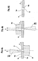
- a first punch tool 200 can be used to punch a first surface 210a of a metal sheet 210, a first orifice 212 having orifice surfaces 212a and 212b perpendicular to one of the first and second substantially planar surfaces 210a and 210b of the metal sheet 210, which first punch tool can be used to deform the first surface 210a to a first oblique orifice surface 211 a of the orifice and a second punch tool 202 can be used to deform the second orifice surfaces 210b to a second oblique orifice surface 211b.
- the first punch tool 200 can be moved in a first axis A that can be perpendicular to one of the first and second surfaces 210a and 210b (Fig. 5a). As the first punch tool moves through the metal sheet 210, an orifice 212 having parallel orifice surfaces 212a and 212b are formed (Fig. 5b). The first punch tool is then withdrawn and is translated by a predetermined offset from the axis A, such that a tip 200a can be generally contiguous to one of edges 212c and 212d formed between the surfaces 210a, 210b and the orifice surfaces 212a and 212b (Fig. 5c).
- the first punch tool 200 can be moved along a second axis B, which axis B is preferably parallel to the first axis A, and can be also perpendicular to one of the surfaces 210a and 210b so as to plastically deform the first orifice surface 212a to a first oblique orifice surface 213a (Fig. 5d).
- the second punch tool 202 which could be an identical punch tool to the first punch tool 200, can be aligned with a third axis C such that, preferably, a tip 202a, is contiguous with the edge 212d of the orifice 212.
- the third axis C can be preferably parallel to and offset by a predetermined distance from the first axis A.
- the tip 202a plastically deforms the orifice surface 212b of the orifice 212 so as to form a second oblique orifice surface 213b.
- the first oblique orifice surface 213a and the second oblique orifice surface 213b are preferably parallel to each other and oblique with respect to the first axis A. It should be noted here that, instead of a second punch tool, the workpiece could be flipped 180 degrees such that the first punch tool can be used to also punch surface 210b.
- an area that is formed by an opening of the oblique orifice 213 could be greater than an area that is formed by an opening of the orifice 212. Further details of the processes involved in forming the angled orifice are described in later parts of the present description.
- plastic deformation indicates that a material 300 of the orifice plate 10, specifically the orifice 12, can be deformed beyond the elastic limit, thereby resulting in a permanent deformation of the material in a surrounding area 310 (Figs. 1a-1c).
- the permanently deformed material may provide a characteristic bulged or raised portion 312 or 314 of plastically deformed material bulging away from the planar surface near respective intersections between the orifice and the surfaces 302a or 302b of the orifice 14 or 213.
- the surrounding area 310 of the orifice 14 or 212 can be hardened by cold-working.
- Cold-worked metal results in new dislocations being produced when the metal is deformed. As the number of dislocations in the crystal change, they should become tangled or pinned and would not be able to move. This should strengthen the material near or surrounding the orifice plate, which should make the plate as whole harder to deform due to the cold working process.
- compressive stresses are beneficial in increasing resistance to fatigue failures, corrosion fatigue, stress corrosion cracking, hydrogen assisted cracking, fretting, galling and erosion caused by fluid flow cavitation.
- the orifice 14 or 213 may also benefit due to work hardening, intergranular corrosion resistance, surface texturing and closing of porosity in the metal.
- the cold working, or expansion, of the orifice 14 or 213 creates compressive stress zones around the orifice. These compressive stress zones around the orifice 14 or 213 should provide an increase in hardness and improved fatigue resistance of the material that the orifice is made of.
- the cold-worked metal plate or metal sheet used to form the orifice disc can also be heat treated by a suitable heat treatment such as, for example, annealing, process-annealing, normalising, patenting, spherodizing, or tempering for one or more purposes such as (1) to remove stresses; (2) to induce softness; (3) to alter ductility, toughness, electrical; magnetic or other physical properties; (4) to refine the crystalline structure; (5) to remove gases; or (6) to produce a desired micro-structure for the sheet metal or plate.
- a suitable heat treatment such as, for example, annealing, process-annealing, normalising, patenting, spherodizing, or tempering for one or more purposes such as (1) to remove stresses; (2) to induce softness; (3) to alter ductility, toughness, electrical; magnetic or other physical properties; (4) to refine the crystalline structure; (5) to remove gases; or (6) to produce a desired micro-structure for the sheet metal or plate.
- the following, second, part of the present invention relates to a method of forming angled orifices in an orifice plate.
- An electro-magnetic fuel injector typically utilises a solenoid assembly to supply an actuating force to a fuel-metering valve.
- the fuel metering valve is a plunger-style needle valve which reciprocates between a closed position, where the needle is seated in a valve seat to prevent fuel from escaping through a metering orifice into the combustion chamber, and an open position, where the needle is lifted from the valve seat, allowing fuel to discharge through the metering orifice for introduction into the combustion chamber.
- Fuel flowing through a fuel injector typically exits at an outlet end of the fuel injector.
- the outlet end is believed to have a disk or plate with at least one orifice to control, in part, the spray pattern and the direction of the fuel exiting the fuel injector.
- An orifice extending along an axis perpendicular to a surface of a work piece is believed to be formed by drilling or by punching through the work piece.
- One method of drilling is by electric discharge machining (EDM) that can form orifices of 150 to 200 microns in diameter. It is believed that one of the many disadvantages of EDM is the fact that the holes are typically formed without any favourable entry or exit geometry for the orifices, thereby affecting the flow through the orifices.
- Another method is by laser machining the orifices on the work piece or the plate.
- Yet another method can be by stamping or punching the orifices and then coining each edge of the orifice.
- the orifices formed by these methods do not allow for spray targeting of the fuel as the fuel leaves the orifices of the injector.
- orifices can be angled to a desired angle relative to a longitudinal axis of the fuel injector. Such angled orifices can be formed by any of the above methods, albeit at, it is believed, a much greater cost than a straight orifice.
- Another method utilises dimpling a portion of the work piece on which a straight orifice has already been formed with a right circular cone.
- dimpled orifice plate increases a sac volume between the fuel injector closure tip and the orifice plate. This increased sac volume, during a non-injection event, causes fuel to remains in the sac that vaporises and causes rich/lean shifts and hot start issues, which are undesirable.
- the second part of the present invention provides several methods of forming angled orifices in a workpiece with a plurality of angled orifices.
- the present invention provides for one method of forming orifices in a metal sheet, each having an oblique axis relative to at least one of a first surface and a second surface of a metal sheet.
- the method can be achieved by punching the metal sheet in a first direction along a first axis perpendicular to one of the first and second surfaces of the metal sheet with a first tool piece so as to form a first orifice, the first orifice defining an opening having wall surfaces parallel to the first axis; and punching the metal sheet with the first tool piece proximate the first orifice in the first direction along a second axis parallel and offset to the first axis so as to form a first wall surface of the first orifice extending between the first and second surfaces of the metal sheet oblique to the first axis.
- the present invention also provides for another method of forming a plurality of orifices for an orifice plate.
- the orifice plate has a first plate surface and a second plate surface spaced from the first plate surface.
- the method can be achieved by providing a first tool head, a second tool head, a plurality of orifices extending between the first and second plate surfaces of the plate along a longitudinal axis perpendicular to at least one of the first and second surfaces, each of the plurality of orifices having wall surfaces parallel to the longitudinal axis and intersecting the first and second plate surfaces so as to define an edge of the orifice; moving one of the first tool head and the plate in a first direction along the longitudinal axis into one of the first a second plate surfaces at a location proximate an edge of each of the plurality of orifices so as to cause a first portion of the wall surfaces to extend in a first oblique direction relative to the longitudinal axis; and moving the other of the second tool head and the
- Figs. 1'a-1'c illustrate two punches and a work plate involved in the process of a certain embodiment.
- Figs. 2'a-2'c illustrate two punches and a work plate in another embodiment.
- Fig. 3'a-3'f illustrate a process of forming an orifice with a single punch according to yet another embodiment.
- Fig. 4'a illustrates a cross-sectional cutaway of an orifice plate with a straight orifice.
- Fig. 4'b illustrates a cross-sectional cutaway of an angled orifice with plastic deformations.
- Fig. 4'c illustrates an orthogonal view of the oblique orifice of Fig. 4'b with exaggerated delineation of surface changes to due to certain embodiments.
- Figs. 4'd and 4'e illustrate a virtual oblique orifice being unrolled from the orifice of Figs. 4'b-4'c.
- Fig. 5' illustrates the orifice plate and the angled orifice in a fuel injector.
- Figs. 1'-5' illustrate certain embodiments of the second part of the present invention.
- Figs 1'a-1'c illustrate a generally simultaneous formation of an angled orifice 14 from a right-angled orifice 12 for an orifice plate 10.
- Figs. 2'a-2'c illustrate a sequential formation of the angled orifice 14 from a right-angled orifice 12 for an orifice plate.
- the term "orifice” denotes an "opening" that extends between a first surface 10a to a second surface 10b of a member, which preferably is a plate.
- the opening can be of a suitable cross-section, such as, for example, circular, oval, rectangular, square or polygonal.
- the orifice has a circular opening with straight wall surfaces 12a and 12b (of orifice 12) and an oval opening subsequent to the formation of angled wall surfaces 14a and 14b (of orifice 14).
- the orifice plate 10 can include a member of a suitable cross-section, such as, for example, a plate with a first surface 10a that can be linear and preferably parallel to a linear second surface 10b; a plate having non-parallel first surface 10a (which can be a substantially planar surface) to the second surface 10b (which can also be a substantially planar surface); or a plate with a first surface 10a that can be curvilinear and preferably parallel to a curvilinear second surface 10b.
- the orifice 10 can include a right-angled orifice 12 pre-formed thereon or the right-angled orifice 12 can be formed prior to the formation of the angled orifice 14.
- the formations of the right-angled orifice can be done prior to the formation of an angled orifice.
- the right-angled orifice 12 can be formed by a suitable technique, such as, for example, electro-discharge-machining (EDM), laser drilling or by mechanical drilling/punching.
- EDM electro-discharge-machining
- the plate or metal sheet can be between approximately 0.003 - 0.010 inch (76.2 - 254.0 microns) in thickness.
- the plate can be any suitable material, such as, for example, metal, composite, monomer or polymer that deforms upon application of a compressive load.
- the orifice plate 10 can be a stainless steel plate or sheet having linearly parallel first and second surfaces 10a and 10b separated by a distance of approximately 0.006 inch (152.4 microns), which plate also has an orifice 12 pre-formed by a suitable technique such as, for example, by mechanical drilling, punching, laser drilling or by Electric Discharge Machining.
- an orifice plate 10 can be provided with a preformed orifice 12 of a first predetermined cross-sectional area A 1 extending along a longitudinal axis A.
- the first cross-sectional area A 1 is referenced as an area generally transverse to the axis A on either surface 302a or 302b.
- a first punch tool 20a and a second punch tool 20b are placed on opposite sides of the plate 10 such that a longitudinal axis extending along each of the tool is substantially parallel to the longitudinal axis A.
- the first punch tool 20a can be provided with a first tip 22 having a suitable cross-section, such as, for example, a cone, a right triangle or a wedge.
- the second punch tool 20b can be provided with a second tip 24 having a suitable cross-section, such as, for example, a cone, a right triangle or a wedge.
- the tips 22 and 24 are conic.
- the formation of the orifice 14 can be performed in sequence by the tool heads depending the speed of the press and size and progression of the die.
- Each of the tips 22 and 24 can be aligned such that, as each tip is moved towards the orifice 12, the respective tip can be contiguous to a portion of the edge of the orifice 12 (Figs. 1'a and 3'). As each tip is further moved in a direction along the axis A (Fig. 1'b), the wall or orifice surfaces 12a and 12b are believed to be plastically deformed, resulting in a permanent deformation of the wall or orifice surfaces 10a and 10b (Figs. 1'c and 4'b). Although the wall surfaces have been described as separate portions, it should be understood that each surface is part of an area defining the orifice.
- Each of the wall or orifice surfaces 12a and 12b can be deformed into respective wall or orifice surfaces 14a and 14b that are oblique with respect to the longitudinal axis, or at least one wall surface can be oblique to both the axis A and the other wall surface (Fig. 4'b). Moreover, due to the punch tools, the walls surfaces 14a, 14b are deformed to a second predetermined cross-sectional area A 2 (as referenced generally transverse to axis A) of the orifice 14 where A 2 >A 1 of the area of the orifice 12. Furthermore, some materials from the wall or orifice surfaces 10a and 10b are removed while other materials of the wall or orifice surfaces are plastically deformed.
- each tip can plastically deform the wall or orifice surfaces of the orifice 12
- an angled orifice can be done in sequence in another preferred embodiment, shown here in Figs 2'a-2'c.
- an orifice plate 10 can be again preferably provided with an orifice 12 having a right circular opening with extends generally along the longitudinal axis to form the surfaces of the orifice.
- One of the first and second surfaces 10a and 10b can be placed against first die bushing 30a.
- the punch tool can be used to plastically deform the wall or orifice surfaces 10a or 10b from the other of the first and second surfaces 10a, 10b (Figs. 2'a and 2'b) by moving the punch tool along a first axis B that can be parallel and offset to the axis A.
- an orifice plate 10 having a wall surface 14a oriented in an oblique direction relative to the axis A.
- the plate 10 is then moved along a direction X.
- a second die bushing 30b can be placed against the other of the first and second surfaces 10a and 10b (i.e. surface 10a) while the second punch tool 20b can be moved along a second axis C parallel to and offset to axis A.
- a first punch tool 200 can be used to punch, in a metal sheet 210, a first orifice 212 having wall or orifice surfaces 212a and 212b perpendicular to one of the first and second surfaces 210a and 210b of the metal sheet 210, which first punch tool can be used to deform the first surface 210a to a first oblique wall surface 211a of the orifice and a second punch tool 202 can be used to deform the second wall or orifice surfaces 210b to a second oblique wall surface 211b.
- the first punch tool 200 can be moved in a first axis A that can be perpendicular to one of the first and second surfaces 210a and 210b (Fig. 3'a). As the first punch tool moves through the metal sheet 210, an orifice 212 having parallel wall or orifice surfaces 212a and 212b are formed (Fig. 3'b). The first punch tool can be withdrawn and can be preferably offset from the axis A by a predetermined distance such that a tip 200a can be generally contiguous to one of edges 212c and 212d formed between the surfaces 210a, 210b and the wall or orifice surfaces 212a and 212b (Fig. 3'c).
- the first punch tool 200 is then moved along a second axis B, which axis B can be preferably parallel to the first axis A, and is also perpendicular to one of the surfaces 210a and 210b so as to plastically deform the first wall surface 212a to a first oblique wall surface 213a (Fig. 3'd).
- the second punch tool 202 which could be an identical punch tool to the first punch tool 200, can be aligned with a third axis C such that, preferably, a tip 202a, can be contiguous with the edge 212d of the orifice 212.
- the third axis C can be preferably parallel to and offset by a predetermined distance from the first axis A.
- the tip 202a plastically deforms the wall surface 212b of the orifice 212 so as to form a second oblique wall surface 213b.
- the first oblique wall surface 213a and the second oblique wall surface 213b are preferably parallel to each other and oblique with respect to the first axis A.
- the workpiece could be flipped 180 degrees such that the first punch tool can be used to also punch surface 210b.
- an area that can be formed by an opening of the oblique orifice 213 can be now greater than an area that can be formed by an opening of the orifice 212.
- plastic deformation indicates that a material 300 of the orifice plate 10, specifically the orifice 12, can be deformed beyond the elastic limit, thereby resulting in a permanent deformation of the material in a surrounding area 310 (Figs. 4'a-4'c).
- the permanently deformed material may provide a characteristic bulged or raised portion 312 or 314 of plastically deformed material bulging away from the planar surface near respective intersections between the orifice and the surfaces 302a or 302b of the orifice 14 or 213.
- the surrounding area 310 of the orifice 14 or 212 can be hardened by cold-working.
- Cold-worked metal results in new dislocations being produced when the metal is deformed. As the number of dislocations in the crystal change, they should become tangled or pinned and would not be able to move. This should strengthen the material near or surrounding the orifice plate, which should make the plate as whole harder to deform due to the cold working process.
- compressive stresses are beneficial in increasing resistance to fatigue failures, corrosion fatigue, stress corrosion cracking, hydrogen assisted cracking, fretting, galling and erosion caused by fluid flow cavitation.
- the orifice 14 or 213 may also benefit due to work hardening, intergranular corrosion resistance, surface texturing and closing of porosity in the metal.
- the cold working, or expansion, of the orifice 14 or 213 creates compressive stress zones around the orifice. These compressive stress zones around the orifice 14 or 213 should provide an increase in hardness and improved fatigue resistance of the material that the orifice is made of.
- the cold-worked metal plate or metal sheet used to form the orifice disc can also be heat treated by a suitable heat treatment such as, for example, annealing, process-annealing, normalising, patenting, spherodizing, or tempering for one or more purposes such as (1) to remove stresses; (2) to induce softness; (3) to alter ductility, toughness, electrical, magnetic or other physical properties; (4) to refine the crystalline structure; (5) to remove gases; or (6) to produce a desired micro-structure for the sheet metal or plate.
- a suitable heat treatment such as, for example, annealing, process-annealing, normalising, patenting, spherodizing, or tempering for one or more purposes such as (1) to remove stresses; (2) to induce softness; (3) to alter ductility, toughness, electrical, magnetic or other physical properties; (4) to refine the crystalline structure; (5) to remove gases; or (6) to produce a desired micro-structure for the sheet metal or plate.
- a transition region 320 can be formed between a first area 318a bounded by partial sections of the plate surfaces 302a, 302b and line 316 and a second area 318a bounded by partial sections of surfaces 302a, 302b and line 318.
- the first bounded area 316a has surface characteristics oriented in a first direction due to the movement of the first tool head, which causes a change in the crystalline structure of the material of the orifice. To better illustrate the characteristics of the angled orifice, the orifice is unrolled in Figs 4'd and 4'e.
- Figs 4'd and 4'e illustrate a 360 degrees panoramic view of the surfaces of the orifice as viewed by an observer rotating about the longitudinal axis A within the orifice.
- the second bounded area 318a has surface characteristics oriented in a second direction different from the first direction due to the movement of the second tool head, which also causes a change in the crystalline structures of the orifice plate.
- a crystalline structure of the transition region could be different from a crystalline structure of the first and second bounded areas.
- the crystalline structure of the first bounded area can be different from that of the second bounded area.
- first and second bounded areas 316a, 318a are shown as being bounded by partial sections of the surfaces 302a, 302b and two lines 316 and 318, in certain cases, depending on the geometries of the cutting tool(s) and other dimensional parameters of the orifice, the line 316 can merge with line 318 so as to define a single continuous line 322 between the two contiguous first and second areas in place of the transition region 320, shown here in Fig. 4'e.
- one of several methods of forming an angled orifice can be performed by punching the metal sheet 210 in a first direction along a first axis A perpendicular to one of the first and second surfaces 210a, 210b of the metal sheet with a first tool piece 200 so as to form a first orifice.
- the first orifice 12 defines an opening having wall surfaces 212a, 212b parallel to the first axis.
- This method is further performed by punching the metal sheet 210 with the first tool piece 200 proximate the first orifice 210 in the first direction along a second axis B parallel and offset to the first axis so as to form a first wall surface 213a of the first orifice 213 extending between the first and second surfaces of the metal sheet and being oblique to the first axis A. Further, the method is also performed by punching the metal sheet 210 with the first tool piece 200 or with a second tool piece 202 proximate the first orifice in a second direction along a third axis parallel C and offset to the first axis A so as form a second wall surface 213b of the first orifice oblique to the first axis A.
- Another method of forming an angled orifice can also be performed by providing first and second tool heads 20a, 20b and a plurality of pre-formed orifices 12 extending between the first and second plate surfaces 10a, 10b along a longitudinal axis A.
- Each of the plurality of orifices has wall surfaces 12a, 12b parallel to the longitudinal axis A and intersecting the first and second plate surfaces 10a, 10b so as to define an edge of the orifice.
- This method is performed, in part, by moving one of the first tool head 20a and the plate 10 in a first direction along the longitudinal axis into one of the first a second plate surfaces 10a, 10b at a location proximate an edge (similar to edge 212c of Fig.
- this method is performed, in part, by moving the other of the second tool head 20b and the plate 10 in a second direction along the longitudinal axis A into the other of the first and second plate surfaces 10a, 10b at a location proximate an edge of each of the plurality of orifices 12 so as to cause a second portion of the wall surfaces to extend in a second oblique direction relative to the longitudinal axis A.
- the moving feature of this method can further include moving one of the first tool head 20a and the plate 10 in a first direction during a first predetermined time interval t1 and moving in the second direction further comprises moving one of the second tool head and the plate in a second direction opposite to the first direction during a second predetermined time interval t2.
- the method includes displacing the first portion of the wall surfaces of each of the plurality of orifices proximate one of the first and second surfaces in the first oblique direction to the longitudinal axis.
- the method includes displacing the second portion of the wall surfaces 12a, 12b of each of the plurality of orifices proximate the other of the first and second plate surfaces 10a, 10b in the second oblique direction relative to the longitudinal axis A.
- the displacing can also include causing the one of the first and second portions of the wall surfaces 12a, 12b to deform such that the one portion is generally parallel to a narrowed portion of the first tool head 20a, and causing the other of the first and second portions of the wall surfaces to deform such that the other portion is generally parallel to a narrowed portion of the second tool head 20b.
- the fuel injector illustrated here in Fig. 5' as injector 100, includes an inlet tube 110, electromagnetic actuator 120 and a valve assembly 130.
- the ) electromagnetic actuator 120 can include an electromagnetic coil 122, an armature 124 and a closure member 126 coupled thereto.
- the valve assembly 130 can include a valve body 132, a valve seat 134 and an orifice plate 10 or metal sheet 210.
- a plurality of orifices 14 1 and 14 2 can be formed for the orifice plate 10 or metal sheet 210 in accordance with the preferred embodiments discussed above. Thereafter, the orifice plate can be assembled with other components of the fuel injector 100. Additional details are set forth in U.S. Pat. No. 5,494,225 issued on Feb. 27, 1996, which is incorporated in its entirety herein by reference.
- a method of forming orifices in a metal sheet, each orifice having an oblique axis relative to at least one of a first surface and a second surface of a metal sheet comprising: punching the metal sheet in a first direction along a first axis perpendicular to one of the first and second surfaces of the metal sheet with a first tool piece so as to form a first orifice, the first orifice defining an opening having wall surfaces parallel to the first axis; and punching the metal sheet with the first tool piece proximate the first orifice in the first direction along a second axis parallel and offset to the first axis so as to form a first wall surface of the first orifice extending between the first and second surfaces of the metal sheet oblique to the first axis.
- each of the tool heads comprises a pointed tip punch.
- a method of forming a plurality of orifices for an orifice plate, the orifice plate having a first plate surface and a second plate surface spaced from the first plate surface comprising: providing first and second tool heads and a plurality of orifices extending between the first and second plate surfaces along a longitudinal axis, each of the plurality of orifices having wall surfaces parallel to the longitudinal axis and intersecting the first and second plate surfaces so as to define an edge of the orifice; moving one of the first tool head and the plate in a first direction along the longitudinal axis into one of the first a second plate surfaces at a location proximate an edge of each of the plurality of orifices so as to cause a first portion of the wall surfaces to extend in a first oblique direction relative to the longitudinal axis; and moving the other of the second tool head and the plate in a second direction along the longitudinal axis into the other of the first and second plate surfaces at a location proximate an edge of each of
- moving in the first direction further includes moving one of the first tool head and the plate in a first direction during a first predetermined time interval and moving in the second direction further comprises moving one of the second tool head and the plate in a second direction opposite to the first direction during a second predetermined time interval.
- the displacing further comprises causing the other of the first and second portions of the wall surfaces to deform such that the other portion is generally parallel to a surface of the second tool head.
- each of the tool heads comprises a pointed tip punch.
Landscapes
- Engineering & Computer Science (AREA)
- Mechanical Engineering (AREA)
- Chemical & Material Sciences (AREA)
- Combustion & Propulsion (AREA)
- General Engineering & Computer Science (AREA)
- Manufacturing & Machinery (AREA)
- Physics & Mathematics (AREA)
- Electromagnetism (AREA)
- Fuel-Injection Apparatus (AREA)
Abstract
Description
- A first part of the present invention relates to a fuel injector having an orifice plate with offset coining angled orifices.
- Most modern automotive fuel systems utilise fuel injectors to provide precise metering of fuel for introduction into each combustion chamber. Additionally, the fuel injector atomises the fuel during injection, breaking the fuel into a large number of very small particles, increasing the surface area of the fuel being injected, and allowing the oxidiser, typically ambient air, to more thoroughly mix with the fuel prior to combustion. The precise metering and atomisation of the fuel reduces combustion emissions and increases the fuel efficiency of the engine.
- An electro-magnetic fuel injector typically utilises a solenoid assembly to supply an actuating force to a fuel-metering valve. Typically, the fuel metering valve is a plunger-style needle valve which reciprocates between a closed position, where the needle is seated in a valve seat to prevent fuel from escaping through a metering orifice into the combustion chamber, and an open position, where the needle is lifted from the valve seat, allowing fuel to discharge through the metering orifice for introduction into the combustion chamber.
- Fuel flowing through a fuel injector typically exits at an outlet end of the fuel injector. The outlet end typically have a disk or plate with at least one orifice to control, in part, the spray pattern and the direction of the fuel exiting the fuel injector.
- An orifice extending along an axis perpendicular to a surface of a work piece (i.e. a straight orifice) is believed to be formed by drilling or by punching through the work piece. One method of drilling is by electric discharge machining (EDM) that can form orifices of 150 to 200 microns in diameter. It is believed that one of the many disadvantages of EDM is the fact that the holes are typically formed without any favourable entry or exit geometry for the orifices, thereby affecting the flow through the orifices. Another method is by laser machining the orifices on the work piece or the plate. Yet another method can be by stamping or punching the orifices and then coining each edge of the orifice. However, it is believed that the orifices formed by these methods do not allow for spray targeting of the fuel as the fuel leaves the orifices of the injector.
- In order to target the fuel spray, it is believed that orifices can be angled to a desired angle relative to a longitudinal axis of the fuel injector. Such angled orifices can be formed by any of the above methods, albeit at, it is believed, a much greater cost than a straight orifice. Another method utilises dimpling a portion of the work piece on which a straight orifice has already been formed with a right circular cone. However, it is believed that such dimpled orifice plate increases a sac volume between the fuel injector closure tip and the orifice plate. This increased sac volume, during a non-injection event, causes fuel to remain in the sac that vaporises and causes rich/lean shifts and hot start issues, which are undesirable.
- Briefly, the present invention provides a plurality of angled orifices on a work piece and a method of forming such angled orifices. The present invention also provides for a fuel injector. The fuel injector has a housing extending along a longitudinal axis, the housing including an inlet, an outlet and a passageway disposed between the inlet and the outlet. The fuel injector includes an electromagnetic actuator proximate the inlet and an orifice plate proximate the outlet. The electromagnetic actuator having an armature, an electromagnetic coil a closure member and a valve seat. The closure member is operable to occlude fuel flow to the outlet in a first position and is operable to permit fuel flow to the outlet in a second position. The orifice plate is located proximate the outlet, the orifice plate having first and second plate surfaces spaced at a predetermined distance along a longitudinal axis and an orifice. The orifice includes a first surface and a second surface being spaced from the first surface. The first surface includes a first region having a first surface characteristic being oriented in a first direction oblique to the longitudinal axis. The second surface includes a second region having second surface characteristic being oriented in a second direction oblique to longitudinal axis.
- The present invention also provides for a valve assembly for controlling fluid flow. The valve assembly comprises a body having a first end and a second end, an actuator disposed in the body, a closure member operable by the actuator to occlude fluid flow in one position and operable to permit flow in another position, a surface contiguous to the closure member in the one position so as to form a sealing surface, and an orifice plate proximate one of the first and second ends. The orifice plate includes first and second plate surfaces spaced at a predetermined distance from one another along a longitudinal axis, and an orifice. The orifice including a first orifice surface and a second orifice surface being spaced from the first orifice surface. The first orifice surface has a first region including a first surface characteristic being oriented in a first direction oblique to the longitudinal axis. The second orifice surface has a second region including a second surface characteristic being oriented in a second direction oblique to longitudinal axis.
- The accompanying drawings, which are incorporated herein and constitute part of this specification, illustrate an embodiment of the invention, and, together with the general description given above and the detailed description given below, serve to explain the features of the invention.
- Fig 1 illustrates a fuel injector with an orifice of a preferred embodiment.
- Figs. 2a-2e illustrate the characteristics of an orifice and orifice plate in Fig. 1 prior to the formation of the angled orifice and after the formation of the angled orifice.
- Figs. 3a-3c illustrates the formation of an angled orifice in an orifice plate according to another preferred embodiment.
- Figs. 4a-4c illustrate the formation of an angled orifice in an orifice plate according to yet another preferred embodiment.
- Figs. 5a-5f illustrate the formation of an angled orifice in an orifice plate according to yet a further embodiment.
- Figs. 1-5 illustrate certain embodiments of the present invention. In particular, a
fuel injector 100 comprising an embodiment of theorifice plate 10 is illustrated in Fig. 1. Thefuel injector 100 includes afuel inlet tube 110, anadjustment tube 112, afilter assembly 114, acoil assembly 118, acoil spring 116, anarmature 124, aclosure member 126, anon-magnetic shell 110a, afirst overmould 118, avalve body 132, avalve body shell 132a, asecond overmould 119, acoil assembly housing 121, aguide member 127 for theclosure member 126, avalve seat 134, anorifice plate 10, abackup retainer member 136, and an O-ring seal 137. - The
guide member 127, thevalve seat 134, theorifice plate 10, thebackup retainer member 136, and the small O-ring seal 137 form a stack that is disposed at the outlet end offuel injector 100, as shown in a number of commonly assigned patents, such as U.S. Pat. No. 5,174,505.Armature 124 and theclosure member 126 are joined together to form an armature/needle valve assembly. It should be noted that one skilled in the art could form the assembly from a single component.Coil assembly 120 comprises a plastic bobbin on which anelectromagnetic coil 122 is wound. - Respective terminations of
coil 122 connect torespective terminals 122a, 122b that are shaped and, in co-operation with asurround 118a formed as an integral part ofovermould 118, to form an electrical connector for connecting the fuel injector to an electronic control circuit (not shown) that operates the fuel injector. -
Fuel inlet tube 110 can be ferromagnetic and comprises a fuel inlet opening at the exposed upper end.Filter assembly 114 can be fitted proximate to the open upper end ofadjustment tube 112 to filter any particulate material larger than a certain size from fuel entering through inlet opening before the fuel entersadjustment tube 112. - In the calibrated fuel injector,
adjustment tube 112 has been positioned axially to an axial location withinfuel inlet tube 110 that compresses preloadspring 116 to a desired bias force that urges the armature/needle valve such that the rounded tip end ofclosure member 126 can be seated onvalve seat 134 to close the central hole through the valve seat. Preferably,tubes - After passing through
adjustment tube 112, fuel enters a volume that is cooperatively defined by confronting ends ofinlet tube 110 andarmature 124 and that containspreload spring 116.Armature 124 comprises apassageway 128 that communicatesvolume 125 with apassageway 113 invalve body 130, andguide member 127 containsfuel passage holes volume 125 throughpassageways valve seat 134. -
Non-ferromagnetic shell 110a can be telescopically fitted on and joined to the lower end ofinlet tube 110, as by a hermetic laser weld.Shell 110a has a tubular neck that telescopes over a tubular neck at the lower end offuel inlet tube 110.Shell 110a also has a shoulder that extends radially outwardly from neck.Valve body shell 132a can be ferromagnetic and can be joined in fluid-tight manner tonon-ferromagnetic shell 110a, preferably also by a hermetic laser weld. - The upper end of
valve body 130 fits closely inside the lower end ofvalve body shell 132a and these two parts are joined together in fluid-tight manner, preferably by laser welding. Armature 124 can be guided by the inside wall ofvalve body 130 for axial reciprocation. Further axial guidance of the armature/needle valve assembly can be provided by a central guide hole inmember 127 through whichclosure member 126 passes. - In the closed position shown in FIG. 1, a working gap exists between the
annular end face 110b offuel inlet tube 110 and the confrontingannular end face 124a ofarmature 124.Coil housing 121 andtube 12 are in contact at 74 and constitute a stator structure that is associated with coil assembly 18.Non-ferromagnetic shell 110a assures that whenelectromagnetic coil 122 is energised, the magnetic flux will follow a path that includesarmature 124. Starting at the lower axial end of housing 34, where it is joined withvalve body shell 132a by a hermetic laser weld, the magnetic circuit extends throughvalve body shell 132a,valve body 130 and eyelet toarmature 124, and fromarmature 124 across working gap 72 toinlet tube 110, and back tohousing 121. Whenelectromagnetic coil 122 is energised, the spring force onarmature 124 can be overcome and the armature is attracted towardinlet tube 110 reducing working gap 72. This unseatsclosure member 126 fromvalve seat 134 open the fuel injector so that pressurised fuel in thevalve body 132 flows through the valve seat orifice and throughangled orifices orifice plate 10. It should be noted here that the actuator may be mounted such that a portion of the actuator can disposed in the fuel injector and a portion can be disposed outside the fuel injector. - When the coil ceases to be energised,
preload spring 116 pushes the armature/needle valve closed onvalve seat 134. Further operations of the fuel injector are set forth in U.S. Pat. No. 5,494,225 issued on Feb. 27, 1996, which is incorporated in its entirety herein by reference. - Figures 2a and 2b show respective side view of an
orifice 12 of aworkpiece 300 and the transformation oforifice 12 into anangled orifice 14. Theorifice 12 is formed in thework piece 300, shown in Fig. 2a. Theorifice 12 is defined byorifice surfaces region 310 uniformly distributed about the circumferential surface of theorifice 12, shown in Fig. 2b. As theorifice 14 is formed, in Fig. 2b, materials of the orifice surfaces are plastically deformed and cold worked (shown here asregions orifice 12, atransition region 320 is formed between afirst area 318a bounded by partial sections of theplate surfaces line 316 and asecond area 318a bounded by partial sections ofsurfaces line 318. The first boundedarea 316a has surface characteristics oriented in a first direction due to the movement of the first tool head, which causes a change in the crystalline structure of the material of the orifice. To better illustrate the characteristics of the angled orifice, the orifice is unrolled in Figs 2d and 2e. That is, Figs 2d and 2e illustrate a 360 degrees panoramic view of the surfaces of the orifice as viewed by an observer rotating about the longitudinal axis A-A within the orifice. As seen in the "virtual" unrolling of theorifice 14 in Figs. 2d and 2e, the second boundedarea 318a has surface characteristics oriented in a second direction different from the first direction due to the movement of the second tool head, which also causes a change in the crystalline structures of the orifice plate. It should be noted that the crystalline structures of the transition region could be different from the crystalline structures of the first and second bounded areas. Similarly, the crystalline structures of the first bounded area can be different from the second bounded area. Although the first and second boundedareas surfaces lines line 316 can merge withline 318 so as to define a singlecontinuous line 322 between the two contiguous first and second areas in place of thetransition region 320, shown here in Fig. 2e. - Figs 3a-3c illustrate one technique of how the
perpendicular orifice 12 in Fig. 2a can be transformed into anangled orifice 14 in Fig. 2b. In particular, this technique, with reference to Figs. 3a-3c, illustrates a generally simultaneous formation of a right-angled orifice 12 to anangled orifice 14 forplate 10. Figs. 2a-2c, on the other hand, illustrate another technique that allows sequential formation of a right-angled orifice 12 to anangled orifice 14 in the orifice plate. As used herein, the term "orifice" denotes an "opening" that extends between afirst surface 10a to asecond surface 10b of a member, which is preferably is a plate. The "opening" can be of a suitable cross-section, such as, for example, circular, oval, rectangular, square or polygonal. Preferably, the orifice has a circular opening with straight orifice surfaces 12a and 12b (of orifice 12) and an oval opening subsequent to the formation of angled orifice surfaces 14a and 14b (of orifice 14). - The
orifice plate 10 can include a member of a suitable cross-section, such as, for example, a plate with afirst surface 10a that can be linear and preferably parallel to a linearsecond surface 10b; a plate having non-parallelfirst surface 10a (which can be a substantially planar surface) to thesecond surface 10b (which can also be a substantially planar surface); or a plate with afirst surface 10a that can be curvilinear and preferably parallel to a curvilinearsecond surface 10b. Theorifice 10 can include a right-angled orifice 12 pre-formed thereon or the right-angled orifice 12 can be formed prior to the formation of theangled orifice 14. Preferably, the formations of the right-angled orifice can be done prior to the formation of an angled orifice. The right-angled orifice 12 can be formed by a suitable technique, such as, for example, electro-discharge-machining (EDM), laser drilling or by mechanical drilling/punching. The plate or metal sheet can be between approximately 0.003 - 0.010 inch (76.2-254.0 microns) in thickness. The plate can be any suitable material, such as, for example, metal, composite, monomer or polymer that deforms upon application of a compressive load. Preferably, theorifice plate 10 can be a stainless steel plate or sheet having linearly parallel first andsecond surfaces orifice 12 pre-formed by a suitable technique such as, for example, by mechanical drilling, punching, laser drilling or by Electric Discharge Machining. - With reference to Figs. 3a-3c, a generally simultaneous operation that forms an
angled orifice 14 is preferably shown. Specifically, anorifice plate 10 can be provided with a preformedorifice 12 of a first predetermined cross-sectional area A1. The first cross-sectional area A1 is referenced as an area generally transverse to the axis A on eithersurface first punch tool 20a and asecond punch tool 20b are placed on opposite sides of theplate 10 such that a longitudinal axis extending along each of the tool is substantially parallel to the longitudinal axis A. Thefirst punch tool 20a can be provided with afirst tip 22 having a suitable cross-section, such as, for example, a cone, a right triangle, square, polygonal or a wedge. Thesecond punch tool 20b can be provided with asecond tip 24 having a suitable cross-section, such as, for example, a cone, a right triangle, square, polygonal or a wedge. Preferably, thetips orifice 14 can be performed in sequence by the tool heads as a function of the speed of the press and size and progression of the die. - Each of the
tips orifice 12, the respective tip can be contiguous to a portion of the edge of the orifice 12 (Figs. 3a and 4a). As each tip is further moved in a direction along the axis A (Fig. 3b), the orifice surfaces 12a and 12b are plastically deformed, resulting in a permanent deformation of the orifice surfaces 10a and 10b (Figs. 2b and 3c). Although the wall surfaces have been described as separate portions, it should be understood that each surface is part of an area defining the orifice. Each of the orifice surfaces 12a and 12b can be deformed into respective orifice surfaces 14a and 14b that are oblique with respect to the longitudinal axis, or at least one orifice surface is oblique to both the axis A and the other orifice surface (Fig. 2b). Moreover, due to the punch tools, the walls surfaces 14a, 14b are deformed so as to define a second predetermined cross-sectional area A2 (as referenced generally transverse to axis A) of theorifice 14 where A2>A1 of the area of theorifice 12. Furthermore, some materials from the orifice surfaces 10a and 10b are removed while other materials of the orifice surfaces are plastically deformed. - To ensure that an appropriate amount of force can be transmitted to one of the tips so that each tip can plastically deform the wall or orifice surfaces of the
orifice 12, it is preferable to have at least one tip moving relative to the other tip along the longitudinal axis at substantially same time so that the force transmitted to one of the tip can be supported by the other tip. - The formation of an angled orifice can be done in sequence in another preferred embodiment, shown here in Figs 4a-4c. Here, an
orifice plate 10 is again preferably provided with anorifice 12 having its surface extending along the axis A. One of the first andsecond surfaces second surfaces orifice plate 10 having aorifice surface 14a oriented in an oblique direction relative to the axis A. Theplate 10 is then moved along a direction X. Asecond die bushing 30b can be placed against the other of the first andsecond surfaces surface 10a) while thesecond punch tool 20b can be moved along a second axis C parallel to and offset to axis A. This results in the orifice plate having anorifice surface 14b oriented in an oblique direction relative to the longitudinal axis A or to theorifice surface 14a. - In another preferred embodiment, illustrated in Figs 5a-5f, a
first punch tool 200 can be used to punch afirst surface 210a of ametal sheet 210, afirst orifice 212 havingorifice surfaces planar surfaces metal sheet 210, which first punch tool can be used to deform thefirst surface 210a to a first oblique orifice surface 211 a of the orifice and asecond punch tool 202 can be used to deform the second orifice surfaces 210b to a second oblique orifice surface 211b. Specifically, thefirst punch tool 200 can be moved in a first axis A that can be perpendicular to one of the first andsecond surfaces metal sheet 210, anorifice 212 havingparallel orifice surfaces tip 200a can be generally contiguous to one ofedges surfaces first punch tool 200 can be moved along a second axis B, which axis B is preferably parallel to the first axis A, and can be also perpendicular to one of thesurfaces first orifice surface 212a to a firstoblique orifice surface 213a (Fig. 5d). Thesecond punch tool 202, which could be an identical punch tool to thefirst punch tool 200, can be aligned with a third axis C such that, preferably, atip 202a, is contiguous with theedge 212d of theorifice 212. The third axis C can be preferably parallel to and offset by a predetermined distance from the first axis A. As thepunch tool 202 is moved along the axis C, thetip 202a plastically deforms theorifice surface 212b of theorifice 212 so as to form a secondoblique orifice surface 213b. The firstoblique orifice surface 213a and the secondoblique orifice surface 213b are preferably parallel to each other and oblique with respect to the first axis A. It should be noted here that, instead of a second punch tool, the workpiece could be flipped 180 degrees such that the first punch tool can be used to also punchsurface 210b. It should also be noted here that an area that is formed by an opening of theoblique orifice 213 could be greater than an area that is formed by an opening of theorifice 212. Further details of the processes involved in forming the angled orifice are described in later parts of the present description. - As used herein, the term plastic deformation indicates that a
material 300 of theorifice plate 10, specifically theorifice 12, can be deformed beyond the elastic limit, thereby resulting in a permanent deformation of the material in a surrounding area 310 (Figs. 1a-1c). The permanently deformed material may provide a characteristic bulged or raisedportion 312 or 314 of plastically deformed material bulging away from the planar surface near respective intersections between the orifice and thesurfaces orifice area 310 of theorifice angled orifice orifice orifice orifice - The following, second, part of the present invention relates to a method of forming angled orifices in an orifice plate.
- Most modern automotive fuel systems utilise fuel injectors to provide precise metering of fuel for introduction into each combustion chamber. Additionally, the fuel injector atomises the fuel during injection, breaking the fuel into a large number of very small particles, increasing the surface area of the fuel being injected, and allowing the oxidiser, typically ambient air, to more thoroughly mix with the fuel prior to combustion. The precise metering and atomisation of the fuel reduces combustion emissions and increases the fuel efficiency of the engine.
- An electro-magnetic fuel injector typically utilises a solenoid assembly to supply an actuating force to a fuel-metering valve. Typically, the fuel metering valve is a plunger-style needle valve which reciprocates between a closed position, where the needle is seated in a valve seat to prevent fuel from escaping through a metering orifice into the combustion chamber, and an open position, where the needle is lifted from the valve seat, allowing fuel to discharge through the metering orifice for introduction into the combustion chamber.
- Fuel flowing through a fuel injector typically exits at an outlet end of the fuel injector. The outlet end is believed to have a disk or plate with at least one orifice to control, in part, the spray pattern and the direction of the fuel exiting the fuel injector.
- An orifice extending along an axis perpendicular to a surface of a work piece (i.e. a straight orifice) is believed to be formed by drilling or by punching through the work piece. One method of drilling is by electric discharge machining (EDM) that can form orifices of 150 to 200 microns in diameter. It is believed that one of the many disadvantages of EDM is the fact that the holes are typically formed without any favourable entry or exit geometry for the orifices, thereby affecting the flow through the orifices. Another method is by laser machining the orifices on the work piece or the plate. Yet another method can be by stamping or punching the orifices and then coining each edge of the orifice. However, it is believed that the orifices formed by these methods do not allow for spray targeting of the fuel as the fuel leaves the orifices of the injector.
- In order to target the fuel spray, it is believed that orifices can be angled to a desired angle relative to a longitudinal axis of the fuel injector. Such angled orifices can be formed by any of the above methods, albeit at, it is believed, a much greater cost than a straight orifice. Another method utilises dimpling a portion of the work piece on which a straight orifice has already been formed with a right circular cone. However, it is believed that such dimpled orifice plate increases a sac volume between the fuel injector closure tip and the orifice plate. This increased sac volume, during a non-injection event, causes fuel to remains in the sac that vaporises and causes rich/lean shifts and hot start issues, which are undesirable.
- Briefly, the second part of the present invention provides several methods of forming angled orifices in a workpiece with a plurality of angled orifices.
- The present invention provides for one method of forming orifices in a metal sheet, each having an oblique axis relative to at least one of a first surface and a second surface of a metal sheet. In one preferred embodiment, the method can be achieved by punching the metal sheet in a first direction along a first axis perpendicular to one of the first and second surfaces of the metal sheet with a first tool piece so as to form a first orifice, the first orifice defining an opening having wall surfaces parallel to the first axis; and punching the metal sheet with the first tool piece proximate the first orifice in the first direction along a second axis parallel and offset to the first axis so as to form a first wall surface of the first orifice extending between the first and second surfaces of the metal sheet oblique to the first axis.
- The present invention also provides for another method of forming a plurality of orifices for an orifice plate. The orifice plate has a first plate surface and a second plate surface spaced from the first plate surface. In a preferred embodiment, the method can be achieved by providing a first tool head, a second tool head, a plurality of orifices extending between the first and second plate surfaces of the plate along a longitudinal axis perpendicular to at least one of the first and second surfaces, each of the plurality of orifices having wall surfaces parallel to the longitudinal axis and intersecting the first and second plate surfaces so as to define an edge of the orifice; moving one of the first tool head and the plate in a first direction along the longitudinal axis into one of the first a second plate surfaces at a location proximate an edge of each of the plurality of orifices so as to cause a first portion of the wall surfaces to extend in a first oblique direction relative to the longitudinal axis; and moving the other of the second tool head and the plate in a second direction along the longitudinal axis into the other of the first and second plate surfaces at a location proximate an edge of each of the plurality of orifices so as to cause a second portion of the wall surfaces to extend in a second oblique direction relative to the longitudinal axis.
- The accompanying drawings, which are incorporated herein and constitute part of this specification, illustrate an embodiment of the invention, and, together with the general description given above and the detailed description given below, serve to explain the features of this second part of the invention.
- Figs. 1'a-1'c illustrate two punches and a work plate involved in the process of a certain embodiment.
- Figs. 2'a-2'c illustrate two punches and a work plate in another embodiment.
- Fig. 3'a-3'f illustrate a process of forming an orifice with a single punch according to yet another embodiment.
- Fig. 4'a illustrates a cross-sectional cutaway of an orifice plate with a straight orifice.
- Fig. 4'b illustrates a cross-sectional cutaway of an angled orifice with plastic deformations.
- Fig. 4'c illustrates an orthogonal view of the oblique orifice of Fig. 4'b with exaggerated delineation of surface changes to due to certain embodiments.
- Figs. 4'd and 4'e illustrate a virtual oblique orifice being unrolled from the orifice of Figs. 4'b-4'c.
- Fig. 5' illustrates the orifice plate and the angled orifice in a fuel injector.
- Figs. 1'-5' illustrate certain embodiments of the second part of the present invention. In particular, Figs 1'a-1'c illustrate a generally simultaneous formation of an
angled orifice 14 from a right-angled orifice 12 for anorifice plate 10. Figs. 2'a-2'c, on the other hand, illustrate a sequential formation of theangled orifice 14 from a right-angled orifice 12 for an orifice plate. As used herein, the term "orifice" denotes an "opening" that extends between afirst surface 10a to asecond surface 10b of a member, which preferably is a plate. The opening can be of a suitable cross-section, such as, for example, circular, oval, rectangular, square or polygonal. Preferably, the orifice has a circular opening withstraight wall surfaces - The
orifice plate 10 can include a member of a suitable cross-section, such as, for example, a plate with afirst surface 10a that can be linear and preferably parallel to a linearsecond surface 10b; a plate having non-parallelfirst surface 10a (which can be a substantially planar surface) to thesecond surface 10b (which can also be a substantially planar surface); or a plate with afirst surface 10a that can be curvilinear and preferably parallel to a curvilinearsecond surface 10b. Theorifice 10 can include a right-angled orifice 12 pre-formed thereon or the right-angled orifice 12 can be formed prior to the formation of theangled orifice 14. Preferably, the formations of the right-angled orifice can be done prior to the formation of an angled orifice. The right-angled orifice 12 can be formed by a suitable technique, such as, for example, electro-discharge-machining (EDM), laser drilling or by mechanical drilling/punching. The plate or metal sheet can be between approximately 0.003 - 0.010 inch (76.2 - 254.0 microns) in thickness. The plate can be any suitable material, such as, for example, metal, composite, monomer or polymer that deforms upon application of a compressive load. Preferably, theorifice plate 10 can be a stainless steel plate or sheet having linearly parallel first andsecond surfaces orifice 12 pre-formed by a suitable technique such as, for example, by mechanical drilling, punching, laser drilling or by Electric Discharge Machining. - With reference to Figs. 1'a-1'c, a generally simultaneous operation that forms an
angled orifice 14 is preferably shown. Specifically, anorifice plate 10 can be provided with a preformedorifice 12 of a first predetermined cross-sectional area A1 extending along a longitudinal axis A. The first cross-sectional area A1 is referenced as an area generally transverse to the axis A on eithersurface first punch tool 20a and asecond punch tool 20b are placed on opposite sides of theplate 10 such that a longitudinal axis extending along each of the tool is substantially parallel to the longitudinal axis A. Thefirst punch tool 20a can be provided with afirst tip 22 having a suitable cross-section, such as, for example, a cone, a right triangle or a wedge. Thesecond punch tool 20b can be provided with asecond tip 24 having a suitable cross-section, such as, for example, a cone, a right triangle or a wedge. Preferably, thetips orifice 14 can be performed in sequence by the tool heads depending the speed of the press and size and progression of the die. - Each of the
tips orifice 12, the respective tip can be contiguous to a portion of the edge of the orifice 12 (Figs. 1'a and 3'). As each tip is further moved in a direction along the axis A (Fig. 1'b), the wall ororifice surfaces orifice surfaces orifice surfaces orifice surfaces orifice 14 where A2>A1 of the area of theorifice 12. Furthermore, some materials from the wall ororifice surfaces - To ensure that an appropriate amount of force can be transmitted to one of the tips so that each tip can plastically deform the wall or orifice surfaces of the
orifice 12, it is preferable to have at least one tip moving relative to the other tip along the longitudinal axis at substantially same time so that the force transmitted to one of the tip can be supported by the other tip. - The formation of an angled orifice can be done in sequence in another preferred embodiment, shown here in Figs 2'a-2'c. Here, an
orifice plate 10 can be again preferably provided with anorifice 12 having a right circular opening with extends generally along the longitudinal axis to form the surfaces of the orifice. One of the first andsecond surfaces orifice surfaces second surfaces orifice plate 10 having awall surface 14a oriented in an oblique direction relative to the axis A. Theplate 10 is then moved along a direction X. Asecond die bushing 30b can be placed against the other of the first andsecond surfaces surface 10a) while thesecond punch tool 20b can be moved along a second axis C parallel to and offset to axis A. This results in the orifice plate having awall surface 14b oriented in an oblique direction relative to the longitudinal axis A or to thewall surface 14a. - In another preferred embodiment, illustrated here by Figs 3'a-3'f, a
first punch tool 200 can be used to punch, in ametal sheet 210, afirst orifice 212 having wall ororifice surfaces second surfaces metal sheet 210, which first punch tool can be used to deform thefirst surface 210a to a first oblique wall surface 211a of the orifice and asecond punch tool 202 can be used to deform the second wall or orifice surfaces 210b to a second oblique wall surface 211b. Specifically, thefirst punch tool 200 can be moved in a first axis A that can be perpendicular to one of the first andsecond surfaces metal sheet 210, anorifice 212 having parallel wall ororifice surfaces tip 200a can be generally contiguous to one ofedges surfaces orifice surfaces first punch tool 200 is then moved along a second axis B, which axis B can be preferably parallel to the first axis A, and is also perpendicular to one of thesurfaces first wall surface 212a to a firstoblique wall surface 213a (Fig. 3'd). Thesecond punch tool 202, which could be an identical punch tool to thefirst punch tool 200, can be aligned with a third axis C such that, preferably, atip 202a, can be contiguous with theedge 212d of theorifice 212. The third axis C can be preferably parallel to and offset by a predetermined distance from the first axis A. As thepunch tool 202 is moved along the axis C, thetip 202a plastically deforms thewall surface 212b of theorifice 212 so as to form a secondoblique wall surface 213b. The firstoblique wall surface 213a and the secondoblique wall surface 213b are preferably parallel to each other and oblique with respect to the first axis A. It should be noted here that, instead of a second punch tool, the workpiece could be flipped 180 degrees such that the first punch tool can be used to also punchsurface 210b. It should also be noted here that an area that can be formed by an opening of theoblique orifice 213 can be now greater than an area that can be formed by an opening of theorifice 212. - As used herein, the term plastic deformation indicates that a
material 300 of theorifice plate 10, specifically theorifice 12, can be deformed beyond the elastic limit, thereby resulting in a permanent deformation of the material in a surrounding area 310 (Figs. 4'a-4'c). The permanently deformed material may provide a characteristic bulged or raisedportion 312 or 314 of plastically deformed material bulging away from the planar surface near respective intersections between the orifice and thesurfaces orifice area 310 of theorifice angled orifice orifice orifice orifice - Returning to Figs 4'a-4'd, as the orifice 12 (or 212) is formed in Fig. 4'a, materials on the wall or
orifice surfaces region 310 uniformly distributed about the circumferential surface of theorifice regions orifice 12, atransition region 320 can be formed between afirst area 318a bounded by partial sections of theplate surfaces line 316 and asecond area 318a bounded by partial sections ofsurfaces line 318. The first boundedarea 316a has surface characteristics oriented in a first direction due to the movement of the first tool head, which causes a change in the crystalline structure of the material of the orifice. To better illustrate the characteristics of the angled orifice, the orifice is unrolled in Figs 4'd and 4'e. That is, Figs 4'd and 4'e illustrate a 360 degrees panoramic view of the surfaces of the orifice as viewed by an observer rotating about the longitudinal axis A within the orifice. As seen in the "virtual" unrolling of theorifice 14 in Figs. 4'd and 4'e, the second boundedarea 318a has surface characteristics oriented in a second direction different from the first direction due to the movement of the second tool head, which also causes a change in the crystalline structures of the orifice plate. It should be noted that a crystalline structure of the transition region could be different from a crystalline structure of the first and second bounded areas. Similarly, the crystalline structure of the first bounded area can be different from that of the second bounded area. Although the first and second boundedareas surfaces lines line 316 can merge withline 318 so as to define a singlecontinuous line 322 between the two contiguous first and second areas in place of thetransition region 320, shown here in Fig. 4'e. - Thus, one of several methods of forming an angled orifice can be performed by punching the
metal sheet 210 in a first direction along a first axis A perpendicular to one of the first andsecond surfaces first tool piece 200 so as to form a first orifice. Thefirst orifice 12 defines an opening havingwall surfaces metal sheet 210 with thefirst tool piece 200 proximate thefirst orifice 210 in the first direction along a second axis B parallel and offset to the first axis so as to form afirst wall surface 213a of thefirst orifice 213 extending between the first and second surfaces of the metal sheet and being oblique to the first axis A. Further, the method is also performed by punching themetal sheet 210 with thefirst tool piece 200 or with asecond tool piece 202 proximate the first orifice in a second direction along a third axis parallel C and offset to the first axis A so as form asecond wall surface 213b of the first orifice oblique to the first axis A. - Another method of forming an angled orifice can also be performed by providing first and second tool heads 20a, 20b and a plurality of
pre-formed orifices 12 extending between the first and second plate surfaces 10a, 10b along a longitudinal axis A. Each of the plurality of orifices haswall surfaces first tool head 20a and theplate 10 in a first direction along the longitudinal axis into one of the first a second plate surfaces 10a, 10b at a location proximate an edge (similar toedge 212c of Fig. 3'c) of each of the plurality of orifices so as to cause a first portion of the wall surfaces to extend in a first oblique direction relative to the longitudinal axis A. Further, this method is performed, in part, by moving the other of thesecond tool head 20b and theplate 10 in a second direction along the longitudinal axis A into the other of the first and second plate surfaces 10a, 10b at a location proximate an edge of each of the plurality oforifices 12 so as to cause a second portion of the wall surfaces to extend in a second oblique direction relative to the longitudinal axis A. The moving feature of this method can further include moving one of thefirst tool head 20a and theplate 10 in a first direction during a first predetermined time interval t1 and moving in the second direction further comprises moving one of the second tool head and the plate in a second direction opposite to the first direction during a second predetermined time interval t2. In moving one of the first tool head and plate in a first direction, the method includes displacing the first portion of the wall surfaces of each of the plurality of orifices proximate one of the first and second surfaces in the first oblique direction to the longitudinal axis. In moving the other of the second tool head and plate, the method includes displacing the second portion of the wall surfaces 12a, 12b of each of the plurality of orifices proximate the other of the first and second plate surfaces 10a, 10b in the second oblique direction relative to the longitudinal axis A. The displacing can also include causing the one of the first and second portions of the wall surfaces 12a, 12b to deform such that the one portion is generally parallel to a narrowed portion of thefirst tool head 20a, and causing the other of the first and second portions of the wall surfaces to deform such that the other portion is generally parallel to a narrowed portion of thesecond tool head 20b. - Operations and further details of a fuel injector for which an orifice plate of a preferred embodiment can be employed is described in preceding sections of the present application. The fuel injector, illustrated here in Fig. 5' as
injector 100, includes aninlet tube 110,electromagnetic actuator 120 and avalve assembly 130. The )electromagnetic actuator 120 can include anelectromagnetic coil 122, anarmature 124 and aclosure member 126 coupled thereto. Thevalve assembly 130 can include avalve body 132, avalve seat 134 and anorifice plate 10 ormetal sheet 210. A plurality oforifices orifice plate 10 ormetal sheet 210 in accordance with the preferred embodiments discussed above. Thereafter, the orifice plate can be assembled with other components of thefuel injector 100. Additional details are set forth in U.S. Pat. No. 5,494,225 issued on Feb. 27, 1996, which is incorporated in its entirety herein by reference. - The following clauses form part of the description, and do not constitute claims, in conformity with the decision J15/88 of the European Patent Office legal board of appeal.
- 1. A method of forming orifices in a metal sheet, each orifice having an oblique axis relative to at least one of a first surface and a second surface of a metal sheet, the method comprising: punching the metal sheet in a first direction along a first axis perpendicular to one of the first and second surfaces of the metal sheet with a first tool piece so as to form a first orifice, the first orifice defining an opening having wall surfaces parallel to the first axis; and punching the metal sheet with the first tool piece proximate the first orifice in the first direction along a second axis parallel and offset to the first axis so as to form a first wall surface of the first orifice extending between the first and second surfaces of the metal sheet oblique to the first axis.
- 2. The method of
clause 1, further including punching the metal sheet with a second tool piece proximate the first orifice in a second direction along a third axis parallel and offset to the first axis so as form a second wall surface of the first orifice oblique to the first axis. - 3. The method of
clause 2, wherein the second wall surface is generally parallel to the first wall surface so as to form a second orifice. - 4. The method of clause 3, wherein an area of the opening of the first orifice is less than an area of the opening of the second orifice.
- 5. The method of clause 3, wherein the first surface including a first region having a first surface characteristic being oriented in a first direction oblique to the longitudinal axis, the second surface including a second region having second surface characteristic being oriented in a second direction opposite the first direction.
- 6. The method of clause 5, wherein the first region is spaced from the second region by a transition region with a surface characteristic different from the first and second surface characteristics.
- 7. The method of clause 5, wherein the first region is contiguous to the second region such that a continuous line separates the first region from the second region.
- 8. The method of clause 5, wherein a material of the orifice proximate the first and second transition regions is cold worked and deformed by plastic deformations.
- 9. The method of clause 5, wherein the first and second tool heads are diametrical to each other such that each tool head is contiguous to a respective intersection between one of the first and second plate surfaces and one of the first and second surfaces of the orifice.
- 10. The method according to clause 5, wherein each of the tool heads comprises a pointed tip punch.
- 11. The method of clause 5, wherein the intersection proximate at least one of the first and second transition regions comprises a raised portion.
- 12. A method of forming a plurality of orifices for an orifice plate, the orifice plate having a first plate surface and a second plate surface spaced from the first plate surface, the method comprising: providing first and second tool heads and a plurality of orifices extending between the first and second plate surfaces along a longitudinal axis, each of the plurality of orifices having wall surfaces parallel to the longitudinal axis and intersecting the first and second plate surfaces so as to define an edge of the orifice; moving one of the first tool head and the plate in a first direction along the longitudinal axis into one of the first a second plate surfaces at a location proximate an edge of each of the plurality of orifices so as to cause a first portion of the wall surfaces to extend in a first oblique direction relative to the longitudinal axis; and moving the other of the second tool head and the plate in a second direction along the longitudinal axis into the other of the first and second plate surfaces at a location proximate an edge of each of the plurality of orifices so as to cause a second portion of the wall surfaces to extend in a second oblique direction relative to the longitudinal axis.
- 13. The method according to
clause 12, wherein the moving in the first direction further includes moving one of the first tool head and the plate in a first direction during a first predetermined time interval and moving in the second direction further comprises moving one of the second tool head and the plate in a second direction opposite to the first direction during a second predetermined time interval. - 14. The method according to clause 13, wherein the first predetermined time interval overlaps the second predetermined time interval.
- 15. The method according to clause 13, wherein the first predetermined time interval does not overlap the second predetermined time interval.
- 16. The method according to
clause 12, wherein the moving in the first direction comprises displacing the first portion of the wall surfaces of each of the plurality of orifices proximate one of the first and second surfaces in the first oblique direction to the longitudinal axis. - 17. The method according to clause 16, wherein the moving in the second direction comprises displacing the second portion of the wall surfaces of each of the plurality of orifices proximate the other of the first and second plate surfaces in the second oblique direction relative to the longitudinal axis.
- 18. The method according to clause 16, wherein the displacing further comprises causing the one of the first and second portions of the wall surfaces to deform such that the one portion is generally parallel to a surface of the first tool head.
- 19. The method according to clause 17, wherein the displacing further comprises causing the other of the first and second portions of the wall surfaces to deform such that the other portion is generally parallel to a surface of the second tool head.
- 20. The method according to clause 18, wherein the displacing comprises causing one of the first and second plate surfaces to contact one of the first and second tool heads at a position on the surface contiguous to the edge of each of the plurality of orifices.
- 21. The method according to clause 17, wherein the displacing further comprises causing the other of the first and second plate surfaces to contact the other of the first and second tool heads at a position on the surface contiguous to the edge of each of the plurality of orifices.
- 22. The method according to clause 17, wherein the first portion of the wall surfaces extending in the first oblique direction is generally parallel to the second portion of the wall surfaces extending in the second oblique direction.
- 23. The method according to clause 17, wherein the first portion of the wall surfaces extending in the first oblique direction is generally non-parallel to the second portion of the wall surfaces extending in the second oblique direction.
- 24. The method of
clause 12, wherein the first portion of the wall surfaces including a first region having a first surface characteristic being oriented in a first direction oblique to the longitudinal axis, the second portion of the wall surfaces including a second region having second surface characteristic being oriented in a second oblique direction opposite the first oblique direction. - 25. The method of
clause 24, wherein the first region is spaced from the second region by a transition region with a surface characteristic different from the first and second surface characteristics. - 26. The method of
clause 24, wherein the first region is contiguous to the second region such that a continuous line separates the first region from the second region. - 27. The method of
clause 24, wherein a material of the orifice proximate the first and second transition regions is cold worked and deformed by plastic deformations. - 28. The method of
clause 24, wherein each of the tool heads comprises a pointed tip punch. - 29. The method of
clause 24, wherein an intersection of one of the first and second plate surfaces and the wall surfaces proximate at least one of the first and second transition regions comprises a raised portion. - While the present invention has been disclosed with reference to certain embodiments, numerous modifications, alterations and changes to the described embodiments are possible without departing from the scope of the present invention, as defined in the appended claims.
Claims (12)
- A valve assembly for controlling fluid flow, the valve assembly comprising:a body having a first end and a second end;an actuator operable within the body;a closure member operable by the actuator to occlude fluid flow in one position and operable to permit flow in another position;a surface contiguous to the closure member in the one position so as to form a sealing surface; andan orifice plate proximate one of the first and second ends, the orifice plate including:first and second plate surfaces spaced at a predetermined distance from one another along a longitudinal axis; andan orifice extending between the first plate surface and second plate surface, the orifice including a first orifice surface and a second orifice surface being spaced from the first orifice surface, the first orifice surface having a first region including a first surface characteristic being oriented in a first direction oblique to the longitudinal axis, the second orifice surface having a second region including a second surface characteristic being oriented in a second direction oblique to the longitudinal axis.
- The fuel injector according to claim 1, wherein the predetermined distance comprises a distance between approximately 0.001 and 0.010 inch (25.4-254.0 microns).
- The fuel injector according to claim 2, wherein the predetermined distance comprises approximately 0.006 inch (152.4 microns).
- The fuel injector according to any preceding claim, wherein the first region is contiguous to the second region such that a continuous transition line separates the first region from the second region.
- The fuel injector according to any preceding claim, wherein the first region is spaced from the second region by a transition region.
- The fuel injector according to claim 5, wherein the transition region comprises crystalline structures different from crystalline structures of the first region and the second region.
- The fuel injector according to any preceding claim, wherein an intersection of one of the first and second plate surfaces with one of the first and second orifice surfaces proximate at least one of the first and second regions includes a raised portion.
- The fuel injector according to any preceding claim, wherein the first region includes a crystalline structure different from a crystalline structure of the second region.
- The fuel injector according to any preceding claim, wherein the first direction is generally opposite the second direction.
- The fuel injector according to any preceding claim, wherein the first direction is generally oblique to the second direction.
- The fuel injector according to any preceding claim, wherein the first characteristic comprises plastically deformed material of the orifice being oriented in on of the first and second directions.
- A fuel injector having a housing extending a longitudinal axis, the housing including an inlet, an outlet and a passageway disposed between the inlet and the outlet, the fuel injector comprising:a valve assembly according to any preceding claim, wherein the actuator is an electromagnetic actuator proximate the inlet, the electromagnetic actuator including an armature and an electromagnetic coil; and whereinthe closure member is operable via the electromagnetic actuator.
Priority Applications (1)
| Application Number | Priority Date | Filing Date | Title |
|---|---|---|---|
| EP04012412A EP1466681B1 (en) | 2002-03-15 | 2003-03-12 | Fuel injector having an orifice plate with offset coining angled orifices |
Applications Claiming Priority (4)
| Application Number | Priority Date | Filing Date | Title |
|---|---|---|---|
| US97628 | 2002-03-15 | ||
| US10/097,628 US6945478B2 (en) | 2002-03-15 | 2002-03-15 | Fuel injector having an orifice plate with offset coining angled orifices |
| US97387 | 2002-03-15 | ||
| US10/097,387 US6789406B2 (en) | 2002-03-15 | 2002-03-15 | Methods of forming angled orifices in an orifice plate |
Related Child Applications (1)
| Application Number | Title | Priority Date | Filing Date |
|---|---|---|---|
| EP04012412A Division EP1466681B1 (en) | 2002-03-15 | 2003-03-12 | Fuel injector having an orifice plate with offset coining angled orifices |
Publications (3)
| Publication Number | Publication Date |
|---|---|
| EP1353062A2 true EP1353062A2 (en) | 2003-10-15 |
| EP1353062A3 EP1353062A3 (en) | 2003-10-22 |
| EP1353062B1 EP1353062B1 (en) | 2004-10-06 |
Family
ID=28456564
Family Applications (2)
| Application Number | Title | Priority Date | Filing Date |
|---|---|---|---|
| EP20030251498 Expired - Lifetime EP1353062B1 (en) | 2002-03-15 | 2003-03-12 | Fuel injector having an orifice plate with offset coining angled orifices |
| EP04012412A Expired - Lifetime EP1466681B1 (en) | 2002-03-15 | 2003-03-12 | Fuel injector having an orifice plate with offset coining angled orifices |
Family Applications After (1)
| Application Number | Title | Priority Date | Filing Date |
|---|---|---|---|
| EP04012412A Expired - Lifetime EP1466681B1 (en) | 2002-03-15 | 2003-03-12 | Fuel injector having an orifice plate with offset coining angled orifices |
Country Status (2)
| Country | Link |
|---|---|
| EP (2) | EP1353062B1 (en) |
| DE (2) | DE60300074T2 (en) |
Cited By (1)
| Publication number | Priority date | Publication date | Assignee | Title |
|---|---|---|---|---|
| EP1600628A1 (en) * | 2004-05-19 | 2005-11-30 | Siemens VDO Automotive Corporation | A fuel injector with an orifice disc and a method of forming the orifice disc |
Families Citing this family (1)
| Publication number | Priority date | Publication date | Assignee | Title |
|---|---|---|---|---|
| DE102004005526B4 (en) | 2003-02-05 | 2022-03-31 | Denso Corporation | Fuel injector of an internal combustion engine |
Citations (4)
| Publication number | Priority date | Publication date | Assignee | Title |
|---|---|---|---|---|
| EP0498931A1 (en) * | 1991-02-09 | 1992-08-19 | Robert Bosch Gmbh | Single crystal silicon nozzle plate |
| US5716009A (en) * | 1994-03-03 | 1998-02-10 | Nippondenso Co., Ltd. | Fluid injection nozzle |
| US20010017325A1 (en) * | 2000-02-25 | 2001-08-30 | Akinori Harata | Fluid injection nozzle |
| US20020038825A1 (en) * | 2000-10-03 | 2002-04-04 | Kengo Takeshita | Apparatus and method of working injection hole of fluid injection nozzle |
Family Cites Families (2)
| Publication number | Priority date | Publication date | Assignee | Title |
|---|---|---|---|---|
| JP3750126B2 (en) * | 1996-03-26 | 2006-03-01 | 株式会社デンソー | Fuel injection valve |
| JP2000343144A (en) * | 1999-06-04 | 2000-12-12 | Denso Corp | Manufacture of press molding |
-
2003
- 2003-03-12 EP EP20030251498 patent/EP1353062B1/en not_active Expired - Lifetime
- 2003-03-12 DE DE2003600074 patent/DE60300074T2/en not_active Expired - Lifetime
- 2003-03-12 DE DE2003602332 patent/DE60302332T2/en not_active Expired - Lifetime
- 2003-03-12 EP EP04012412A patent/EP1466681B1/en not_active Expired - Lifetime
Patent Citations (4)
| Publication number | Priority date | Publication date | Assignee | Title |
|---|---|---|---|---|
| EP0498931A1 (en) * | 1991-02-09 | 1992-08-19 | Robert Bosch Gmbh | Single crystal silicon nozzle plate |
| US5716009A (en) * | 1994-03-03 | 1998-02-10 | Nippondenso Co., Ltd. | Fluid injection nozzle |
| US20010017325A1 (en) * | 2000-02-25 | 2001-08-30 | Akinori Harata | Fluid injection nozzle |
| US20020038825A1 (en) * | 2000-10-03 | 2002-04-04 | Kengo Takeshita | Apparatus and method of working injection hole of fluid injection nozzle |
Cited By (1)
| Publication number | Priority date | Publication date | Assignee | Title |
|---|---|---|---|---|
| EP1600628A1 (en) * | 2004-05-19 | 2005-11-30 | Siemens VDO Automotive Corporation | A fuel injector with an orifice disc and a method of forming the orifice disc |
Also Published As
| Publication number | Publication date |
|---|---|
| EP1353062A3 (en) | 2003-10-22 |
| DE60302332D1 (en) | 2005-12-22 |
| EP1353062B1 (en) | 2004-10-06 |
| DE60302332T2 (en) | 2006-06-22 |
| DE60300074D1 (en) | 2004-11-11 |
| EP1466681B1 (en) | 2005-11-16 |
| EP1466681A1 (en) | 2004-10-13 |
| DE60300074T2 (en) | 2005-03-03 |
Similar Documents
| Publication | Publication Date | Title |
|---|---|---|
| US6945478B2 (en) | Fuel injector having an orifice plate with offset coining angled orifices | |
| KR100573185B1 (en) | Electromagnetically operated valve | |
| EP0953108B1 (en) | Valve with combined valve seat body and perforated injection disk | |
| JP4627783B2 (en) | Fuel injection valve and orifice machining method | |
| EP0720691B1 (en) | Valve needle for an electromagnetic valve and method of producing the same | |
| EP1236888B1 (en) | Fluid injection nozzle | |
| JP4576369B2 (en) | Injection valve and orifice machining method | |
| DE19937961A1 (en) | Fuel injection valve and method for producing outlet openings on valves | |
| WO1992003653A1 (en) | Fuel-injection valve and process for its manufacture | |
| EP1762723B1 (en) | Injection valve and method of making orifice | |
| EP1001863A1 (en) | Method for producing a valve seat body for a fuel injection valve, and corresponding fuel injection valve | |
| US8567063B2 (en) | Method of machining orifice and press-working method | |
| JP4038047B2 (en) | Modular fuel injector having a terminal connector interconnected with an electromagnetic actuator having a surface impacted impact surface | |
| EP2238337A1 (en) | Fuel injection valve | |
| US6789406B2 (en) | Methods of forming angled orifices in an orifice plate | |
| US5626295A (en) | Injection valve | |
| WO2005108775A1 (en) | An asymmetrical punch | |
| EP1353062B1 (en) | Fuel injector having an orifice plate with offset coining angled orifices | |
| JP5033735B2 (en) | Nozzle processing method | |
| US20010015418A1 (en) | Electromagnetically actuated valve | |
| JP5097725B2 (en) | Orifice machining method | |
| JP3934547B2 (en) | Method for producing injection hole member | |
| JP5298048B2 (en) | Orifice processing method | |
| KR20040088354A (en) | Method for producing a perforated disc |
Legal Events
| Date | Code | Title | Description |
|---|---|---|---|
| PUAI | Public reference made under article 153(3) epc to a published international application that has entered the european phase |
Free format text: ORIGINAL CODE: 0009012 |
|
| PUAL | Search report despatched |
Free format text: ORIGINAL CODE: 0009013 |
|
| AK | Designated contracting states |
Kind code of ref document: A2 Designated state(s): AT BE BG CH CY CZ DE DK EE ES FI FR GB GR HU IE IT LI LU MC NL PT RO SE SI SK TR |
|
| AX | Request for extension of the european patent |
Extension state: AL LT LV MK |
|
| AK | Designated contracting states |
Kind code of ref document: A3 Designated state(s): AT BE BG CH CY CZ DE DK EE ES FI FR GB GR HU IE IT LI LU MC NL PT RO SE SI SK TR |
|
| AX | Request for extension of the european patent |
Extension state: AL LT LV MK |
|
| 17P | Request for examination filed |
Effective date: 20031031 |
|
| 17Q | First examination report despatched |
Effective date: 20031212 |
|
| GRAP | Despatch of communication of intention to grant a patent |
Free format text: ORIGINAL CODE: EPIDOSNIGR1 |
|
| AKX | Designation fees paid |
Designated state(s): DE FR IT |
|
| GRAS | Grant fee paid |
Free format text: ORIGINAL CODE: EPIDOSNIGR3 |
|
| GRAA | (expected) grant |
Free format text: ORIGINAL CODE: 0009210 |
|
| AK | Designated contracting states |
Kind code of ref document: B1 Designated state(s): DE FR IT |
|
| REF | Corresponds to: |
Ref document number: 60300074 Country of ref document: DE Date of ref document: 20041111 Kind code of ref document: P |
|
| ET | Fr: translation filed | ||
| PLBE | No opposition filed within time limit |
Free format text: ORIGINAL CODE: 0009261 |
|
| STAA | Information on the status of an ep patent application or granted ep patent |
Free format text: STATUS: NO OPPOSITION FILED WITHIN TIME LIMIT |
|
| 26N | No opposition filed |
Effective date: 20050707 |
|
| PGFP | Annual fee paid to national office [announced via postgrant information from national office to epo] |
Ref country code: FR Payment date: 20070320 Year of fee payment: 5 |
|
| REG | Reference to a national code |
Ref country code: FR Ref legal event code: ST Effective date: 20081125 |
|
| PG25 | Lapsed in a contracting state [announced via postgrant information from national office to epo] |
Ref country code: FR Free format text: LAPSE BECAUSE OF NON-PAYMENT OF DUE FEES Effective date: 20080331 |
|
| PGFP | Annual fee paid to national office [announced via postgrant information from national office to epo] |
Ref country code: DE Payment date: 20160331 Year of fee payment: 14 |
|
| PGFP | Annual fee paid to national office [announced via postgrant information from national office to epo] |
Ref country code: IT Payment date: 20160324 Year of fee payment: 14 |
|
| REG | Reference to a national code |
Ref country code: DE Ref legal event code: R119 Ref document number: 60300074 Country of ref document: DE |
|
| PG25 | Lapsed in a contracting state [announced via postgrant information from national office to epo] |
Ref country code: DE Free format text: LAPSE BECAUSE OF NON-PAYMENT OF DUE FEES Effective date: 20171003 |
|
| PG25 | Lapsed in a contracting state [announced via postgrant information from national office to epo] |
Ref country code: IT Free format text: LAPSE BECAUSE OF NON-PAYMENT OF DUE FEES Effective date: 20170312 |