EP1353039B1 - Fan with active rotor stage vibration control - Google Patents
Fan with active rotor stage vibration control Download PDFInfo
- Publication number
- EP1353039B1 EP1353039B1 EP03013346A EP03013346A EP1353039B1 EP 1353039 B1 EP1353039 B1 EP 1353039B1 EP 03013346 A EP03013346 A EP 03013346A EP 03013346 A EP03013346 A EP 03013346A EP 1353039 B1 EP1353039 B1 EP 1353039B1
- Authority
- EP
- European Patent Office
- Prior art keywords
- velocity
- rotor stage
- stage
- rotor
- fan
- Prior art date
- Legal status (The legal status is an assumption and is not a legal conclusion. Google has not performed a legal analysis and makes no representation as to the accuracy of the status listed.)
- Expired - Lifetime
Links
Images


Classifications
-
- F—MECHANICAL ENGINEERING; LIGHTING; HEATING; WEAPONS; BLASTING
- F04—POSITIVE - DISPLACEMENT MACHINES FOR LIQUIDS; PUMPS FOR LIQUIDS OR ELASTIC FLUIDS
- F04D—NON-POSITIVE-DISPLACEMENT PUMPS
- F04D29/00—Details, component parts, or accessories
- F04D29/66—Combating cavitation, whirls, noise, vibration or the like; Balancing
- F04D29/661—Combating cavitation, whirls, noise, vibration or the like; Balancing especially adapted for elastic fluid pumps
- F04D29/667—Combating cavitation, whirls, noise, vibration or the like; Balancing especially adapted for elastic fluid pumps by influencing the flow pattern, e.g. suppression of turbulence
-
- F—MECHANICAL ENGINEERING; LIGHTING; HEATING; WEAPONS; BLASTING
- F01—MACHINES OR ENGINES IN GENERAL; ENGINE PLANTS IN GENERAL; STEAM ENGINES
- F01D—NON-POSITIVE DISPLACEMENT MACHINES OR ENGINES, e.g. STEAM TURBINES
- F01D25/00—Component parts, details, or accessories, not provided for in, or of interest apart from, other groups
- F01D25/04—Antivibration arrangements
- F01D25/06—Antivibration arrangements for preventing blade vibration
-
- F—MECHANICAL ENGINEERING; LIGHTING; HEATING; WEAPONS; BLASTING
- F01—MACHINES OR ENGINES IN GENERAL; ENGINE PLANTS IN GENERAL; STEAM ENGINES
- F01D—NON-POSITIVE DISPLACEMENT MACHINES OR ENGINES, e.g. STEAM TURBINES
- F01D5/00—Blades; Blade-carrying members; Heating, heat-insulating, cooling or antivibration means on the blades or the members
- F01D5/02—Blade-carrying members, e.g. rotors
- F01D5/10—Anti- vibration means
-
- F—MECHANICAL ENGINEERING; LIGHTING; HEATING; WEAPONS; BLASTING
- F01—MACHINES OR ENGINES IN GENERAL; ENGINE PLANTS IN GENERAL; STEAM ENGINES
- F01D—NON-POSITIVE DISPLACEMENT MACHINES OR ENGINES, e.g. STEAM TURBINES
- F01D5/00—Blades; Blade-carrying members; Heating, heat-insulating, cooling or antivibration means on the blades or the members
- F01D5/12—Blades
- F01D5/14—Form or construction
- F01D5/141—Shape, i.e. outer, aerodynamic form
- F01D5/145—Means for influencing boundary layers or secondary circulations
-
- F—MECHANICAL ENGINEERING; LIGHTING; HEATING; WEAPONS; BLASTING
- F01—MACHINES OR ENGINES IN GENERAL; ENGINE PLANTS IN GENERAL; STEAM ENGINES
- F01D—NON-POSITIVE DISPLACEMENT MACHINES OR ENGINES, e.g. STEAM TURBINES
- F01D5/00—Blades; Blade-carrying members; Heating, heat-insulating, cooling or antivibration means on the blades or the members
- F01D5/12—Blades
- F01D5/26—Antivibration means not restricted to blade form or construction or to blade-to-blade connections or to the use of particular materials
-
- F—MECHANICAL ENGINEERING; LIGHTING; HEATING; WEAPONS; BLASTING
- F04—POSITIVE - DISPLACEMENT MACHINES FOR LIQUIDS; PUMPS FOR LIQUIDS OR ELASTIC FLUIDS
- F04D—NON-POSITIVE-DISPLACEMENT PUMPS
- F04D29/00—Details, component parts, or accessories
- F04D29/66—Combating cavitation, whirls, noise, vibration or the like; Balancing
- F04D29/68—Combating cavitation, whirls, noise, vibration or the like; Balancing by influencing boundary layers
- F04D29/681—Combating cavitation, whirls, noise, vibration or the like; Balancing by influencing boundary layers especially adapted for elastic fluid pumps
Definitions
- This invention relates to gas turbine engine rotor assemblies in general, and to apparatus for controlling vibrations in rotor stages in particular.
- the fan, compressor, and turbine sections of a gas turbine engine typically include a plurality of stator vane and rotor stages.
- the stator vane stages direct air flow (referred to hereafter as "core gas flow") in a direction favorable to downstream rotor stages.
- Each stator vane stage includes a plurality of stator vanes extending radially between inner and outer static radial platforms.
- Each rotor stage includes a plurality of rotor blades extending radially out from a rotatable disk.
- the rotor stage either extracts energy from, or adds energy to, the core gas flow.
- the velocity of the core gas flow passing through the engine increases with the rotational velocity of the rotors within the system.
- a velocity curve depicting core gas flow velocities immediately downstream of a stator vane stage reflects high velocity regions disposed downstream of, and aligned with the passages between stator vanes, and low velocity regions disposed downstream of, and aligned with each stator vane.
- the disparity between the high and low velocity regions increases as the velocity of the core gas flow increases.
- the high and low velocity regions have a significant effect on rotor blades passing through the region immediately downstream of the stator vanes.
- Rotor blades typically have an aerodynamic cross-section that enable them to act as a "lifting body”.
- the term “lifting body” refers to a normal force applied to the airfoil by air traveling past the airfoil, from leading edge to trailing edge, that "lifts" the airfoil.
- the normal force is a function of: (1) the velocity of the gas passing by the airfoil; (2) the angle of attack" of the airfoil relative to the direction of the gas flow; and (3) the surface area of the airfoil.
- the normal force is usually mathematically described as the integral of the pressure difference over the length of the airfoil. The difference in gas flow velocity exiting the stator vane stage creates differences in the normal force acting on the rotor blade.
- Vibrations in a rotor stage are never desirable, particularly when the frequency of the excitation force coincides with a natural frequency of the rotor stage; i.e., resonance. In most cases, resonance can be avoided by "tuning" the natural frequencies of the rotor stage outside the frequency of the excitation force by stiffening, adding mass, or the like. Alternatively, damping can be used to minimize the resonant response of the rotor stage. It is not always possible, however, to "tune" the natural frequencies of a rotor stage to avoid undesirable resonant responses. Nor is it always possible to effectively damp vibrations within a rotor stage.
- US-A-4255083 discloses a method and device for reducing the noise produced in a turbo-machine by the interaction of the blades of a ring of rotor blades and the vanes of a ring of stator vanes by the creation of a counter-noise of opposed phase. This is achieved by the injection of a fluid into the flow passage of the machine in which the blades and vanes are located.
- US-A-5275528 discloses a method of controlling gas flow in an axial flow compressor, in which the flow at least at one chosen station in the direction of flow through the compressor is sensed at a series of circumferentially spaced positions. Flow variations above a predetermined limit are evaluated to give an actuating response if the variations indicate a disturbance above a predetermined acceptable level is present. When such a disturbance is detected, high pressure flow bled from the exit end of the compressor is injected at said station to supplement the main gas flow there.
- US-A-5005353 discloses a control system that actively controls at least one troublesome mode of an unsteady motion phenomenon in turbomachinery in order to enable an increase in the operating range of the turbomachinery.
- the control system has a control bandwidth which is at least partly coextensive with the bandwidth of the unsteady motion phenomenon and operates by passing sensor signals related to the unsteady motion phenomenon from a sensor array in the turbomachine to a mode filter which produces a signal or signals which are related to the troublesome mode or modes.
- US-A-4199295 discloses a device for reducing the noise generated by the blades of at least one ring of rotor blades in a turbo-machine by the production of a counter-noise of opposed phase. This is achieved by injection of jets of fluid under pressure through orifices borne by the rotor located near to the periphery of the blades, and the flow of the fluid is modulated at a frequency which is a whole number multiple of the rotational frequency of the rotor shaft.
- a fan for a gas turbine engine comprising:
- Rotor stages are often "tuned” to avoid undesirable resonant responses by stiffening the rotor stage or adding mass to the rotor stage. Adding mass to a blade undesirably increases the overall mass of the rotor stage and can increase stresses in the rotor disk. Rotor stages can also be damped to minimize an undesirable resonant response. Damping features almost always add to the cost of the blades, increase the blade maintenance requirements, and can limit the life of a blade. The present invention, in contrast, minimizes or eliminates forcing functions that cause vibration, and thereby eliminates the need to "tune" or damp a rotor stage.
- Another advantage of the present invention is that it can be used to minimize or eliminate problematic vibrations in integrally bladed rotors (IBR'iS).
- IBR'iS integrally bladed rotors
- the blades of the IBR often cannot be machined individually to receive damping means
- the present invention overcomes the damping limitations of IBM by eliminating the need to alter the rotor blades of the IBR.
- a gas turbine engine 10 includes a fan 12, a compressor 14, a combustor 16, a turbine 18, apparatus 20 for controlling vibrations in a rotor stage, and a nozzle 22.
- Air 24 also referred to as "core gas flow” drawn into the engine 10 via the fan 12 follows a path substantially parallel to the axis of the engine 10 through the compressor 14, combustor 16, and turbine 18 in that order.
- the fan 12, compressor 14, and turbine 18, each include a plurality of stator vane stages 32 and rotor stages 34. As can be seen in FIGS. 2-4, most stator vane stages 32 include an inner 36 and an outer 38 radial platform and a plurality of stator vanes 40 extending radially therebetween.
- Each rotor stage 34 includes a plurality of rotor blades 42 extending out from a disk 44.
- the rotor blades 42 may be attached to the disk 44 via conventional attachment methods (e.g., fir tree or dovetail root - not shown) or may be integrally attached as a part of an integrally bladed rotor (IBR).
- Liners 46 disposed radially outside of the rotor stages 34, may include blade outer air seals (not shown), or the like, for sealing at the tip of the rotor blades 42.
- the apparatus 20 for controlling vibrations in a rotor stage 34 includes a source 48 of high-pressure gas (see FIG.1), a plurality of ports 50 for dispensing high-pressure gas upstream of the rotor stage 34, a manifold 52 connecting the ports 50 to the source 48 of high-pressure gas, a selectively operable valve 54 disposed between the high-pressure gas source 48 and the ports 50, an engine speed sensor 56, and a programmable controller 58 (see FIG. 1 for sensor 56 and controller 58).
- the high-pressure gas source 48 is preferably the compressor 14, although the exact tap position within the compressor 14 will depend upon the pressure requirements of the application at hand; i.e., gas at a higher relative pressure can be tapped from later compressor stages and gas at a lower relative pressure can be tapped from earlier compressor stages.
- Each port 50 is an orifice having a cross-sectional area chosen to produce a particular velocity of core gas flow 23 exiting the port 50, for a given pressure of gas. In an alternative embodiment, each port 50 has a selectively adjustable cross-sectional area. In a first embodiment (FIGS. 2 and 3), the ports 50 are disposed in the liner 46, between the stator vane stage 32 and the rotor stage 34, aligned with the stator vanes 40.
- the ports 50 are disposed in the trailing edge 60 of the stator vanes 40.
- the ports 50 are preferably positioned adjacent the outer radial platform 38, but additional ports 50 may be disposed within or adjacent the trailing edge 60 between the inner 36 and outer 38 radial platforms.
- a port 50 may be disposed within the trailing edge 60 at a position radially aligned with a particular region of the rotor blades 42 subject to a particular mode of vibration.
- One or more first high-pressure lines 62 connect the manifold 52 to the compressor stage 34.
- a plurality of second high-pressure lines 64 connect the manifold 52 to the ports 50.
- each first high-pressure line 62 includes a selectively operable valve 54.
- each second high-pressure line 64 includes a selectively operable valve 54.
- the engine speed sensor 56 (shown diagrammatically in FIG.1) is a commercially available unit, such as an electromechanical tachometer.
- the programmable controller 58 (shown diagrammatically in FIG. 1) is a commercially available unit that includes a central processing unit, a memory storage device, an input device, and an output device.
- core gas flow 23 passes through the fan 12, compressor 14, combustor 16, and turbine 18 before exiting via the nozzle 22.
- the fan 12 and compressor 14 sections add energy to the core gas flow 23 by increasing the pressure of the flow 23.
- the combustor 16 adds additional energy to the core gas flow 23 by injecting fuel and combusting the mixture.
- the turbine 18 extracts energy from the core gas flow 23 to power the fan 12 and compressor 14.
- velocity profiles 68 reflecting core gas flow 23 passing through a stator vane stage 32 and into the path of a rotor stage 34 in the fan 12, compressor 14, or turbine 18, typically include a plurality of high 70 and low 72 velocity regions, circumferentially distributed.
- the low velocity regions 72 are disposed downstream of, and aligned with, the stator vanes 40.
- the high velocity regions 70 are disposed downstream of, and aligned with, the passages 74 between the stator vanes 40.
- the rotor blades 42 passing through the high 70 and low 72 velocity regions experience the periodic excitation force described earlier as " ⁇ F".
- the periodic excitation force is particularly problematic when it has a frequency that coincides with a natural frequency of the rotor stage 34 (including any attributable to the rotor blades 42); i.e., a resonant condition. Resonance between an excitation force and a rotor stage 34 natural frequency can amplify vibrations and attendant stress levels within the rotor stage 34.
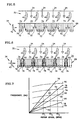
- FIG.7 graphically illustrates the relationship between an excitation force frequency 78, a natural frequency 80 of a rotor stage, and the rotational velocity of the rotor stage.
- intersections 82 shown between the excitation force frequencies 78 and the natural frequencies 80 of the rotor stage, at particular rotor stage rotational velocities (RV 1 , RV 2 , RV 3 ), are where the resonant responses are likely to occur.
- the controller 58 is programmed with empirically developed data (i.e., like that shown in FIG.7) that correlates rotor stage rotational velocity (and therefore the frequency of the excitation force) with the natural frequencies of the rotor stage 34.
- the controller 58 receives a signal representing rotor stage 34 rotational velocity from the engine speed sensor 56.
- the controller 58 sends a signal to the selectively operable valve(s) 54 to open.
- the open valve(s) 54 permits high-pressure gas bled off the compressor 14 to pass between the compressor 14 and the ports 50 disposed upstream of the rotor stage 34.
- the selectively operable valve(s) 54 is disposed in the first high-pressure line(s) 62 (see FIGS. 2 and 4), opening the valve(s) 54 permits high-pressure core gas from the compressor 14 to pass into the manifold 52 where it is distributed to each of the ports 50. If, on the other hand, the selectively operable valve(s) 54 is disposed in the second high-pressure lines 64 (see FIG.3), opening the valve(s) 54 permits high-pressure core gas from the compressor 14 already distributed in the manifold 52 to pass into each of the ports 50. In either case, the high-pressure gas 76 exiting the ports 50 (shown graphically in FIG.6) passes into the low velocity region 72 downstream of each stator vane 40.
- the high-pressure gas 76 entering the low velocity regions 72 increases the average velocity of the core gas flow 23 within the low velocity regions 72 to substantially that of the adjacent high velocity regions 70.
- Rotor blades 42 rotating past the stator vanes 40 consequently experience a substantially diminished " ⁇ F" periodic excitation force, or no periodic excitation force at all.
- the vibration and stress caused by the periodic excitation force is consequently substantially diminished or eliminated.
- the controller 58 signals the selectively operable valve(s) 54 to close and stop the flow of high-pressure gas 76 through the ports 50.
- an apparatus and method for minimizing or eliminating rotor blade vibrations, wich minimises or eliminates the cause of the vibration is provided.
Description
- This invention relates to gas turbine engine rotor assemblies in general, and to apparatus for controlling vibrations in rotor stages in particular.
- The fan, compressor, and turbine sections of a gas turbine engine typically include a plurality of stator vane and rotor stages. The stator vane stages direct air flow (referred to hereafter as "core gas flow") in a direction favorable to downstream rotor stages. Each stator vane stage includes a plurality of stator vanes extending radially between inner and outer static radial platforms. Each rotor stage includes a plurality of rotor blades extending radially out from a rotatable disk. Depending upon where the rotor stage is within the engine, the rotor stage either extracts energy from, or adds energy to, the core gas flow. The velocity of the core gas flow passing through the engine increases with the rotational velocity of the rotors within the system. A velocity curve depicting core gas flow velocities immediately downstream of a stator vane stage reflects high velocity regions disposed downstream of, and aligned with the passages between stator vanes, and low velocity regions disposed downstream of, and aligned with each stator vane. The disparity between the high and low velocity regions increases as the velocity of the core gas flow increases. The high and low velocity regions have a significant effect on rotor blades passing through the region immediately downstream of the stator vanes.
- Rotor blades typically have an aerodynamic cross-section that enable them to act as a "lifting body". The term "lifting body" refers to a normal force applied to the airfoil by air traveling past the airfoil, from leading edge to trailing edge, that "lifts" the airfoil. The normal force is a function of: (1) the velocity of the gas passing by the airfoil; (2) the angle of attack" of the airfoil relative to the direction of the gas flow; and (3) the surface area of the airfoil. The normal force is usually mathematically described as the integral of the pressure difference over the length of the airfoil. The difference in gas flow velocity exiting the stator vane stage creates differences in the normal force acting on the rotor blade.
- The changes in normal force caused by the different velocity regions are significant because of the vibration they introduce into the rotor blades individually, and the rotor stage collectively. Low velocity regions can be described as producing a normal force on each rotor blade equal to "F", and high velocity regions described as producing a normal force on each blade "F + ΔF", where ΔF represents an additional amount of normal force. A blade rotating through the regions of low and high velocity gas flow will, therefore, experience periodic pulsations of increased force "ΔF" (also referred to as a periodic excitation force). The frequency of the periodic excitation force is a function of the rotational speed of the rotor, since the number of stator vanes that create the low velocity regions is a constant. The magnitude of "ΔF" depends upon the velocity of the core gas flow.
- Vibrations in a rotor stage are never desirable, particularly when the frequency of the excitation force coincides with a natural frequency of the rotor stage; i.e., resonance. In most cases, resonance can be avoided by "tuning" the natural frequencies of the rotor stage outside the frequency of the excitation force by stiffening, adding mass, or the like. Alternatively, damping can be used to minimize the resonant response of the rotor stage. It is not always possible, however, to "tune" the natural frequencies of a rotor stage to avoid undesirable resonant responses. Nor is it always possible to effectively damp vibrations within a rotor stage.
- It would be a great advantage, therefore, to minimize or eliminate the cause of the vibration (i.e., the excitation force), rather than adapt the rotor stage to accommodate.the vibration.
- US-A-4255083 discloses a method and device for reducing the noise produced in a turbo-machine by the interaction of the blades of a ring of rotor blades and the vanes of a ring of stator vanes by the creation of a counter-noise of opposed phase. This is achieved by the injection of a fluid into the flow passage of the machine in which the blades and vanes are located.
- US-A-5275528 discloses a method of controlling gas flow in an axial flow compressor, in which the flow at least at one chosen station in the direction of flow through the compressor is sensed at a series of circumferentially spaced positions. Flow variations above a predetermined limit are evaluated to give an actuating response if the variations indicate a disturbance above a predetermined acceptable level is present. When such a disturbance is detected, high pressure flow bled from the exit end of the compressor is injected at said station to supplement the main gas flow there.
- US-A-5005353 discloses a control system that actively controls at least one troublesome mode of an unsteady motion phenomenon in turbomachinery in order to enable an increase in the operating range of the turbomachinery. The control system has a control bandwidth which is at least partly coextensive with the bandwidth of the unsteady motion phenomenon and operates by passing sensor signals related to the unsteady motion phenomenon from a sensor array in the turbomachine to a mode filter which produces a signal or signals which are related to the troublesome mode or modes.
- US-A-4199295 discloses a device for reducing the noise generated by the blades of at least one ring of rotor blades in a turbo-machine by the production of a counter-noise of opposed phase. This is achieved by injection of jets of fluid under pressure through orifices borne by the rotor located near to the periphery of the blades, and the flow of the fluid is modulated at a frequency which is a whole number multiple of the rotational frequency of the rotor shaft.
- According to a first aspect of the present invention, there is provided a fan for a gas turbine engine, comprising:
- a stator vane stage including a plurality of circumferentially distributed stator vanes;
- a rotor stage positioned downstream of and adjacent said stator vane stage;
- means for controlling vibrations in said rotor stage, said means including a plurality of ports disposed in a liner between said stator vane stage and said rotor stage and aligned with said stator vanes;
- wherein said ports are connected to a high-pressure gas source that selectively provides gas at a pressure substantially higher than a pressure of a core gas flow passing through said rotor stage; and
- wherein said high-pressure gas exits said ports and acts on said rotor stage,
- characterised in that said rotor stage rotates around an axis through core gas flow travelling substantially parallel to said axis, and in use, the core gas flow includes circumferentially distributed first regions and second regions, said first regions containing core gas flow travelling at a first velocity and said second regions containing core gas flow travelling at a second velocity, and said first velocity is substantially higher than said second velocity, and said means for controlling vibrations introduces high-pressure gas from a source of gas at a pressure substantially higher than the core gas flow into said second regions to increase the average velocity of the core gas flow within the low velocity regions to substantially that of the adjacent high velocity region so as to substantially decrease the difference in core gas flow velocity between said first and second regions.
- An advantage of the present invention is that the cause of problematic vibrations is addressed rather than resultant undesirable vibration. Rotor stages are often "tuned" to avoid undesirable resonant responses by stiffening the rotor stage or adding mass to the rotor stage. Adding mass to a blade undesirably increases the overall mass of the rotor stage and can increase stresses in the rotor disk. Rotor stages can also be damped to minimize an undesirable resonant response. Damping features almost always add to the cost of the blades, increase the blade maintenance requirements, and can limit the life of a blade. The present invention, in contrast, minimizes or eliminates forcing functions that cause vibration, and thereby eliminates the need to "tune" or damp a rotor stage.
- Another advantage of the present invention is that it can be used to minimize or eliminate problematic vibrations in integrally bladed rotors (IBR'iS). In many cases, it is exceedingly difficult to tune an IBR or provide adequate damping due to the one piece geometric configuration of the rotor For example, the blades of the IBR often cannot be machined individually to receive damping means, The present invention overcomes the damping limitations of IBM by eliminating the need to alter the rotor blades of the IBR.
- Certain preferred embodiments of the present invention will now be described by way of example only and with reference to the accompanying drawings, in which:
- FIG. 1 is a diagrammatic view of a gas turbine engine;
- FIG. 2 is a diagrammatic view of a stator vane stage and a rotor stage including a first embodiment of the present invention apparatus for controlling vibrations in a rotor stage;
- FIG. 3 is a diagrammatic view of a stator vane stage and a rotor stage including a second embodiment of the present invention apparatus for controlling vibrations in a rotor stage;
- FIG. 4 is a diagrammatic view of a stator vane stage and a rotor stage including a third embodiment which is not part of the claimed invention;
- FIG. 5 is a diagrammatic view of a stator vane stage and a rotor stage, including a velocity profile taken downstream of the stator vane stage;
- FIG.6 is a diagrammatic view of a stator vane stage and a rotor stage, including a velocity profile taken downstream of the stator vane stage. The velocity profile shown in FIG.6 shows the addition of high-pressure gas from a preferred apparatus for controlling vibrations in a rotor stage; and
- FIG.7 is a graphic illustration of the relationship between a periodic excitation force frequency and the natural frequencies of a rotor stage versus the rotational velocity of the rotor stage.
- Referring to FIG.1, a
gas turbine engine 10 includes afan 12, acompressor 14, acombustor 16, aturbine 18,apparatus 20 for controlling vibrations in a rotor stage, and anozzle 22. Air 24 (also referred to as "core gas flow") drawn into theengine 10 via thefan 12 follows a path substantially parallel to the axis of theengine 10 through thecompressor 14,combustor 16, andturbine 18 in that order. Thefan 12,compressor 14, andturbine 18, each include a plurality ofstator vane stages 32 androtor stages 34. As can be seen in FIGS. 2-4, moststator vane stages 32 include an inner 36 and an outer 38 radial platform and a plurality ofstator vanes 40 extending radially therebetween. Eachrotor stage 34 includes a plurality ofrotor blades 42 extending out from adisk 44. Therotor blades 42 may be attached to thedisk 44 via conventional attachment methods (e.g., fir tree or dovetail root - not shown) or may be integrally attached as a part of an integrally bladed rotor (IBR).Liners 46, disposed radially outside of the rotor stages 34, may include blade outer air seals (not shown), or the like, for sealing at the tip of therotor blades 42. - In the preferred embodiment, the
apparatus 20 for controlling vibrations in arotor stage 34 includes asource 48 of high-pressure gas (see FIG.1), a plurality ofports 50 for dispensing high-pressure gas upstream of therotor stage 34, a manifold 52 connecting theports 50 to thesource 48 of high-pressure gas, a selectivelyoperable valve 54 disposed between the high-pressure gas source 48 and theports 50, anengine speed sensor 56, and a programmable controller 58 (see FIG. 1 forsensor 56 and controller 58). The high-pressure gas source 48 is preferably thecompressor 14, although the exact tap position within thecompressor 14 will depend upon the pressure requirements of the application at hand; i.e., gas at a higher relative pressure can be tapped from later compressor stages and gas at a lower relative pressure can be tapped from earlier compressor stages. Eachport 50 is an orifice having a cross-sectional area chosen to produce a particular velocity of core gas flow 23 exiting theport 50, for a given pressure of gas. In an alternative embodiment, eachport 50 has a selectively adjustable cross-sectional area. In a first embodiment (FIGS. 2 and 3), theports 50 are disposed in theliner 46, between thestator vane stage 32 and therotor stage 34, aligned with the stator vanes 40. In a second embodiment (FIG.4) which is not part of the claimed invention, theports 50 are disposed in the trailingedge 60 of the stator vanes 40. Within thestator vanes 40, theports 50 are preferably positioned adjacent the outerradial platform 38, butadditional ports 50 may be disposed within or adjacent the trailingedge 60 between the inner 36 and outer 38 radial platforms. In fact, aport 50 may be disposed within the trailingedge 60 at a position radially aligned with a particular region of therotor blades 42 subject to a particular mode of vibration. One or more first high-pressure lines 62 connect the manifold 52 to thecompressor stage 34. A plurality of second high-pressure lines 64 connect the manifold 52 to theports 50. In one embodiment (FIG.2), each first high-pressure line 62 includes a selectivelyoperable valve 54. In another embodiment (FIG.3), each second high-pressure line 64 includes a selectivelyoperable valve 54. The engine speed sensor 56 (shown diagrammatically in FIG.1) is a commercially available unit, such as an electromechanical tachometer. The programmable controller 58 (shown diagrammatically in FIG. 1) is a commercially available unit that includes a central processing unit, a memory storage device, an input device, and an output device. - Referring to FIG.1, in the operation of the
engine 10, core gas flow 23 passes through thefan 12,compressor 14,combustor 16, andturbine 18 before exiting via thenozzle 22. Thefan 12 andcompressor 14 sections add energy to the core gas flow 23 by increasing the pressure of the flow 23. Thecombustor 16 adds additional energy to the core gas flow 23 by injecting fuel and combusting the mixture. Theturbine 18 extracts energy from the core gas flow 23 to power thefan 12 andcompressor 14. - Referring to FIGS. 5 and 6,
velocity profiles 68 reflecting core gas flow 23 passing through astator vane stage 32 and into the path of arotor stage 34 in thefan 12,compressor 14, orturbine 18, typically include a plurality of high 70 and low 72 velocity regions, circumferentially distributed. Thelow velocity regions 72 are disposed downstream of, and aligned with, the stator vanes 40. Thehigh velocity regions 70 are disposed downstream of, and aligned with, thepassages 74 between the stator vanes 40. Therotor blades 42 passing through the high 70 and low 72 velocity regions experience the periodic excitation force described earlier as "ΔF". The periodic excitation force is particularly problematic when it has a frequency that coincides with a natural frequency of the rotor stage 34 (including any attributable to the rotor blades 42); i.e., a resonant condition. Resonance between an excitation force and arotor stage 34 natural frequency can amplify vibrations and attendant stress levels within therotor stage 34. FIG.7 graphically illustrates the relationship between anexcitation force frequency 78, anatural frequency 80 of a rotor stage, and the rotational velocity of the rotor stage. Theintersections 82 shown between theexcitation force frequencies 78 and thenatural frequencies 80 of the rotor stage, at particular rotor stage rotational velocities (RV1, RV2, RV3), are where the resonant responses are likely to occur. - Referring to FIG.1, to avoid or minimize an undesirable resonance response, the
controller 58 is programmed with empirically developed data (i.e., like that shown in FIG.7) that correlates rotor stage rotational velocity (and therefore the frequency of the excitation force) with the natural frequencies of therotor stage 34. Thecontroller 58 receives a signal representingrotor stage 34 rotational velocity from theengine speed sensor 56. At critical junctions where excitation force frequency equals, or substantially equals, arotor stage 34 natural frequency, thecontroller 58 sends a signal to the selectively operable valve(s) 54 to open. The open valve(s) 54 permits high-pressure gas bled off thecompressor 14 to pass between thecompressor 14 and theports 50 disposed upstream of therotor stage 34. If the selectively operable valve(s) 54 is disposed in the first high-pressure line(s) 62 (see FIGS. 2 and 4), opening the valve(s) 54 permits high-pressure core gas from thecompressor 14 to pass into the manifold 52 where it is distributed to each of theports 50. If, on the other hand, the selectively operable valve(s) 54 is disposed in the second high-pressure lines 64 (see FIG.3), opening the valve(s) 54 permits high-pressure core gas from thecompressor 14 already distributed in the manifold 52 to pass into each of theports 50. In either case, the high-pressure gas 76 exiting the ports 50 (shown graphically in FIG.6) passes into thelow velocity region 72 downstream of eachstator vane 40. The high-pressure gas 76 entering thelow velocity regions 72 increases the average velocity of the core gas flow 23 within thelow velocity regions 72 to substantially that of the adjacenthigh velocity regions 70.Rotor blades 42 rotating past thestator vanes 40 consequently experience a substantially diminished "ΔF" periodic excitation force, or no periodic excitation force at all. The vibration and stress caused by the periodic excitation force is consequently substantially diminished or eliminated. When theengine speed sensor 56 indicates to thecontroller 58 that the rotational velocity of therotor stage 34, and therefore the frequency of the excitation force, has changed from the critical junction, thecontroller 58 signals the selectively operable valve(s) 54 to close and stop the flow of high-pressure gas 76 through theports 50. - Depending on the application, it may not be necessary to operate the
apparatus 20 for controlling vibrations at every instance where the natural frequency of therotor stage 34 and the frequency of the excitation force coincide. This is particularly true where the frequencies coincide at lower rotor rotational velocities where the excitation forces are relatively low in magnitude and the resonance response is tolerable. In addition, it is also possible to maintain a flow of high-pressure gas flow through theports 50 at all times, thereby eliminating the need for the selectively operable valve means 54. Depending upon the application, a constant flow through the ports may be feasible, particularly if the-cross-sectional area of each port is selectively variable. - Although this invention has been shown and described with respect to the detailed embodiments thereof, it will be understood by those skilled in the art that various changes in form and detail thereof may be made without departing from the scope of the invention as defined by the claims. As an example, the illustrated embodiments disclose the source of high-pressure gas as the compressor. Other sources of high-pressure gas may be used alternatively.
- Thus, at least in the illustrated embodiments of the present invention, there is provided an apparatus and method for minimizing or eliminating rotor blade vibrations, wich minimises or eliminates the cause of the vibration.
Claims (9)
- A fan (12) for a gas turbine engine, comprising:a stator vane stage (32) including a plurality of circumferentially distributed stator vanes (40);a rotor stage (34) positioned downstream of and adjacent said stator vane stage;means for controlling vibrations in said rotor stage, said means including a plurality of ports (50) disposed in a liner (46) between said stator vane stage and said rotor stage and aligned with said stator vanes;wherein said ports are connected to a high-pressure gas source (48) that selectively provides gas at a pressure substantially higher than a pressure of a core gas flow (23) passing through said rotor stage; andwherein said high-pressure gas exits said ports and acts on said rotor stage,characterised in that said rotor stage rotates around an axis through core gas flow (23) travelling substantially parallel to said axis, and in use, the core gas flow includes circumferentially distributed first regions (70) and second regions (72), said first regions containing core gas flow travelling at a first velocity and said second regions containing core gas flow travelling at a second velocity, and said first velocity is substantially higher than said second velocity, and said means for controlling vibrations introduces high-pressure gas (76) from a source of gas at a pressure substantially higher than the core gas flow into said second regions to increase the average velocity of the core gas flow within the low velocity regions to substantially that of the adjacent high velocity region so as to substantially decrease the difference in core gas flow velocity between said first and second regions.
- A fan (12) for a gas turbine engine as claimed in claim 1, wherein
said stator vane stage (32), includes an inner radial platform (36) and an outer radial platform (38), and
said rotor stage (34), includes a plurality of rotor blades extending radially outward from a disk; and
said liner is disposed radially outside of said rotor stage - A fan (12) for a gas turbine engine as claimed in any preceding claim, wherein said vibrations are resonant vibrations.
- A fan (12) as claimed in any preceding claim, wherein said ports are positioned upstream of and adjacent the rotor stage (34) and aligned with said second regions (72).
- A fan (12) as claimed in any preceding claim, further comprising:a selectively operable valve means (54), positioned in line between said source of high-pressure gas and said means (50) for introducing high pressure gas, wherein said selectively operable valve means can be selectively opened to permit passage of high-pressure gas from said source to said ports (50).
- A fan (12) as claimed in any of claims 1 to 4, further comprising:a manifold (52) ;at least one first line (62) for connecting said manifold to said source of high-pressure gas; anda plurality of second lines (64), connecting said plurality of ports (50) to said manifold; andwherein said manifold distributes said high-pressure gas to said ports (50).
- A fan (12) as claimed in claim 6, further comprising:a selectively operable valve means (54), disposed in each said first line (62), wherein said selectively operable valve means can be selectively opened to permit passage of high-pressure gas from said source to said ports (50).
- A fan (12) as claimed in claim 6, further comprising:a selectively operable valve means (54), disposed in each said second line (64), wherein said selectively operable valve means can be selectively opened to permit passage of high-pressure gas from said source to said ports (50).
- A fan (12) as claimed in claims 5, 6 or 7, further comprising:a programmable controller (58) ;a velocity sensor (56) for sensing the rotational velocity of the rotor stage (34);wherein said velocity sensor sends a signal to said controller indicating the rotational velocity of the rotor stage, and said controller causes said selectively operable valve means (54) to open and close at certain rotor stage rotational velocities.
Applications Claiming Priority (3)
| Application Number | Priority Date | Filing Date | Title |
|---|---|---|---|
| US920493 | 1997-08-29 | ||
| US08/920,493 US6055805A (en) | 1997-08-29 | 1997-08-29 | Active rotor stage vibration control |
| EP98306925A EP0899427B1 (en) | 1997-08-29 | 1998-08-28 | Active turbomachine rotor stage vibration control |
Related Parent Applications (1)
| Application Number | Title | Priority Date | Filing Date |
|---|---|---|---|
| EP98306925A Division EP0899427B1 (en) | 1997-08-29 | 1998-08-28 | Active turbomachine rotor stage vibration control |
Publications (3)
| Publication Number | Publication Date |
|---|---|
| EP1353039A2 EP1353039A2 (en) | 2003-10-15 |
| EP1353039A3 EP1353039A3 (en) | 2004-05-06 |
| EP1353039B1 true EP1353039B1 (en) | 2006-10-11 |
Family
ID=25443842
Family Applications (2)
| Application Number | Title | Priority Date | Filing Date |
|---|---|---|---|
| EP03013346A Expired - Lifetime EP1353039B1 (en) | 1997-08-29 | 1998-08-28 | Fan with active rotor stage vibration control |
| EP98306925A Expired - Lifetime EP0899427B1 (en) | 1997-08-29 | 1998-08-28 | Active turbomachine rotor stage vibration control |
Family Applications After (1)
| Application Number | Title | Priority Date | Filing Date |
|---|---|---|---|
| EP98306925A Expired - Lifetime EP0899427B1 (en) | 1997-08-29 | 1998-08-28 | Active turbomachine rotor stage vibration control |
Country Status (5)
| Country | Link |
|---|---|
| US (2) | US6055805A (en) |
| EP (2) | EP1353039B1 (en) |
| JP (1) | JPH11141307A (en) |
| KR (1) | KR100539037B1 (en) |
| DE (2) | DE69825825T2 (en) |
Families Citing this family (49)
| Publication number | Priority date | Publication date | Assignee | Title |
|---|---|---|---|---|
| US6202403B1 (en) * | 1998-12-22 | 2001-03-20 | General Electric Company | Core compartment valve cooling valve scheduling |
| FR2814197B1 (en) * | 2000-09-21 | 2003-01-10 | Snecma Moteurs | METHOD AND DEVICE FOR MITIGATION OF ROTOR / STATOR INTERACTION SOUNDS IN A TURBOMACHINE |
| US6409469B1 (en) * | 2000-11-21 | 2002-06-25 | Pratt & Whitney Canada Corp. | Fan-stator interaction tone reduction |
| US7631483B2 (en) * | 2003-09-22 | 2009-12-15 | General Electric Company | Method and system for reduction of jet engine noise |
| GB2407142B (en) * | 2003-10-15 | 2006-03-01 | Rolls Royce Plc | An arrangement for bleeding the boundary layer from an aircraft engine |
| JP2005226584A (en) * | 2004-02-13 | 2005-08-25 | Honda Motor Co Ltd | Compressor and gas turbine engine |
| DE102004030597A1 (en) * | 2004-06-24 | 2006-01-26 | Rolls-Royce Deutschland Ltd & Co Kg | Turbomachine with external wheel jet generation at the stator |
| DE102004054752A1 (en) * | 2004-11-12 | 2006-05-18 | Rolls-Royce Deutschland Ltd & Co Kg | Blade of a flow machine with extended edge profile depth |
| DE102005052466A1 (en) * | 2005-11-03 | 2007-05-10 | Mtu Aero Engines Gmbh | Multi-stage compressor for a gas turbine with blow-off openings and injection openings for stabilizing the compressor flow |
| US7617670B2 (en) * | 2006-03-31 | 2009-11-17 | Lockheed Martin Corporation | Flow control redistribution to mitigate high cycle fatigue |
| US20070245708A1 (en) * | 2006-04-20 | 2007-10-25 | United Technologies Corporation | High cycle fatigue management for gas turbine engines |
| US7797944B2 (en) * | 2006-10-20 | 2010-09-21 | United Technologies Corporation | Gas turbine engine having slim-line nacelle |
| US7870721B2 (en) * | 2006-11-10 | 2011-01-18 | United Technologies Corporation | Gas turbine engine providing simulated boundary layer thickness increase |
| US7811050B2 (en) * | 2006-12-28 | 2010-10-12 | General Electric Company | Operating line control of a compression system with flow recirculation |
| US8408491B2 (en) * | 2007-04-24 | 2013-04-02 | United Technologies Corporation | Nacelle assembly having inlet airfoil for a gas turbine engine |
| DE102007026455A1 (en) | 2007-06-05 | 2008-12-11 | Rolls-Royce Deutschland Ltd & Co Kg | Jet engine with compressor air circulation and method of operating the same |
| US8082726B2 (en) * | 2007-06-26 | 2011-12-27 | United Technologies Corporation | Tangential anti-swirl air supply |
| US8402739B2 (en) * | 2007-06-28 | 2013-03-26 | United Technologies Corporation | Variable shape inlet section for a nacelle assembly of a gas turbine engine |
| US8371806B2 (en) * | 2007-10-03 | 2013-02-12 | United Technologies Corporation | Gas turbine engine having core auxiliary duct passage |
| US8240120B2 (en) * | 2007-10-25 | 2012-08-14 | United Technologies Corporation | Vibration management for gas turbine engines |
| US9004399B2 (en) | 2007-11-13 | 2015-04-14 | United Technologies Corporation | Nacelle flow assembly |
| US8186942B2 (en) * | 2007-12-14 | 2012-05-29 | United Technologies Corporation | Nacelle assembly with turbulators |
| US8192147B2 (en) * | 2007-12-14 | 2012-06-05 | United Technologies Corporation | Nacelle assembly having inlet bleed |
| DE102008016800A1 (en) * | 2008-04-02 | 2009-10-08 | Mtu Aero Engines Gmbh | Gas turbine compressor |
| FR2931906B1 (en) * | 2008-05-30 | 2017-06-02 | Snecma | TURBOMACHINE COMPRESSOR WITH AIR INJECTION SYSTEM. |
| DE102008052409A1 (en) | 2008-10-21 | 2010-04-22 | Rolls-Royce Deutschland Ltd & Co Kg | Turbomachine with near-suction edge energization |
| US8591166B2 (en) * | 2008-12-31 | 2013-11-26 | Rolls-Royce North American Technologies, Inc. | Axial compressor vane |
| DE102009032549A1 (en) * | 2009-07-10 | 2011-01-13 | Mtu Aero Engines Gmbh | Method for reducing vibration amplitudes |
| US20110250046A1 (en) * | 2010-04-07 | 2011-10-13 | Honeywell International Inc. | Turbofan engine performance recovery system and method |
| US8105039B1 (en) | 2011-04-01 | 2012-01-31 | United Technologies Corp. | Airfoil tip shroud damper |
| WO2013102098A1 (en) * | 2011-12-29 | 2013-07-04 | Rolls-Royce North American Technologies, Inc. | Vavle for gas turbine engine |
| US8640820B2 (en) * | 2012-01-11 | 2014-02-04 | Polytechnic Institute Of New York University | High-speed jet noise reduction via fluidic injection |
| US10107191B2 (en) * | 2012-02-29 | 2018-10-23 | United Technologies Corporation | Geared gas turbine engine with reduced fan noise |
| US9017033B2 (en) | 2012-06-07 | 2015-04-28 | United Technologies Corporation | Fan blade platform |
| US20150252679A1 (en) * | 2012-10-01 | 2015-09-10 | United Technologies Corporation | Static guide vane with internal hollow channels |
| US20160258440A1 (en) * | 2015-03-02 | 2016-09-08 | Rolls-Royce Corporation | Gas turbine engine with airfoil dampening system |
| FR3034145B1 (en) * | 2015-03-26 | 2017-04-07 | Snecma | COMPRESSOR FLOOR |
| EP3296573A1 (en) * | 2016-09-20 | 2018-03-21 | Siemens Aktiengesellschaft | A technique for controlling rotating stall in compressor for a gas turbine engine |
| WO2018147837A1 (en) * | 2017-02-08 | 2018-08-16 | Siemens Aktiengesellschaft | Method for minimizing forces acting on turbine blades in specific frequency ranges |
| US10775269B2 (en) * | 2017-02-08 | 2020-09-15 | Raytheon Technologies Corporation | Blade health inspection using an excitation actuator and vibration sensor |
| EP3477120A1 (en) * | 2017-10-26 | 2019-05-01 | Siemens Aktiengesellschaft | Gas turbine engine control method and system |
| JP6916755B2 (en) * | 2018-03-09 | 2021-08-11 | 三菱重工業株式会社 | Rotating machine |
| FR3079552B1 (en) * | 2018-03-29 | 2021-06-04 | Safran Aircraft Engines | TURBOMACHINE WITH AT LEAST ONE UPSTREAM VANE INCLUDING A BLOWING PORTION TO LIMIT THE RESONANCE OF A DOWNSTREAM VANE |
| US20200072062A1 (en) * | 2018-08-31 | 2020-03-05 | General Electric Company | System and Method for Airfoil Vibration Control |
| CA3073417A1 (en) | 2019-04-18 | 2020-10-18 | Pratt & Whitney Canada Corp. | Fan blade ice protection using hot air |
| US11118457B2 (en) * | 2019-10-21 | 2021-09-14 | Pratt & Whitney Canada Corp. | Method for fan blade heating using coanda effect |
| US11828237B2 (en) | 2020-04-28 | 2023-11-28 | General Electric Company | Methods and apparatus to control air flow separation of an engine |
| US11333079B2 (en) * | 2020-04-28 | 2022-05-17 | General Electric Company | Methods and apparatus to detect air flow separation of an engine |
| US11085303B1 (en) * | 2020-06-16 | 2021-08-10 | General Electric Company | Pressurized damping fluid injection for damping turbine blade vibration |
Family Cites Families (10)
| Publication number | Priority date | Publication date | Assignee | Title |
|---|---|---|---|---|
| US2958456A (en) * | 1954-10-06 | 1960-11-01 | Power Jets Res & Dev Ltd | Multi-stage aerofoil-bladed compressors |
| US3572960A (en) * | 1969-01-02 | 1971-03-30 | Gen Electric | Reduction of sound in gas turbine engines |
| BE755567A (en) * | 1969-12-01 | 1971-02-15 | Gen Electric | FIXED VANE STRUCTURE, FOR GAS TURBINE ENGINE AND ASSOCIATED TEMPERATURE ADJUSTMENT ARRANGEMENT |
| FR2370170A1 (en) * | 1976-11-05 | 1978-06-02 | Snecma | METHOD AND DEVICE FOR REDUCING TURBOMACHINE NOISE |
| FR2370171A1 (en) * | 1976-11-05 | 1978-06-02 | Snecma | METHOD AND DEVICE FOR REDUCING TURBOMACHINE NOISE |
| GB2125111B (en) * | 1982-03-23 | 1985-06-05 | Rolls Royce | Shroud assembly for a gas turbine engine |
| US5082421A (en) * | 1986-04-28 | 1992-01-21 | Rolls-Royce Plc | Active control of unsteady motion phenomena in turbomachinery |
| US5275528A (en) * | 1990-08-28 | 1994-01-04 | Rolls-Royce Plc | Flow control method and means |
| AU3277295A (en) * | 1994-07-28 | 1996-02-22 | Boeing Company, The | Active control of tone noise in engine ducts |
| US5584651A (en) * | 1994-10-31 | 1996-12-17 | General Electric Company | Cooled shroud |
-
1997
- 1997-08-29 US US08/920,493 patent/US6055805A/en not_active Expired - Lifetime
-
1998
- 1998-08-28 EP EP03013346A patent/EP1353039B1/en not_active Expired - Lifetime
- 1998-08-28 KR KR1019980035194A patent/KR100539037B1/en not_active IP Right Cessation
- 1998-08-28 DE DE69825825T patent/DE69825825T2/en not_active Expired - Lifetime
- 1998-08-28 DE DE69836154T patent/DE69836154T2/en not_active Expired - Lifetime
- 1998-08-28 EP EP98306925A patent/EP0899427B1/en not_active Expired - Lifetime
- 1998-08-31 JP JP10260997A patent/JPH11141307A/en active Pending
-
1999
- 1999-11-24 US US09/448,262 patent/US6125626A/en not_active Expired - Lifetime
Also Published As
| Publication number | Publication date |
|---|---|
| DE69825825T2 (en) | 2005-09-01 |
| US6125626A (en) | 2000-10-03 |
| EP0899427A2 (en) | 1999-03-03 |
| DE69836154T2 (en) | 2007-02-01 |
| EP1353039A3 (en) | 2004-05-06 |
| DE69825825D1 (en) | 2004-09-30 |
| US6055805A (en) | 2000-05-02 |
| EP1353039A2 (en) | 2003-10-15 |
| KR100539037B1 (en) | 2006-02-28 |
| JPH11141307A (en) | 1999-05-25 |
| KR19990023997A (en) | 1999-03-25 |
| EP0899427B1 (en) | 2004-08-25 |
| DE69836154D1 (en) | 2006-11-23 |
| EP0899427A3 (en) | 2000-07-05 |
Similar Documents
| Publication | Publication Date | Title |
|---|---|---|
| EP1353039B1 (en) | Fan with active rotor stage vibration control | |
| US6546734B2 (en) | Process and device for attenuating the noise made in a turbomachine by rotor/stator interaction | |
| US5658125A (en) | Magnetic bearings as actuation for active compressor stability control | |
| US5005353A (en) | Active control of unsteady motion phenomena in turbomachinery | |
| Day | Active suppression of rotating stall and surge in axial compressors | |
| US4967550A (en) | Active control of unsteady motion phenomena in turbomachinery | |
| EP2820270B1 (en) | Geared gas turbine engine with reduced fan noise | |
| EP1252424B1 (en) | Method of operating a variable cycle gas turbine engine | |
| JP5550563B2 (en) | How to operate a compressor | |
| US6244817B1 (en) | Method and apparatus for a fan noise controller | |
| US5230603A (en) | Control of flow instabilities in turbomachines | |
| EP3179071A1 (en) | Geared gas turbine engine with reduced fan noise | |
| EP3115577A1 (en) | Low noise turbine for geared turbofan engine | |
| US5167486A (en) | Turbo-machine stage having reduced secondary losses | |
| EP3940199A1 (en) | System and method for air injection passageway integration and optimization in turbomachinery | |
| EP4172479A1 (en) | Gas turbine air bleed arrangement with an inlet having a non uniform profile | |
| EP3613955B1 (en) | Airfoil deicing system | |
| JPH10306732A (en) | Stator assembly for gas turbine engine passage and operating medium gas passage forming method | |
| EP3604741B1 (en) | Turbomachinery transition duct for wide bypass ratio ranges | |
| EP3575561B1 (en) | A turbofan engine and a method of controlling loads on a speed reduction device | |
| EP3553283B1 (en) | Gas turbine engine component for acoustic attenuation | |
| JPH0450401Y2 (en) | ||
| GB2253443A (en) | Gas turbine nozzle guide vane arrangement | |
| US20230323834A1 (en) | Gas turbine engine with a compressed airflow injection assembly | |
| EP3916204B1 (en) | Speed-controlled conditioning valve for high pressure compressor |
Legal Events
| Date | Code | Title | Description |
|---|---|---|---|
| PUAI | Public reference made under article 153(3) epc to a published international application that has entered the european phase |
Free format text: ORIGINAL CODE: 0009012 |
|
| AC | Divisional application: reference to earlier application |
Ref document number: 0899427 Country of ref document: EP Kind code of ref document: P |
|
| AK | Designated contracting states |
Kind code of ref document: A2 Designated state(s): DE FR GB |
|
| PUAL | Search report despatched |
Free format text: ORIGINAL CODE: 0009013 |
|
| AK | Designated contracting states |
Kind code of ref document: A3 Designated state(s): DE FR GB |
|
| 17P | Request for examination filed |
Effective date: 20041025 |
|
| AKX | Designation fees paid |
Designated state(s): DE FR GB |
|
| 17Q | First examination report despatched |
Effective date: 20050413 |
|
| GRAP | Despatch of communication of intention to grant a patent |
Free format text: ORIGINAL CODE: EPIDOSNIGR1 |
|
| GRAS | Grant fee paid |
Free format text: ORIGINAL CODE: EPIDOSNIGR3 |
|
| GRAA | (expected) grant |
Free format text: ORIGINAL CODE: 0009210 |
|
| AC | Divisional application: reference to earlier application |
Ref document number: 0899427 Country of ref document: EP Kind code of ref document: P |
|
| AK | Designated contracting states |
Kind code of ref document: B1 Designated state(s): DE FR GB |
|
| REG | Reference to a national code |
Ref country code: GB Ref legal event code: FG4D |
|
| REF | Corresponds to: |
Ref document number: 69836154 Country of ref document: DE Date of ref document: 20061123 Kind code of ref document: P |
|
| ET | Fr: translation filed | ||
| PLBE | No opposition filed within time limit |
Free format text: ORIGINAL CODE: 0009261 |
|
| STAA | Information on the status of an ep patent application or granted ep patent |
Free format text: STATUS: NO OPPOSITION FILED WITHIN TIME LIMIT |
|
| 26N | No opposition filed |
Effective date: 20070712 |
|
| PGFP | Annual fee paid to national office [announced via postgrant information from national office to epo] |
Ref country code: FR Payment date: 20090806 Year of fee payment: 12 |
|
| REG | Reference to a national code |
Ref country code: FR Ref legal event code: ST Effective date: 20110502 |
|
| PG25 | Lapsed in a contracting state [announced via postgrant information from national office to epo] |
Ref country code: FR Free format text: LAPSE BECAUSE OF NON-PAYMENT OF DUE FEES Effective date: 20100831 |
|
| PGFP | Annual fee paid to national office [announced via postgrant information from national office to epo] |
Ref country code: DE Payment date: 20150722 Year of fee payment: 18 Ref country code: GB Payment date: 20150724 Year of fee payment: 18 |
|
| REG | Reference to a national code |
Ref country code: DE Ref legal event code: R119 Ref document number: 69836154 Country of ref document: DE |
|
| GBPC | Gb: european patent ceased through non-payment of renewal fee |
Effective date: 20160828 |
|
| PG25 | Lapsed in a contracting state [announced via postgrant information from national office to epo] |
Ref country code: DE Free format text: LAPSE BECAUSE OF NON-PAYMENT OF DUE FEES Effective date: 20170301 Ref country code: GB Free format text: LAPSE BECAUSE OF NON-PAYMENT OF DUE FEES Effective date: 20160828 |