EP1351522A2 - Scanning type display optical system, scanning image display apparatus, and image display system - Google Patents
Scanning type display optical system, scanning image display apparatus, and image display system Download PDFInfo
- Publication number
- EP1351522A2 EP1351522A2 EP03251708A EP03251708A EP1351522A2 EP 1351522 A2 EP1351522 A2 EP 1351522A2 EP 03251708 A EP03251708 A EP 03251708A EP 03251708 A EP03251708 A EP 03251708A EP 1351522 A2 EP1351522 A2 EP 1351522A2
- Authority
- EP
- European Patent Office
- Prior art keywords
- light
- optical system
- diffraction
- scanning type
- scanning
- Prior art date
- Legal status (The legal status is an assumption and is not a legal conclusion. Google has not performed a legal analysis and makes no representation as to the accuracy of the status listed.)
- Withdrawn
Links
Images






Classifications
-
- G—PHYSICS
- G03—PHOTOGRAPHY; CINEMATOGRAPHY; ANALOGOUS TECHNIQUES USING WAVES OTHER THAN OPTICAL WAVES; ELECTROGRAPHY; HOLOGRAPHY
- G03B—APPARATUS OR ARRANGEMENTS FOR TAKING PHOTOGRAPHS OR FOR PROJECTING OR VIEWING THEM; APPARATUS OR ARRANGEMENTS EMPLOYING ANALOGOUS TECHNIQUES USING WAVES OTHER THAN OPTICAL WAVES; ACCESSORIES THEREFOR
- G03B33/00—Colour photography, other than mere exposure or projection of a colour film
- G03B33/06—Colour photography, other than mere exposure or projection of a colour film by additive-colour projection apparatus
-
- G—PHYSICS
- G02—OPTICS
- G02B—OPTICAL ELEMENTS, SYSTEMS OR APPARATUS
- G02B26/00—Optical devices or arrangements for the control of light using movable or deformable optical elements
- G02B26/08—Optical devices or arrangements for the control of light using movable or deformable optical elements for controlling the direction of light
- G02B26/10—Scanning systems
- G02B26/101—Scanning systems with both horizontal and vertical deflecting means, e.g. raster or XY scanners
-
- G—PHYSICS
- G02—OPTICS
- G02B—OPTICAL ELEMENTS, SYSTEMS OR APPARATUS
- G02B27/00—Optical systems or apparatus not provided for by any of the groups G02B1/00 - G02B26/00, G02B30/00
- G02B27/10—Beam splitting or combining systems
- G02B27/1006—Beam splitting or combining systems for splitting or combining different wavelengths
- G02B27/102—Beam splitting or combining systems for splitting or combining different wavelengths for generating a colour image from monochromatic image signal sources
- G02B27/104—Beam splitting or combining systems for splitting or combining different wavelengths for generating a colour image from monochromatic image signal sources for use with scanning systems
-
- G—PHYSICS
- G02—OPTICS
- G02B—OPTICAL ELEMENTS, SYSTEMS OR APPARATUS
- G02B27/00—Optical systems or apparatus not provided for by any of the groups G02B1/00 - G02B26/00, G02B30/00
- G02B27/10—Beam splitting or combining systems
- G02B27/1086—Beam splitting or combining systems operating by diffraction only
-
- G—PHYSICS
- G03—PHOTOGRAPHY; CINEMATOGRAPHY; ANALOGOUS TECHNIQUES USING WAVES OTHER THAN OPTICAL WAVES; ELECTROGRAPHY; HOLOGRAPHY
- G03B—APPARATUS OR ARRANGEMENTS FOR TAKING PHOTOGRAPHS OR FOR PROJECTING OR VIEWING THEM; APPARATUS OR ARRANGEMENTS EMPLOYING ANALOGOUS TECHNIQUES USING WAVES OTHER THAN OPTICAL WAVES; ACCESSORIES THEREFOR
- G03B21/00—Projectors or projection-type viewers; Accessories therefor
- G03B21/14—Details
- G03B21/20—Lamp housings
- G03B21/2006—Lamp housings characterised by the light source
- G03B21/2013—Plural light sources
-
- H—ELECTRICITY
- H04—ELECTRIC COMMUNICATION TECHNIQUE
- H04N—PICTORIAL COMMUNICATION, e.g. TELEVISION
- H04N9/00—Details of colour television systems
- H04N9/12—Picture reproducers
- H04N9/31—Projection devices for colour picture display, e.g. using electronic spatial light modulators [ESLM]
- H04N9/3129—Projection devices for colour picture display, e.g. using electronic spatial light modulators [ESLM] scanning a light beam on the display screen
Definitions
- the present invention relates to a scanning type display optical system displaying an image by scanning light.
- each apparatus modulates light by a two-dimensional light modulation device such as a liquid crystal panel, and enlarges and projects the modulated light transmitted through or reflected by the light modulation device on a screen through an optical system, are proposed.
- This scanning type image display apparatus can display an image with high color reproducibility in high resolution by using light sources with high directivity such as lasers and selecting appropriate wavelength regions of light beams emitted from the light sources.
- Fig. 13 shows the structure of the scanning image type display apparatus proposed in the above-described Japanese Patent Laid-Open No. 1995-168123.
- light beams 412, 422, and 432 that have three different wavelength regions and are emitted from rare gas laser sources 410, 420, and 430 are modulated respectively by modulators 414, 424, and 434, and are combined by dichroic mirrors 416, and 426.
- a combined beam 440 is scanned on a screen 454 in a two-dimensional direction by optical scanning mirrors 444 and 446, and forms a color image on the screen 454.
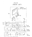
- Fig. 14 shows the structure of an apparatus proposed in the above-described Japanese Patent Laid-Open No. 1990-25831.
- reference numeral 510 shows a He-Ne laser light source
- reference numeral 520 shows an Ar laser light source.
- a light beam in a red system from the He-Ne laser source 510 is modulated by an optical modulator 513.
- a light beam from the Ar laser light source 520 is split into a green component and a blue component by a beam splitting element 522. And the green and blue components are modulated respectively by different optical modulators 525 and 533.
- the scanning optical system 504 scans the combined beam two-dimensionally by optical scanning mirrors 542 and 545, and displays a color image on a screen 547.
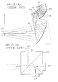
- Figs. 15(A) and 15(B) show the structure of an optical system that is applied to a head-mounted image display apparatus, proposed in Japanese Patent Laid-Open No. 2001-194617.
- Fig. 15(A) shows the outline of the optical system, where a light flux from a light source 614 is reflected on a reflecting surface 628 of a prismatic optical system 632 and enters into a scanning mirror 613 after passing through a surface 624 of the prismatic optical system.
- the scanning mirror 613 scans the incident light.
- the scanned light enters into the prismatic optical system 632 again, and is reflected on a plurality of surfaces to be emitted from a surface 621 to observer's pupils 611.
- a dichroic prism 614' that is a color combining element shown in Fig. 15(B) is actually arranged. Owing to this, three colors of light from light sources 651R, 651G, and 651B corresponding to red, green, and blue are combined by the dichroic prism 614', and the combined light is emitted toward the prismatic optical system 632.
- each color combining system in the optical systems proposed in the above-described Japanese Patent Laid-Open No. 1995-168123 and Japanese Patent Laid-Open No. 1990-25831 is formed by combining and arranging a plurality of dichroic mirrors, an optical path route becomes large so that the entire optical system is enlarged.
- structure of the color combining system becomes complex since there are a lot of parts.
- the present invention aims to provide a scanning type display optical system that can reduce the number of parts and can achieve miniaturization.
- the scanning type display optical system includes a plurality of light sources emitting light having wavelength regions mutually different, a light combining element combining the light from the plurality of light sources, and a scanning optical system scanning the light, combined by the light combining element on a scan surface. Then, it is made that the light combining element is a diffraction optical element.
- Fig. 1 shows the structure of a scanning type image display apparatus that comprises a scanning type display optical system that is Embodiment 1 of the present invention.
- This scanning type image display optical system comprises a light source optical system 101 combining a plurality of color beams of light and outputting the combined beam, a projection optical system 102 condensing the beam from the light source optical system 101, and a scanning optical system 103 having a horizontal scanning mirror 103a and a vertical scanning mirror 103b that scan the beam (condensed point), condensed by the projection optical system 102, in the horizontal direction and the vertical direction respectively on a screen 105.
- the light source optical system 101 has light sources 106a, 106b, and 106c that emit three color light fluxes respectively.
- the light sources 106a, 106b, and 106c are connected to light source driving circuits 111a, 111b, and 111c respectively, and the light source driving circuits 111a, 111b, and 111c are connected to a control circuit 112.
- the control circuit 112 is also connected to actuators 103c and 103d that drive the horizontal scanning mirror 103a and vertical scanning mirror 103b respectively.
- the control circuit 112 outputs modulating signals to the light source driving circuits 111a, 111b, and 111c according to an image signal inputted from an image supplying apparatus 104 such as a personal computer, a television set, a VTR, or a DVD player. Then, the light source driving circuits 111a, 111b, and 111c drive the light sources 106a, 106b, and 106c according to the inputted modulating signals so as to modulate the light emitted from the light source.
- An image display system is constituted by the scanning type image display apparatus and image supplying apparatus 104.
- the three colors light fluxes emitted from the light sources 106a, 106b, and 106c become beams of light by passing through a collimating optical system 107 described later, and are combined into one beam by passing through a color combining diffraction optical element 110. This combined beam is condensed by the projection optical system 102 to enter into the horizontal scanning mirror 103a.
- the horizontal scanning mirror 103a is driven by the actuator 103c so as to oscillate in the horizontal direction at high speed, and the beam reflected by the horizontal scanning mirror 103a enters into the vertical scanning mirror 103b.
- the vertical scanning mirror 103b is driven by the actuator 103d so as to oscillate in the vertical direction at high speed. Owing to this, the beam reflected by the vertical scanning mirror 103b is scanned on the screen 105 in the horizontal and vertical directions, and an image is displayed on the screen 105.
- Three light sources 106a, 106b, and 106c are semiconductor light sources such as laser diodes, or light emitting diodes (inorganic semiconductor light sources or organic semiconductor light sources) that generate light in different wavelength regions such as a red wavelength region (R) of 600 to 670 nm, a green wavelength region (G) of 500 to 570 nm, and a blue wavelength region (B) of 420 to 490 nm, and can directly modulate light emitted therefrom respectively.
- R red wavelength region
- G green wavelength region
- B blue wavelength region
- light emitting devices that emit light fluxes having the above-described wavelength regions, each of which uses a second order harmonic generator (SHG), may be used as the light sources 106a, 106b, and 106c.
- SHG second order harmonic generator
- the light sources 106a, 106b, and 106c are arranged on a plane approximately orthogonal to a main optical axis 116.
- each of the three color light fluxes emitted from the light sources 106a, 106b, and 106c has divergence. Nevertheless, each of the light fluxes (113r, 113g, and 113b) emitted from the respective light sources 106a, 106b, and 106c is made to be approximately parallel light flux (beam of light: 113r', 113g', 113b') by the collimating optical system 107 comprising the collimating lenses 108a, 108b and 108c as first optical elements arranged independently on three color optical paths respectively, and a second optical element 109 arranged commonly to the three color optical paths.
- the beams 113r', 113g', and 113b' enter into the approximately same regions on the color combining diffraction optical element 110.
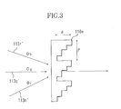
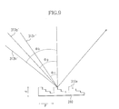
- the respective beams 113r, 113g, and 113b have incident angles named ⁇ r, ⁇ g, and ⁇ b for the color combining diffraction optical element 110 as shown in Figs. 2 and 3.
- a diffraction grating 110a constituted by a plurality of step-wise grating portions 110a with height d which are arranged in a pitch (grating period) P, is formed.
- the diffraction grating 110a of this embodiment has the structure that a diffraction order where a diffraction efficiency of an incident light becomes maximum varies according to a wavelength of the incident light.
- the grating pitch (grating period) P is determined so that the beams 113r', 113g' and 113b' incident on the color combining diffraction optical element 110 at ⁇ r, ⁇ g, and ⁇ b that are shown in Fig. 3 may have one optical path after being emitted.
- the diffraction grating 110a has a minute shape, the large volume of a dichroic prism is not needed. Therefore, it is possible to miniaturize the color combining diffraction optical element 110 itself. Thus, it is also possible to miniaturize the light source optical system 101.
- the light source optical system 101 is divided into the collimating optical system 107 and color combining diffraction optical element 110 in this embodiment, it is possible to achieve the further miniaturization of the light source optical system 101 by integrating the collimating optical system 107, and color combining diffraction optical element 110.
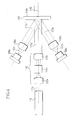
- Fig. 4 shows a modified example of the light source optical system 101 in the above-described Embodiment 1. Since the other structure of the scanning type image display apparatus is similar to the structure shown in Fig. 1, its explanation will be omitted.
- the three light sources 106a, 106b, and 106c are semiconductor light sources which can directly modulate light emitting therefrom, is described in the scanning type image display apparatus shown in Fig. 1. Nevertheless, in this modified example, two out of three light sources, the light sources 106a and 106c can directly modulate light emitting therefrom, and one, the light source 114 is a light emitting device that light emitted therefrom is modulated by an external modulation optical system 115.
- the light sources 106a and 106c are semiconductor light sources that emit light fluxes 117r and 117b in a red wavelength region (R) and a blue wavelength region (B) respectively and can directly modulate the light fluxes 117r and 117b.
- the light fluxes (beams) enter into the color combining diffraction optical element 110 after being collimated by the collimating lenses 108a and 108c respectively.
- the light source 114 is a rare-gas laser source or a diode-pumped solid state laser source.
- the light flux (beam) 117g emitted from the light source 114 enters into the modulation optical system 115.
- the modulation optical system 115 is constituted by condenser lenses 115a and 115c, and an acousto-optic modulator 115b.
- the acousto-optic modulator 115b is connected to a driving circuit not shown, and modulates and emits the beam 117g.
- the collimating optical system 107 is constituted by the collimating lenses 108a to 108c and the second optical element 109 in this embodiment, the present invention is not limited to this.
- structure can be performed so that each light flux may enter into the color combining diffraction optical element 110 in approximately parallel light flux, it is possible to obtain similar results.
- it is possible to achieve miniaturization by having such structure that the collimating lens 108a to 108c and the second optical element 109 are integrated to play both actions.
- the scanning type image display apparatus scanning type display optical system
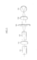
- the present invention is not limited to this. It is also possible to have such structure that the size of the screen 105 is made small and an image is displayed by scanning light on the screen 105 similarly to this embodiment as shown in FIG. 5, and the image formed by the light scan is observed through an eyepiece optical system 119 by observer's eye 120. When being constituted in this manner, the image display optical system is consequently constituted so that light scanned on the screen 105 is scanned on the retina in the eye 120.
- This structure can apply to a head-mounted display apparatus, an electric view finder optical system etc.
- a grating pitch of the color combining diffraction optical element is set as 20 ⁇ m is described in Embodiment 1, the present invention is not limited to this. Since a splitting angle of each diffraction order light becomes large when a grating pitch of a diffraction optical element is lessened, it becomes possible to avoid mechanical interference of light sources, and hence, it is possible to further miniaturize the entire apparatus.
- Fig. 11 shows the diffraction efficiency at the time when a grating pitch P is made to be 10 ⁇ m. In the case of 10 ⁇ m also, the diffraction efficiency in each wavelength region corresponding to a diffraction order shows comparatively high values. Nevertheless, it can be seen that the polarization dependence appears in the diffraction efficiency a little.
- Fig. 6 shows a light source optical system 201 in a scanning type image display apparatus that is Embodiment 2 of the present invention. Since the other components among those of the scanning type image display apparatus are similar to those in Embodiment 1, their explanation will be omitted.
- Light sources 206a, 206b, and 206c are connected to a control circuit (refer to reference numeral 112 in Fig. 1) that drive these light sources 206a, 206b, and 206c respectively on the basis of an image signal inputted from the image supplying apparatus 104 shown in Fig. 1.
- the light sources 206a, 206b, and 206c according to this embodiment are light sources, which emit polarized light fluxes , such as semiconductor laser diodes directly modulating an emitting light therefrom on the basis of the image signal. Arrows and double circles in Fig. 6 show polarized directions of the light fluxes from respective light sources.
- the light sources 206a, 206b, and 206c emit light fluxes with wavelength regions corresponding to red, green, and blue respectively. These light fluxes having divergence are collimated respectively by collimating lenses 208a, 208b, and 208c and are combined by a color combining diffraction optical element 210.
- a diffraction grating 210a constituted by a plurality of grating portions with a pitch P and height d is formed on the outgoing surface side (the right side in the figure) of the color combining diffraction optical element 210.
- the pitch P is determined so that the three color light fluxes(beams of light) may be combined in one when the three color light fluxes (color light beams) having different incident angles are emitted.
- the diffraction grating 210a in this embodiment uses structural birefringence. That is, this diffraction grating 210a does not exert a diffraction effect since acting as a zero-th order grating for a light flux (light flux from the light source 206b) having a polarized direction perpendicular (direction approximately parallel to a direction where the diffraction grating 210a is extended) to this paper surface of Fig. 7.
- this diffraction grating 210a is designed so that diffraction efficiencies of the plus and minus first order ( ⁇ 1) diffracted light may become high for light fluxes (light fluxes from the light sources 206a and 206c) having a polarized direction parallel (approximately orthogonal to the direction where the diffraction grating 210a is extended) to this paper surface.
- this embodiment it is possible in this embodiment to perform color composition (combination) by providing the light source 206b emitting the light flux that has the polarized direction where the diffraction effect is not exerted (of acting as the zero-th order grating) and the light sources 206a and 206c emitting the light fluxes with the polarized directions where the diffraction effect that makes them the plus and minus first order diffracted light is exerted, and using the polarization selectivity and diffraction effect of the color combining diffraction optical element 210.
- color composition (combination) is performed by using the diffraction effect of the diffraction optical element 210 also in this embodiment.
- the number of parts and structure is simple. Furthermore, since the color composition is performed with a fine form that is a diffraction grating, miniaturization and lightening can be achieved.
- semiconductor laser diodes etc. emitting polarized light are used as the light sources in this embodiment, it is possible to exert a similar effect by arranging a polarizer in each outgoing side of light sources even if they are light sources emitting unpolarized light.
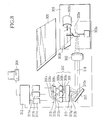
- Fig. 8 shows the structure of a scanning type image display apparatus having a scanning type display optical system that is Embodiment 3 of the present invention.
- This embodiment has the structure of condensing light, emitted from a light source optical system 301, on a screen 305 by a projection optical system 302.
- a scanning optical system 303 having a horizontal scanning mirror 303a and a vertical scanning mirror 303b is provided between the screen 305 and projection optical system 302. Then, it is possible to scan a condensed point of light on the screen 305 by driving the horizontal scanning mirror 303a and vertical scanning mirror 303b respectively driven by actuators 303c and 303d.
- the light source optical system 301 has light sources 306a, 306b, and 306c that emit three color light fluxes respectively.
- the light sources 306a, 306b, and 306c are connected to light source driving circuits 311a, 311b, and 311c respectively.
- the light source driving circuits 311a, 311b, and 311c are connected to a control circuit 312.
- the control circuit 312 is also connected to the actuators 303c and 303d that drive the horizontal scanning mirror 303a and vertical scanning mirror 303b respectively.
- the control circuit 312 outputs modulating signals to the light source driving circuits 311a, 311b, and 311c according to an image signal inputted from an image supplying apparatus 304 such as a personal computer, a television set, a VCR, or a DVD player. Then, the light source driving circuits 311a , 311b, and 311c drive light sources 306a, 306b, and 306c according to the inputted modulating signals so as to modulate the light emitted from the light sources.
- An image display system is constituted by the scanning type image display apparatus and image supplying apparatus.
- the three color light fluxes emitted from the light sources 306a, 306b, and 306c become beams of light by passing through a collimating optical system 307 described later, and are combined into one beam by reflecting on a reflective color combining element 310. This combined beam is condensed by the projection optical system 302 to enter into the horizontal scanning mirror 303a.
- the horizontal scanning mirror 303a is driven by the actuator 303c so as to oscillate in the horizontal direction at high speed, and the beam reflected by the horizontal scanning mirror 303a enters into the vertical scanning mirror 303b.
- the vertical scanning mirror 303b is driven by the actuator 303d so as to oscillate in the vertical direction at high speed. Owing to this, the beam reflected by the vertical scanning mirror 303b is scanned on the screen 305 in the horizontal and vertical directions, and an image is displayed on the screen 305.
- the light source optical system 301 will be described in further detail.
- the three light sources 306a, 306b, and 306c are semiconductor light sources such as laser diodes, or light emitting diodes (inorganic semiconductor light sources or organic semiconductor light sources) that generate light in different wavelength regions such as a red wavelength region (R) of 600 to 670 nm, a green wavelength region (G) of 500 to 570 nm, and a blue wavelength region (B) of 420 to 490 nm, and can directly modulate light emitted therefrom.
- the three light sources may be light emitting devices that use wavelength conversion and are constituted so as to generate light in the above-described wavelength regions.
- These light sources 306a, 306b, and 306c are arranged on a plane approximately orthogonal to a main optical axis 316.
- each of these light fluxes 313r, 313g, and 313b emitted from the light sources 306a, 306b, and 306c have divergence. Nevertheless, each of these light fluxes 313r, 313g, and 313b is made to be approximately parallel light flux (beam of light: 313r', 313g', 313b') by the collimating optical system 307 constituted of the collimating lenses 308a, 308b, and 308c as first optical elements arranged independently on three color optical paths respectively, and a second optical element 309 arranged commonly in the three color optical paths.
- the beams 313r', 313g', and 313b' enter into the approximately same regions on the reflective color combining diffraction optical element 310.
- the respective beams 313r', 313g' and 313b' have incident angles named ⁇ r, ⁇ g, and ⁇ b for the color combining diffraction optical element 310 as shown in Fig. 9.
- a diffraction grating 310a constituted by a plurality of step-wise grating portions with height d which are arranged at pitch P, is formed.
- This diffraction grating 310a is set so that diffraction efficiencies of the zero-th order, minus first order, and plus first order diffracted light in different wavelength regions may become high. That is, the reflective color combining diffraction optical element 310 of this embodiment has the structure that a diffraction order where a diffraction efficiency of an incident light becomes maximum varies according to the wavelength of the incident light.
- diffraction grating 310a characteristics of the diffraction grating 310a are fundamentally similar to those of the diffraction grating 110a of the color combining diffraction optical element 110 according to Embodiment 1 shown in Figs. 10 and 11, height d is set so that the diffraction efficiency of reflection may become high. Furthermore, a reflecting surface is given reflection increase processing so that reflectance may become high.
- the grating pitch P is determined so that beams 313r', 313g' and 313b' entering into the color combining diffraction optical element 310 at incident angles ⁇ r, ⁇ g, and ⁇ b may combine into one beam after being emitted.
- the color composition (combination) is achieved in this manner by the reflective color combining diffraction optical element 310 (diffraction grating 310a), it is not necessary to constitute a color combining system by using a plurality of dichroic mirrors as usual. Hence, it is possible to reduce the number of parts.
- the diffraction grating 310a has a minute shape, the large volume of a dichroic prism is not needed. Therefore, it is possible to achieve the miniaturization of the color combining diffraction optical element 310 itself.
- the reflective color combining diffraction optical element 310 is used in this embodiment, there is an advantage that it is possible to make a color combining diffraction optical element a thinner element so as to achieve an intra-element optical path difference being the same as that in the color combining diffraction optical element according to Embodiment 1. Moreover, since the reflective color composition diffraction optical element 310 uses the reflection of its surface, there is an advantage that utilization efficiency of light is high because of lesser absorption of light by material.
- the light source optical system 301 is divided into the collimating optical system 307 and color combining diffraction optical element 310 in this embodiment, it is possible to achieve the further miniaturization of the light source optical system 301 by integrating the collimating optical system 307, and color combining diffraction optical element 310.
- each of the light fluxes having divergence from the light sources 306a, 306b, and 306c enters into the color combining diffraction optical element 310 after being collimated (being made approximately parallel light flux [beam]), it becomes possible to reduce the variation of an incident angle of a light flux from the same light source to the color combining diffraction optical element 310. Hence, it is possible to reduce the angular dependence of a diffraction efficiency.
- the scanning type image display apparatus (the scanning type display optical system) displaying an image on a screen
- the present invention is not limited to this.
- the scanning type image display optical system As described in Embodiment 1, by reducing the size of a screen, then forming an image by light scan on this screen and then being observed the formed image by observer's eyes through an optical system such as eyepieces, the scanning type image display optical system is constituted so that light may be scanned in an observer's retina. It is possible to apply such structure to a head-mounted display apparatus, an electric view finder optical system, etc.
- the collimating optical system 307 is constituted by the collimating lenses 308a to 308c and the second optical element 309 in this embodiment, the present invention is not limited to this.
- structure can be performed so that each beam may enter into the color combining diffraction optical element 310 in approximately parallel light, it is possible to obtain similar results.
- it is possible to achieve further miniaturization by having such structure that the collimating lens 308a to 308c and the second optical element 309 are integrated to play both actions.
- a diffraction optical element is used as an element that combines a plurality of color light fluxes, it is possible to reduce the number of parts in comparison to the case that a plurality of dichroic mirrors is used. Furthermore, it is possible to achieve the miniaturization of an entire optical system since it is also not necessary to provide a large-scale optical path route. In addition, since a diffraction effect by a single diffraction optical element is used, it is easy to secure desired optical performance in comparison to the case of using a dichroic prism which has a plurality of polarization splitting surfaces, and moreover, it is possible to constitute this at low cost.
Landscapes
- Physics & Mathematics (AREA)
- General Physics & Mathematics (AREA)
- Optics & Photonics (AREA)
- Engineering & Computer Science (AREA)
- Multimedia (AREA)
- Signal Processing (AREA)
- Mechanical Optical Scanning Systems (AREA)
- Lenses (AREA)
- Diffracting Gratings Or Hologram Optical Elements (AREA)
- Transforming Electric Information Into Light Information (AREA)
- Video Image Reproduction Devices For Color Tv Systems (AREA)
Abstract
Description
Claims (7)
- A scanning type display optical system that scans light on a scan surface to display an image, characterized in that the scanning type display optical system comprises:a plurality of light sources emitting light having wavelength regions mutually different;a light combining element combining a plurality of light emitted from the light sources; anda scanning optical system scanning light, combined by the light combining element, on the scan surface, andthat the light combining element is a diffraction optical element.
- The scanning type display optical system according to claim 1, characterized in that a polarized direction of light emitted from at least one of the light sources is approximately parallel in a direction where the diffraction grating is extended in the diffraction optical element, and a polarized direction of light emitted from other light sources is approximately orthogonal to the direction where the diffraction grating is extended in the diffraction optical element.
- The scanning type display optical system according to claim 1, characterized in that the diffraction optical element makes a plurality of light , which enters into the diffraction orders.
- The scanning type display optical system according to one of claims 1 to 3, characterized in that each of the light sources emits light having divergence, and
that a collimating optical system that makes each light flux emitted from the light sources an approximately parallel light flux, is arranged between the light sources and the diffraction optical element - A scanning type image display apparatus, characterized in that the scanning type image display apparatus includes the scanning type display optical system according to one of claims 1 to 4, and
that each of the light sources emits light in a visible light region that is different from others. - The scanning type image display apparatus according to one of claims 1 to 5, characterized in that a grating period in the diffraction optical element is 5 µm or more.
- An image display system, characterized in comprising:the scanning type display apparatus according to one of claims 1 to 6, andan image supplying apparatus supplying an image signal for modulating light emitted from each of the light sources to the scanning type image display apparatus.
Applications Claiming Priority (2)
| Application Number | Priority Date | Filing Date | Title |
|---|---|---|---|
| JP2002104405 | 2002-04-05 | ||
| JP2002104405A JP2003295112A (en) | 2002-04-05 | 2002-04-05 | Scanning image display optical system, scanning image display device, and image display system |
Publications (2)
| Publication Number | Publication Date |
|---|---|
| EP1351522A2 true EP1351522A2 (en) | 2003-10-08 |
| EP1351522A3 EP1351522A3 (en) | 2006-04-19 |
Family
ID=28035967
Family Applications (1)
| Application Number | Title | Priority Date | Filing Date |
|---|---|---|---|
| EP03251708A Withdrawn EP1351522A3 (en) | 2002-04-05 | 2003-03-19 | Scanning type display optical system, scanning image display apparatus, and image display system |
Country Status (3)
| Country | Link |
|---|---|
| US (1) | US6798575B2 (en) |
| EP (1) | EP1351522A3 (en) |
| JP (1) | JP2003295112A (en) |
Cited By (11)
| Publication number | Priority date | Publication date | Assignee | Title |
|---|---|---|---|---|
| KR100703525B1 (en) | 2005-12-19 | 2007-04-03 | 삼성전자주식회사 | Wavelength conversion light source |
| DE102007025330A1 (en) * | 2007-05-31 | 2008-12-11 | Osram Gesellschaft mit beschränkter Haftung | Image projecting method for use in projection device i.e. laser projector, involves determining deviation of projection of beam on projection area and varying intensity of beam over time according to determined deviations |
| EP2061258A2 (en) * | 2007-11-15 | 2009-05-20 | Funai Electric Co., Ltd. | Image display apparatus |
| EP2229604A4 (en) * | 2007-12-03 | 2011-05-11 | Digislide Holdings Ltd | A miniaturised projection device using an led array and dichroic wedge |
| US9039198B2 (en) | 2006-11-14 | 2015-05-26 | Osram Gesellschaft Mit Beschraenkter Haftung | Projection apparatus having improved projection properties, and method and procedure, respectively, for projecting an image |
| DE102013226645A1 (en) | 2013-12-19 | 2015-06-25 | Osram Gmbh | Generating a Lichtabstrahlmusters by illuminating a phosphor surface |
| DE102013226622A1 (en) | 2013-12-19 | 2015-06-25 | Osram Gmbh | Lighting device with fluorescent surface |
| DE102013226650A1 (en) | 2013-12-19 | 2015-06-25 | Osram Gmbh | Generating a Lichtabstrahlmusters by illuminating a phosphor surface |
| WO2015094009A1 (en) * | 2013-12-20 | 2015-06-25 | Huawei Technologies Co., Ltd. | Beam combining device |
| EP2600053A4 (en) * | 2010-07-30 | 2016-06-01 | Sony Corp | LIGHTING AND DISPLAY DEVICES |
| DE102019204552A1 (en) * | 2019-04-01 | 2020-10-01 | Robert Bosch Gmbh | Optical system |
Families Citing this family (29)
| Publication number | Priority date | Publication date | Assignee | Title |
|---|---|---|---|---|
| TW472225B (en) * | 2001-06-08 | 2002-01-11 | Shiu-Hua Huang | Sequential type projection apparatus |
| US7088353B2 (en) * | 2002-07-10 | 2006-08-08 | Fuji Photo Film Co., Ltd. | Display device |
| JP2004275542A (en) * | 2003-03-17 | 2004-10-07 | Olympus Corp | Capsule endoscope |
| US7252394B1 (en) * | 2003-07-03 | 2007-08-07 | Advanced Numicro Systems, Inc. | Laser projection display and illumination device with MEMS scanning mirror for indoor and outdoor applications |
| JP4077484B2 (en) * | 2004-01-29 | 2008-04-16 | 松下電器産業株式会社 | Light source device |
| KR100584403B1 (en) * | 2004-04-01 | 2006-05-26 | 삼성전자주식회사 | Diffraction grating and laser TV using it |
| JP2006047421A (en) * | 2004-07-30 | 2006-02-16 | Canon Inc | Display optical system and image projection apparatus |
| KR100632606B1 (en) * | 2004-08-19 | 2006-10-09 | 삼성전기주식회사 | Optical modulator multi-light scanning device using color-coded slits |
| US9201295B2 (en) * | 2005-01-25 | 2015-12-01 | Jabil Circuit, Inc. | High efficiency LED optical engine for a digital light processing (DLP) projector and method of forming same |
| US20060215138A1 (en) * | 2005-03-22 | 2006-09-28 | Matsushita Electric Industrial Co., Ltd. | Laser beam pattern generator with a two-axis scan mirror |
| JP2006301113A (en) * | 2005-04-18 | 2006-11-02 | Ricoh Co Ltd | Multi-beam light source unit, optical scanning device, image forming device, light beam synthesis element, optical system, optical equipment |
| US7549804B2 (en) * | 2005-06-16 | 2009-06-23 | Avago Technologies Fiber Ip (Singapore) Pte. Ltd. | Optical unit having a transmitter including a semiconductor source and fiber optic element and method of making same |
| KR100890291B1 (en) * | 2005-12-29 | 2009-03-26 | 삼성전기주식회사 | Raster scanning display device using diffractive optical modulator |
| JP5013578B2 (en) * | 2006-02-07 | 2012-08-29 | 株式会社リコー | Multi-beam light source unit, optical scanning device, and image forming apparatus |
| JP5013579B2 (en) * | 2006-02-07 | 2012-08-29 | 株式会社リコー | Multi-beam light source unit, optical scanning device, and image forming apparatus |
| US7959302B2 (en) * | 2006-03-28 | 2011-06-14 | Seiko Epson Corporation | Display device and game machine |
| JP5037851B2 (en) * | 2006-04-28 | 2012-10-03 | 株式会社リコー | Optical scanning apparatus and image forming apparatus |
| US20070273843A1 (en) * | 2006-05-25 | 2007-11-29 | Miklos Stern | Arrangement for, and method of, increasing brightness of a projected image with drive-assisted flyback |
| JP5024859B2 (en) * | 2006-06-14 | 2012-09-12 | 株式会社リコー | Image display device |
| CA2632346A1 (en) * | 2006-10-06 | 2008-04-10 | Lalley Brothers Scientific Llc | Three-dimensional internal back-projection system and method for using the same |
| US8248679B2 (en) * | 2007-08-21 | 2012-08-21 | Prsym, Inc. | Multibeam scanning device |
| US8493289B2 (en) * | 2007-11-05 | 2013-07-23 | Texas Instruments Incorporated | Scanning mirror based display system and method |
| DE102013208819A1 (en) * | 2013-05-14 | 2014-11-20 | Robert Bosch Gmbh | Laser projection apparatus and laser projection method for projecting laser beams onto a projection plane |
| JP6451210B2 (en) * | 2014-10-29 | 2019-01-16 | セイコーエプソン株式会社 | Display device |
| JP6464708B2 (en) * | 2014-12-08 | 2019-02-06 | セイコーエプソン株式会社 | Image display device |
| US10288245B2 (en) * | 2015-06-16 | 2019-05-14 | Mitsubishi Electronic Corporation | Headlight with illumination device having rotatable transmissive element for shifting light concentration position |
| WO2019144063A1 (en) * | 2018-01-20 | 2019-07-25 | Ntt Docomo, Inc. | Light source for projection display |
| CN109309825B (en) * | 2018-11-26 | 2024-01-23 | 长兴博泰电子科技股份有限公司 | Laser animation projection device and control method |
| WO2020110757A1 (en) * | 2018-11-29 | 2020-06-04 | ソニー株式会社 | Video projection device |
Family Cites Families (10)
| Publication number | Priority date | Publication date | Assignee | Title |
|---|---|---|---|---|
| KR940006154B1 (en) | 1988-05-31 | 1994-07-08 | 주식회사 금성사 | Lasor scanning system for color 3-d image display |
| US5027359A (en) * | 1989-10-30 | 1991-06-25 | Massachusetts Institute Of Technology | Miniature Talbot cavity for lateral mode control of laser array |
| DE4324849C2 (en) * | 1993-07-23 | 1995-07-13 | Schneider Rundfunkwerke Ag | Video system for generating a color video image on a screen |
| IL107508A (en) * | 1993-11-05 | 1996-12-05 | Orbotech Ltd | Method and apparatus for recording on optically-sensitive media |
| US5682265A (en) * | 1994-02-18 | 1997-10-28 | Massachusetts Institute Of Technology | Diffractive microstructures for color separation and fusing |
| DE19616843A1 (en) * | 1996-04-26 | 1997-11-06 | Ldt Gmbh & Co | Method and device for transmitting a light beam of low divergence, which is provided for illuminating pixels of a video image and is coupled into an optical fiber |
| EP0823667A2 (en) * | 1996-08-06 | 1998-02-11 | Nikon Corporation | Alignment apparatus and exposure apparatus equipped with same |
| US6252565B1 (en) * | 1998-10-30 | 2001-06-26 | The United States Of America As Represented By The Secretary Of The Army | Elliptical cavity optical retinal display |
| JP4574774B2 (en) | 2000-01-06 | 2010-11-04 | オリンパス株式会社 | Video display device |
| JP4220102B2 (en) * | 2000-05-02 | 2009-02-04 | 富士フイルム株式会社 | Dynamic change detection method, dynamic change detection apparatus, and ultrasonic diagnostic apparatus |
-
2002
- 2002-04-05 JP JP2002104405A patent/JP2003295112A/en not_active Abandoned
-
2003
- 2003-03-19 EP EP03251708A patent/EP1351522A3/en not_active Withdrawn
- 2003-04-01 US US10/404,527 patent/US6798575B2/en not_active Expired - Fee Related
Cited By (17)
| Publication number | Priority date | Publication date | Assignee | Title |
|---|---|---|---|---|
| KR100703525B1 (en) | 2005-12-19 | 2007-04-03 | 삼성전자주식회사 | Wavelength conversion light source |
| US9039198B2 (en) | 2006-11-14 | 2015-05-26 | Osram Gesellschaft Mit Beschraenkter Haftung | Projection apparatus having improved projection properties, and method and procedure, respectively, for projecting an image |
| DE102007025330A1 (en) * | 2007-05-31 | 2008-12-11 | Osram Gesellschaft mit beschränkter Haftung | Image projecting method for use in projection device i.e. laser projector, involves determining deviation of projection of beam on projection area and varying intensity of beam over time according to determined deviations |
| EP2061258A2 (en) * | 2007-11-15 | 2009-05-20 | Funai Electric Co., Ltd. | Image display apparatus |
| EP2229604A4 (en) * | 2007-12-03 | 2011-05-11 | Digislide Holdings Ltd | A miniaturised projection device using an led array and dichroic wedge |
| EP2600053A4 (en) * | 2010-07-30 | 2016-06-01 | Sony Corp | LIGHTING AND DISPLAY DEVICES |
| US9897283B2 (en) | 2013-12-19 | 2018-02-20 | Osram Gmbh | Generating a light emission pattern by illuminating a phosphor surface |
| DE102013226650A1 (en) | 2013-12-19 | 2015-06-25 | Osram Gmbh | Generating a Lichtabstrahlmusters by illuminating a phosphor surface |
| DE102013226622A1 (en) | 2013-12-19 | 2015-06-25 | Osram Gmbh | Lighting device with fluorescent surface |
| DE102013226645A1 (en) | 2013-12-19 | 2015-06-25 | Osram Gmbh | Generating a Lichtabstrahlmusters by illuminating a phosphor surface |
| US9933134B2 (en) | 2013-12-19 | 2018-04-03 | Osram Gmbh | Lighting device with phosphor surface |
| WO2015094009A1 (en) * | 2013-12-20 | 2015-06-25 | Huawei Technologies Co., Ltd. | Beam combining device |
| CN105814475A (en) * | 2013-12-20 | 2016-07-27 | 华为技术有限公司 | Light beam combining equipment |
| US9823481B2 (en) | 2013-12-20 | 2017-11-21 | Huawei Technologies Co., Ltd. | Beam combining device having a diffractive grating surface |
| CN105814475B (en) * | 2013-12-20 | 2019-05-28 | 华为技术有限公司 | beam combining equipment |
| DE102019204552A1 (en) * | 2019-04-01 | 2020-10-01 | Robert Bosch Gmbh | Optical system |
| DE102019204552B4 (en) | 2019-04-01 | 2024-09-19 | Robert Bosch Gmbh | Optical system |
Also Published As
| Publication number | Publication date |
|---|---|
| EP1351522A3 (en) | 2006-04-19 |
| US6798575B2 (en) | 2004-09-28 |
| JP2003295112A (en) | 2003-10-15 |
| US20030189742A1 (en) | 2003-10-09 |
Similar Documents
| Publication | Publication Date | Title |
|---|---|---|
| EP1351522A2 (en) | Scanning type display optical system, scanning image display apparatus, and image display system | |
| JP3060049B2 (en) | Image projection device | |
| US5237435A (en) | Multicolor projector employing diffraction grating type liquid crystal light modulators | |
| US5626408A (en) | Illumination system for a color projection device and circular polarizer suitable for use in such an illumination system, and color image projection device comprising such an illumination system and circular polarizer | |
| EP0993203B1 (en) | Projection-type display device and method of adjustment thereof | |
| US20060098283A1 (en) | Polarization beam splitter and liquid crystal projector apparatus | |
| JPH11271744A (en) | Color liquid crystal display device | |
| JP3417757B2 (en) | Liquid crystal display device and light beam separating method thereof | |
| JP3292118B2 (en) | Projection display device | |
| JP3060230B2 (en) | Image projection device | |
| KR20040054664A (en) | Image display | |
| JP2000314852A (en) | Projection display device | |
| JP3402527B2 (en) | Reflective color image projector | |
| JP2002182307A (en) | Projection type display device | |
| KR100254335B1 (en) | LCD Display | |
| US6454413B1 (en) | Image projection system | |
| US20030048421A1 (en) | Liquid crystal projector | |
| CN115542558B (en) | Holographic polarization optical module, near-to-eye display system and augmented reality wearing equipment | |
| JP2007328080A (en) | Projection display device | |
| JPH075410A (en) | LCD projector | |
| JP2018036546A (en) | Projection display | |
| JP2800812B2 (en) | Color image generation unit | |
| JP2005106901A (en) | Image projection device | |
| JP5266631B2 (en) | Projector and its optical engine | |
| JP3615869B2 (en) | Liquid crystal projector and projection display system using the same |
Legal Events
| Date | Code | Title | Description |
|---|---|---|---|
| PUAI | Public reference made under article 153(3) epc to a published international application that has entered the european phase |
Free format text: ORIGINAL CODE: 0009012 |
|
| AK | Designated contracting states |
Kind code of ref document: A2 Designated state(s): AT BE BG CH CY CZ DE DK EE ES FI FR GB GR HU IE IT LI LU MC NL PT RO SE SI SK TR |
|
| AX | Request for extension of the european patent |
Extension state: AL LT LV MK |
|
| PUAL | Search report despatched |
Free format text: ORIGINAL CODE: 0009013 |
|
| AK | Designated contracting states |
Kind code of ref document: A3 Designated state(s): AT BE BG CH CY CZ DE DK EE ES FI FR GB GR HU IE IT LI LU MC NL PT RO SE SI SK TR |
|
| AX | Request for extension of the european patent |
Extension state: AL LT LV MK |
|
| 17P | Request for examination filed |
Effective date: 20061019 |
|
| AKX | Designation fees paid |
Designated state(s): DE FR GB |
|
| 17Q | First examination report despatched |
Effective date: 20061222 |
|
| STAA | Information on the status of an ep patent application or granted ep patent |
Free format text: STATUS: THE APPLICATION HAS BEEN WITHDRAWN |
|
| 18W | Application withdrawn |
Effective date: 20070423 |