EP1351464A2 - QAM with fractional rates - Google Patents
QAM with fractional rates Download PDFInfo
- Publication number
- EP1351464A2 EP1351464A2 EP03007394A EP03007394A EP1351464A2 EP 1351464 A2 EP1351464 A2 EP 1351464A2 EP 03007394 A EP03007394 A EP 03007394A EP 03007394 A EP03007394 A EP 03007394A EP 1351464 A2 EP1351464 A2 EP 1351464A2
- Authority
- EP
- European Patent Office
- Prior art keywords
- data
- signal
- output
- value
- values
- Prior art date
- Legal status (The legal status is an assumption and is not a legal conclusion. Google has not performed a legal analysis and makes no representation as to the accuracy of the status listed.)
- Withdrawn
Links
Images












Classifications
-
- H—ELECTRICITY
- H04—ELECTRIC COMMUNICATION TECHNIQUE
- H04L—TRANSMISSION OF DIGITAL INFORMATION, e.g. TELEGRAPHIC COMMUNICATION
- H04L27/00—Modulated-carrier systems
- H04L27/32—Carrier systems characterised by combinations of two or more of the types covered by groups H04L27/02, H04L27/10, H04L27/18 or H04L27/26
- H04L27/34—Amplitude- and phase-modulated carrier systems, e.g. quadrature-amplitude modulated carrier systems
Definitions
- This invention relates to a multi-level modulation/demodulation technique and, more particularly, to a multi-level modulation apparatus, a multi-level demodulation apparatus, a multi-level modulation/demodulation communication system, a program and a modulation/demodulation method.
- the present invention provides a multi-level modulation apparatus for multi-level modulation of an input data string to output a communication signal, comprising a data string number conversion circuit(2) for converting the input data string into an input data signal made up by (3p+1) strings of binary signals, where p is an integer not less than 3, a first data conversion circuit(3) supplied with the input data signal output from the data string number conversion circuit(2) for converting the input data signal to output the converted input data signal, a second data conversion circuit (4) supplied with the input data signal output from the data string number conversion circuit and with an output signal of the first data conversion circuit(3) to convert the supplied signal into three sets of output signals, termed first, second and third output signals, each being a (p+1) string output signal, a parallel-to-serial conversion circuit(5), supplied with and time-division multiplexing the three sets of (p+1) string output signals, output by the second data conversion circuit, to output resulting output signals, and an multi-level modulating unit(6) supplied with the output signal
- the present invention provides a computer program product (which may be stored in a medium which is accessible by a computer), which cause a computer composing a multi-level modulation apparatus to perform the processing of multi-level modulation of 3p+1 strings of an input data signal, where p is an integer not less than 3.
- the present invention provides a program causing a computer composing a multi-level modulation apparatus to perform the processing of performing multi-level demodulation of communication signal and outputting a demodulated data signal of (3p+1) strings, where p is an integer not less than 3.
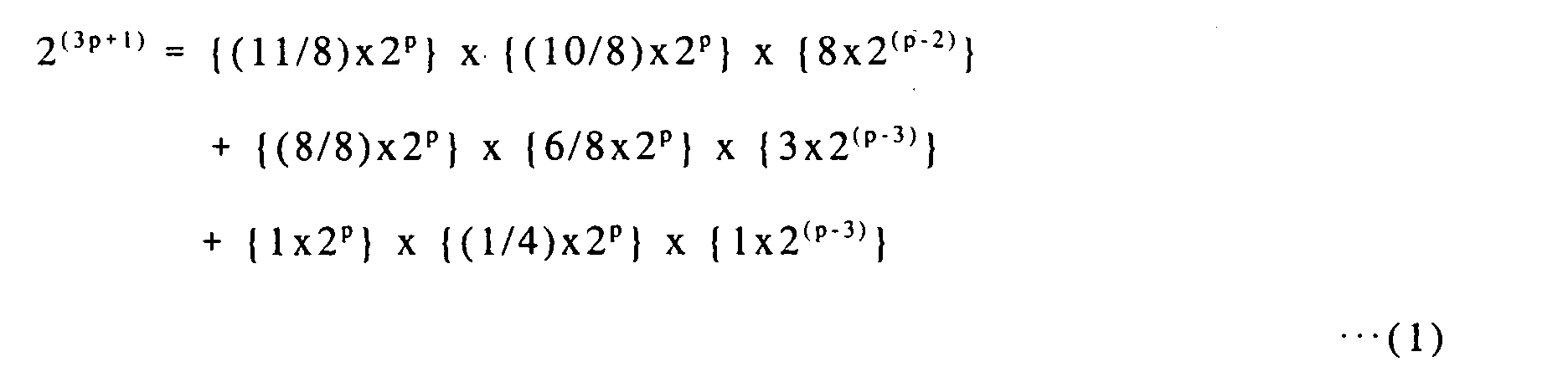
- the program causes the computer to perform the processing in which the communication signals are received as first to third data string signals for demodulation and converted into the (3p+1) data demodulated signals, (11/8)x2 p values are received as the first demodulated data string signals, and in which, if the first demodulated data string signal takes on a value from 1 to 8x2 (p-3) , predetermined (11/8)x2 p and (10/8)x2 p values are received as the second and third demodulated data string signals, respectively, whereas, if the first demodulated signal takes on a value from 1 + 8x2 (p-3) to 8x2 (p-3) +3x2 (p-3) , predetermined (8/8)x2 p and (6/8)x2 p values are received as the second and third demodulated data string signals, respectively, with predetermined demodulated data values being taken on based on the values indicated by the first to third demodulated data string signals; the demodulated data values being output as (3p+1) strings of demodulated data signals.
- the present invention provides an multi-level modulating/demodulating method for allocating (3p+1) strings of an input signal to three modulation symbols, where p is an integer not less than 3, in which the first modulation symbol uses (11/8)x2 p signal points, if the first modulation symbol takes 1 to 8x2 (p-3) signal points, (11/8)x2 p and (10/8)x2 p signal points, predetermined in association with the input signal, are used as the second and third modulation symbols, whereas, if the first modulation symbol takes 1 + 8x2 (p-3) to 8x2 (p-3) + 3x2 (p-3) points, (8/8)x2 p and (6/8)x2 p signal points, predetermined in association with the input signal, are used as the second and third modulation symbols, respectively.
- (3p+1) strings of an input data signal where p is an integer not less than 2 are converted to three (p+1) strings of signals, each of which is allocated to one independent phase plane.
- the three phase planes are time-division multiplexed as a set and subjected to multi-level modulation.
- the resulting multi-level modulated signals are transmitted.
- (p+1/3) bits may be allocated to the single modulation symbol.
- the number of signals is 2 (p+1/3) .
- 2 (p+1/3) becomes an irrational number so that modulation cannot be achieved as actual number of signal points.
- n-ary number in the QAM system may be approximately 2 (n+1/3) .
- the present invention provides a multi-level modulation apparatus for multi-level modulation of an input data string to output a communication signal, comprising a data string number conversion circuit(2) for converting the input data string into an input data signal made up by (3p+2) strings of binary signals, where p is an integer not less than 2, a first data conversion circuit(3) supplied with the input data signal output from the data string number conversion circuit(2) for converting the input data signal to output the converted input data signal, a second data conversion circuit (4) supplied with the input data signal output from the data string number conversion circuit and with an output signal of the first data conversion circuit to convert the input signal into three sets of output signals, termed first, second and third output signals, each being a (p+1) string output signal, a parallel-to-serial conversion circuit(5), supplied with the three sets of (p+1) string output signals, output by the second data conversion circuit, and a multi-level modulating unit(6) supplied with an output signal of the parallel-to-serial conversion circuit to effect multi-level
- the first data conversion circuit(3) outputs signals indicating values from 1 to (7/4)x2 p , responsive to the value of the input data signal. If the output signal of the first data conversion circuit(3) takes on a value from 1 to 4x2 (p-2) , the second data conversion circuit(4) sets, based on the input data signal, the value of the output signal of the first data conversion circuit(3) as the first output signal and outputs signals representing predetermined (7/4)x2 p and (7/4)x2 p values as the second and third signals, respectively, whereas, if the output signal of the first data conversion circuit takes on a value from1 + 4x2 (p-2) to 4x2 (p-2) + 2x2 (p-2) , the second data conversion circuit(4) sets the value of the output signal of the first data conversion circuit(3) as the first output signal and outputs signals representing predetermined (7/4)x2 p and 1x2 p values as the second and third signals, respectively and, if the output signal of the first data conversion circuit(3) takes on a value from1 + 4x2
- the data inverse-conversion circuit(14) receives signals representing predetermined (7/4)x2 p values as second and third demodulated data string signals. If the first demodulated data string signal takes on a value from 1 + 4x2 (p-2) to 4x2 (p-2) + 2x2 (p-2) , the data inverse-conversion circuit(14) receives signals representing predetermined (7/4)x2 p and 1x2 p values, as second and third demodulated data string signals, respectively, whereas, if the first demodulated data string signal takes on a value from 1 + 4x2 (p-2) + + 2x2 (p-2) to 4x2 (p-2) + 2x2 (p-2) + 1x2 (p-2) , the data inverse-conversion circuit(14) receives signals representing predetermined 1x2 p and (1/4)x2 p values, as second and third demodulated data string signals,
- (3p+2) strings of an input data signal where p is an integer not less than 2 are converted to three (p+1) strings of signals, each of which is allocated to one independent phase plane.
- the three phase planes are time-division multiplexed as a set and subjected to multi-level modulation and the resulting multi-level modulated signals are transmitted.
- (p+2/3) bits may be allocated to the single modulation symbol.
- the first data conversion circuit(3) outputs signals indicating values from 1 to 15x2( p-3) , responsive to the value of the input data signal. If the output signal of the first data conversion circuit takes on a value from 1 to 8x2 (p-3) , the second data conversion circuit sets, based on the input data signal, the value of the output signal of the first data conversion circuit as the first output signal and outputs signals representing predetermined 15x2 (p-3) ,15x2 (p-3) and 12x2 (p-3) values as the second, third and fourth signals, respectively.
- the present invention provides a multi-level demodulating apparatus for demodulating a communication signal to output a demodulated data signal of (4p+3) strings, where p is an integer not less than 3, comprising a multi-level demodulating unit(12) for demodulating the communication signal to output a demodulated received data string signal, a serial-to-parallel conversion circuit(13) for receiving and time-division demultiplexing the demodulated received data string signal for modulation to output first, second, third and fourth demodulated data string signals(131-134), and a data inverse-conversion circuit(14) supplied with the first, second, third and fourth demodulated data string signals to output the demodulated data signal of (4p+3) strings(141).
- the data inverse-conversion circuit(14) receives signals representing predetermined 15x2 (p-3) , 15x2 (p-3) and 12x2 (p-3) values as second, third and fourth demodulated data string signals. If the first demodulated data string signal takes on a value from 8x2 (p-3) + 1 to 8x2 (p-3) + 4x2 (p-3) , the data inverse-conversion circuit(14) receives signals representing predetermined 15x2 (p-3) , 12x2 (p-3) and 12x2 (p-3) values, as second, third and fourth demodulated data string signals, respectively.
- the data inverse-conversion circuit(14) receives signals representing predetermined 12x2 (p-3) , 12x2 (p- 3) and 8x2 (p-3) values, as second, third and fourth demodulated data string signals, respectively.
- the data inverse-conversion circuit(14) receives signals representing predetermined 8x2 (p-3) , 7x2 (p-3) and 4x2 (p-3) values, as second, third and fourth demodulated data string signals, respectively.
- the present invention provides a multi-level modulating/demodulating method for allocating (4p+3) strings of an input signal to four modulation symbols, where p is an integer not less than 3, wherein the first modulation symbol uses 15x2 (p-3) signal points. If the first modulation symbol takes 1 to 8x2 (p-3) signal points, 15x2 (p-3) , 15x2 (p-3) and 12x2 (p-3) signal points, predetermined in association with the input signal, are used as the second, third and fourth modulation symbols.
- the first modulation symbol takes 8x2 (p-3) + 4x2 (p-3) + 2x2 (p-3) +1 to 8x2 (p-3) + 4x2 (p-3) + 2x2 (p-3) + 1x2 (p-3) signal points, 8x2 (p-3) , 7x2 (p-3) and 4x2 (p-3) signal points, predetermined in association with the input signal, are used as the second, third and fourth modulation symbols, respectively.
- (4p+3) strings of input data signals where p is an integer not less than 3, are converted into four (p+1) strings of signals, which are then allocated to respective independent phase planes.
- These four planes are tine-division multiplexed as a set, multi-level modulated and output.
- the first modulation symbol takes 1 + 8x2 (p-3) to 8x2 (p-3) + 3x2 (p-3) signal points
- (8/8)x2 p and (6/8)x2 p values predetermined in association with the input signal
- the first modulation symbol takes 1 + 4x2 (p-3) + 2x2 (p-3) to 4x2 (p-3) + 2x2 (p-3) + 1x2 (p-3) signal points
- (8/8)x2 p values and (6/8)x2 p signal points, predetermined in association with the input signal are used as the second and third modulation symbol, respectively.
- the converter means includes means for executing conversion such that, when the input signal belongs to the first group, the first converted data takes on a value from 1 to 8x2 (p-3) , depending on the value of the input signals, the second and third converted data taking on (11/8)x2 p and (10/8)x2 p values, allocated depending on the value of the input signal, respectively, and that, when the input signal belongs to the second group, the first converted data takes on a value from 1 + 8x2 (p-2) to 8x2 (p-2) + 3x2 (p-2) , depending on the value of the input signals, with the second and third converted data taking on (8/8)x2 p and (6/8)x2 p values, allocated depending on the value of the input signal, respectively.
- the total number of the first signals is (7/4) x 2 p .
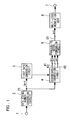
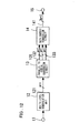
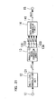
- Fig.1 is a block diagram showing the structure of a multi-level modulation apparatus according to a first embodiment of the present invention.
- a multi-level modulation apparatus of the present embodiment includes an input terminal 1, a conversion circuit 2 for converting the number of data strings, a first data conversion circuit 3, a second data conversion circuit 4, a parallel-to-serial conversion circuit 5, a multi-level modulation unit 6 and an output terminal 7.
- the parallel-to-serial conversion circuit 5 is supplied with the first to third output signals 41 to 43 from the second data conversion circuit 4 and time-division multiplexes these signals to output (p+1) strings of a multiplexed signal 51.
- the serial-to-parallel conversion circuit 13 time-division demultiplexes the received demodulated data string signal 121 to output first to third demodulated data string signals 131 to 133, each being mad up of (p+1) strings.
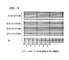
- Fig.3(3) shows the manner in which the signals of Fig.3(2)A, (2)B and (2)C are time-division multiplexed, with the signal of (2)A being output during the period of (3)A, the signal of (2)B being output during the period of (3)B and with the signal of (2)C being output during the period of (3)C.
- step S3 second and third conversion data are generated.
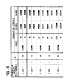
- These conversion data may for example be constituted as shown for example in Fig.4.
- the data inverse-conversion circuit 14 of Fig.8 may be formed as an input/output device of the multi-level demodulation controlling means 16, such that the inverse conversion function of the data inverse-conversion circuit 14 is implemented by a computer forming the multi-level demodulation controlling means 16.
- the control program of the multi-level demodulation controlling means 16 is designed such as to take charge of the function of the data inverse-conversion circuit 14.
- the converter means includes converting means operating such that, when the input signal belongs to the first group, the first converted data takes on a value form 1 to 4x2 (p-2) , depending on the value of the input signals, the second and third converted data taking on (7/4)x2 p and (7/4)x2 p values, allocated depending on the value of the input signal, respectively.
- the first converted data takes on a value from 1 + 4x2 (p-2) to 4x2 (p-2) + 2x2 (p-2) , depending on the value of the input signals, the second and third converted data taking on (7/4)x2 p and 1x2 p values, allocated depending on the value of the input signal, respectively, whereas, when the input signal belongs to the third group, the first converted data takes on a value from 1 + 4x2 (p-2) + 2x2 (p-2) to 4x2 (p-2) + 2x2 (p-2) + 1x2 (p-2) , depending on the value of the input signals, the second and third converted data taking on (1/2)x2 p and (1/4)x2 p values, allocated depending on the value of the input signal, respectively.
- the third term of the right side of the equation (3) indicates that 1 x 2 (p-2) number of times, as to the second and third signals, 1 x 2 p QAM and (1/4) x 2 p QAM are to be executed, respectively.
- the total number of the first signals is (7/4) x 2 p .
- Fig. 11 is a diagram showing the configuration of a multi-level modulation apparatus according to the present embodiment is the same shown in Fig.11.
- a multi-level modulation apparatus of the present embodiment includes an input terminal 1, a conversion circuit 2 for converting the number of data strings, a first data conversion circuit 3, a second data conversion circuit 4, a parallel-to-serial conversion circuit 5, a multi-level modulation unit 6 and an output terminal 7.
- the first data conversion circuit 3 and the second data conversion circuit 4 receive an input data signal 21 which is made up by 3p+2 strings, and which is output from the data string number conversion circuit 2, to output converted signals.
- the first data conversion circuit 3 is responsive to the value of the input data signal 21 to output a signal of (p+1) strings indicating (7/4) x 2 p values.
- the second data conversion circuit 4 receives the output signal from the first data conversion circuit 3 and refers to the value of the input signal 21 to output three set of signals 41, 42, and 43, each being p+1 strings.
- the second data conversion circuit 4 sets this value as a first output signal 41, while outputting signals indicating predetermined (7/4)x2 p kinds of values and signals indicating predetermined 1x2 p values, as second and third output signals 42, 43, respectively.
- the multi-level modulation unit 6 performs multi-level modulation of the multiplexed signals 51 to deliver the modulated signals to the output terminal 7.
- the multi-level demodulating unit 12 demodulates a communication signal, supplied to the input terminal 11, to output a received demodulated data string signal of (p+1) strings 121.
- the serial-to-parallel conversion circuit 13 time-division demultiplexes the received demodulated data string signal 121 to output first to third demodulated data string signals 131 to 133, each being (p+1) strings.
- the data inverse-conversion circuit 14 is supplied with the first to third demodulated data string signals 131 to 133 to output a demodulated data signal of (3P+2) strings 141.
- the data inverse-conversion circuit 14 receives signals indicating predetermined (7/4)x2 p values, as second and third demodulated data string signals.
- the data inverse-conversion circuit 14 receives signals indicating predetermined 1x2 p kinds of values and signals indicating predetermined (1/4)x2 p kinds of values, as the second and third demodulated data string signals, respectively.
- the data inverse-conversion circuit 14 may receive signals indicating predetermined (1/2)x2 p kinds of values and (1/2)x2 p kinds of values, as the second and third demodulated data string signals, respectively.
- a predetermined demodulated data value is generated and output as a demodulated data signal of (3p+2) strings.
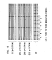
- Fig.13 shows a timing chart illustrating signal conversion in the respective portions in the multi-level modulation apparatus according to the embodiment of the present invention.
- Fig.13(1) shows an input data signal 21 of Fig.11.
- the abscissa of Fig.13 is a time axis, indicating that the input data signal 21 is changed at a preset time interval.
- Fig.13 (2)A, (2)B and (2)C depict first to third output signals 41 to 43 output by the second data conversion circuit 4 of Fig.11.
- Fig.13(3) shows the first to third output signals 41 to 43, output by the second data conversion circuit 4 of Fig.11, respectively.
- Fig.13(3) shows the multiplexed signal 51, output by the parallel-to-serial conversion circuit 5 of Fig.11.
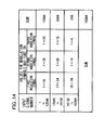
- the second and third modulation symbols may take on values from 1 to 28 and values from 1 to 16, respectively.
- the second and third modulation symbols take on values from 1 to 16 and values from 1 to 4, respectively.
- the second and third modulation symbols may take on values from 1 to 8 and values from 1 to 8, respectively.
- the "eight dots of the first symbol” indicate, beginning from the left end, the coordinate points that can be assumed by the first to third symbols, in the second term of the left side of the above equation (4), by black dots
- the "four dots of the first symbol” indicate, beginning from the left end, the coordinate points that can be assumed by the first to third symbols, in the third term of the left side of the above equation (4) by black dots.
- Fig.17 shows the structure of this further embodiment.
- the same elements as those shown in Fig.11 are denoted by the same reference numerals.
- the multi-level modulation apparatus and the multi-level demodulation apparatus are provided with controlling means, while data conversion tables in the multi-level modulation apparatus and the multi-level demodulation apparatus are formed by RAM (random access memory) devices.
- the data conversion tables stored in the RAM device may be changed by controlling means.
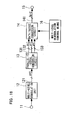
- Fig.18 shows the structure of the multi-level demodulation apparatus of the present modification.
- the same elements as those shown in Fig.12 are depicted by the same reference numerals.
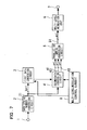
- the multi-level modulation apparatus of the present embodiment is composed of the multi-level modulation apparatus of Fig.12 added by multi-level modulation controlling means 16.
- This multi-level modulation controlling means 16 controls data inverse-conversion circuit 14 to change the inverse data conversion tables, not shown, provided to this conversion circuit 14.
- step S1 the input data signal 21 is input to the multi-level modulation controlling means 8.
- step S2 first conversion data corresponding to the values of the input data signal 21 is generated.
- step S11 first demodulated data is input.
- step S12 second and third modulated data are input.
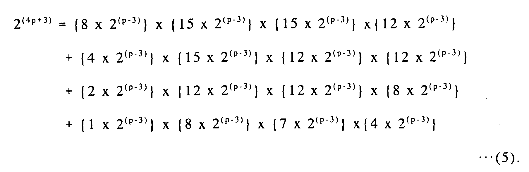
- the fourth term of the right side of the equation (5) indicates that 1 x 2 (p-3) number of times, as to the second, third and fourth signals, 8 x 2 (p-3) QAM, 7 x 2 (p-3) QAM and 4 x 2 (p-3) QAM are to be executed, respectively.
- the first data conversion circuit 3 is responsive to the value of the input data signal 21 of (4p+3) strings to output a signal of four (p+1) strings indicating 15 x 2 (p-3) kinds of values.
- the second data conversion circuit 4 receives the output signal from the first data conversion circuit 3 and refers to the value of the input signal 21 to output four sets of signals 41, 42, 43 and 44, each being (p+1) strings.
- the second data conversion circuit 4 sets this value as a first output signal 41, while outputting signals indicating predetermined 12x2 (p-3) , 12x2 (p-3) and 8x2 (p-3) kinds of values as second, third and fourth output signals 42, 43 and 44.
- the second data conversion circuit 4 sets this value as a first output signal 41, while outputting signals indicating predetermined 4x2 (p-3) , 14x2 (p-3) and 4x2 (p-3) values or predetermined 14x2 (p-3) , 8x2 (p-3) and 2x2 (p-3) kinds of values as second, third and fourth output signals 42, 43 and 44.
- the serial-to-parallel conversion circuit 13 time-division demultiplexes the received demodulated data string signals 121 to output first to fourth demodulated data string signals 131 to 134, each being a (p+1) string.
- the data inverse-conversion circuit 14 receives signals indicating predetermined 8x2 (p-3) , 7x2 (p-3) and 4x2 (p-3) kinds of values and signals, as the second, third and fourth demodulated data string signals, respectively.
- Fig.21(3) shows the multiplexed signal 51, output by the parallel-to-serial conversion circuit 5 of Fig.20.
- Fig.21(3) shows the manner in which the signals of Fig.21(2)A, (2)B, (2)C and (2)D are time-division multiplexed, with the signals of (2)A being output during the period of (3)A, the signal of (2)B being output during the period of (3)B, the signal of (2)C being output during the period of (3)C and with the signal of (2)D being output during the period of (3)D.
- the first one of four modulation symbols takes on a value from 1 to 30.
- the second, third and fourth modulation symbols take on values from 1 to 30, from 1 to 30 and from 1 to 24, respectively.
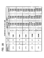
- 16 of 16x30x30x24 of the first term of the left side indicates that the first modulation symbol takes on the values of from 1 to 16
- 30x30x24 indicates that the second, third and fourth modulation symbol take on the values of from 1 to 30, 1 to 30 and from 1 to 24 for each of 1 to 16 of the values of the first modulation symbol, respectively.
- 4 of 4x24x24x16 of the third term of the left side indicates that the first modulation symbol takes on the values of from 25 to 28, while 24x24x16 indicates that the second, third and fourth modulation symbols take on the values of from 1 to 24, 1 to 24 and from 1 to 6 for each of 1 to 16 of the values of the first modulation symbol, respectively.
- 2 of 2x16x14x8 of the fourth term of the left side indicates that the first modulation symbol takes on the values of from 29 to 30, while 16x14x8 indicates that the second, third and fourth modulation symbol take on the values of from 1 to 16, 1 to 14 and from 1 to 8 for each of 29 to 30 of the values of the first modulation symbol, respectively.
- Fig.24 depicts a signal diagram in which the first to third modulation symbols of the modulated signals output by the multi-level modulation unit 6 are represented as a so-called constellation (signal arraying points of the digital modulated wave) on the phase plane.
- constellation signal arraying points of the digital modulated wave
- the coordinate points that can be taken on by the first to fourth symbols, in the first to fourth terms of the left side of the above equation (6) are indicated by black dots. That is, "16 points of the first symbol" of Fig.24 indicate, beginning from the left end, the coordinate points that can be assumed by the first to fourth symbols in the first term of the left side of the above equation (6), by black dots (dots confined within circles).
- the "8 points of the first symbol" indicate, beginning from the left end, the coordinate points that can be assumed by the first to fourth symbols, in the second term of the left side of the above equation (6), by black dots
- the "four points of the first symbol” indicate, beginning from the left end, the coordinate points that can be assumed by the first to fourth symbols, in the third term of the left side of the above equation (6) by black dots
- the "two points of the first symbol” indicate, beginning from the left end, the coordinate points that can be assumed by the first to fourth symbols, in the fourth term of the left side of the above equation (6) by black dots
- the present invention shows a method for construction in a generalized form that can be worked out for an integer p not less than 3.
- the multi-level modulation apparatus of the present embodiment is composed of the multi-level modulation apparatus of Fig.20 added by multi-level modulation controlling means 8.
- This multi-level modulation controlling means 8 controls the first data conversion circuit 3 and the second data conversion circuit 4 to change the data conversion tables, not shown, provided to these circuits.
- Fig.27 shows the structure of the multi-level demodulation apparatus of the present modification.
- the same elements as those shown in Fig.2 are depicted by the same reference numerals.
- the multi-level modulation apparatus of the present embodiment is composed of the multi-level modulation apparatus of Fig.21 added by multi-level modulation controlling means 16.
- This multi-level modulation controlling means 16 controls data inverse-conversion circuit 14 to change the inverse data conversion tables, not shown, provided to this conversion circuit 14.
- the multi-level modulation/demodulation communication system of the present invention may also be provided with the multi-level modulation apparatus shown in Fig.26 and with the multi-level demodulation apparatus shown in Fig.27.
- the first data conversion circuit 3 and the second data conversion circuit 4 of Fig.26 may be constituted as an input/output device for the multi-level modulation controlling means 8, such that data conversion processing by the first data conversion circuit 3 and the second data conversion circuit 4 is carried out by a computer of the multi-level modulation controlling means 8.
- the control program of the multi-level modulation controlling means 8 is designed to perform the processing for substituting the data conversion circuits 3 and 4.
- Fig.28 depicts a flowchart of a program to be executed by a computer of the multi-level modulation controlling means 8 shown in Fig.26.
- the input data signal 21 is input to the multi-level modulation controlling means 8.
- first conversion data corresponding to the values of the input data signal 21 is generated.
- step S3 second, third and fourth conversion data are generated.
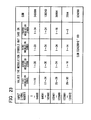
- These conversion data may for example be constituted as shown for example in Fig.23.
- step S4 the first to fourth conversion data are output sequentially to the parallel-to-serial conversion unit 6.
- Fig.28 shows the processing for converting one input data
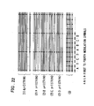
- the input data signals are supplied sequentially, as indicated by the timing chart of Fig.22.
- modulated signals may be sequentially transmitted in a controlled fashion.
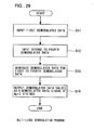
- Fig.29 depicts a flowchart of a program to be executed by the computer of the multi-level demodulation controlling means 16 of Fig.17.
- a step S11 first demodulated data is input.
- second, third and fourth modulated data are input.
- demodulated data values corresponding to the first to fourth demodulated data, are generated. These demodulated data may be formed by preparing an inverse conversion table in accordance with the instance shown in Fig.23.
- demodulated data values are output as (4p+1) strings of demodulated data signals.
- Fig.29 the processing for inputting a set of the demodulated data for back conversion is shown.
Landscapes
- Engineering & Computer Science (AREA)
- Computer Networks & Wireless Communication (AREA)
- Signal Processing (AREA)
- Digital Transmission Methods That Use Modulated Carrier Waves (AREA)
Abstract
Description
That is, there is no suggestion as to means or structure for achieving an QAM system where the level of modulation may be set freely.
The first data conversion circuit(3) outputs signals indicating values from 1 to (11/8)x2p, depending on the value of the input data signal. If the output signal of the first data conversion circuit(3) takes on a value from 1 to 8x2(p-3), the second data conversion circuit(4) sets, based on the input data signal, the value of the output signal of the first data conversion circuit(3) as the first output signal and outputs signals representing predetermined (11/8)x2p and (10/8)x2p values as the second and third signals, respectively, whereas, if the output signal of the first data conversion circuit(3) takes on a value froml + 8x2(p-3) to 8x2(p-3) + 3x2(p-3), the second data conversion circuit(4) sets the value of the output signal of the first data conversion circuit(3) as the first output signal and outputs signals representing predetermined (8/8)x2p and (6/8)x2p values as the second and third signals, respectively.
Still other objects and advantages of the present invention will become readily apparent to those skilled in this art from the following detailed description in conjunction with the accompanying drawings wherein only the preferred embodiments of the invention are shown and described, simply by way of illustration of the best mode contemplated of carrying out this invention. As will be realized, the invention is capable of other and different embodiments, and its several details are capable of modifications in various obvious respects, all without departing from the invention. Accordingly, the drawing and description are to be regarded as illustrative in nature, and not as restrictive.
According to the present invention, as described above, (3p+1) strings of input data are allocated to three modulation symbols, which are then multiplexed in the time domain to a single modulation symbol to transmit (p+1/3) strings of binary data, so that the n-ary number of the QAM system may approximately be 2(p+1/3). Thus, in such a case where there is allowance in the frequency bandwidth with 2nQAM but the required frequency bandwidth is exceeded with 2(n-1)QAM, it is possible to provide a modulation system which represents a compromise between the two QAM systems.

According to the present invention, as described above, (3p+2) strings of input data are allocated to three modulation symbols, which are then multiplexed on the time domain to a single modulation symbol to transmit (p+2/3) strings of binary data, so that the n-ary number of the QAM system may approximately be 2(p+2/3). Thus, in such a case where there is allowance in the frequency bandwidth with 2nQAM but the required frequency bandwidth is exceeded with 2(n-1)QAM, it is possible to provide a modulation system which represents a compromise between the two QAM systems.
According to the present invention, as described above, (4p+3) strings of input data are allocated to three modulation symbols, which are then multiplexed on the time domain to a single modulation symbol to transmit (p+0.75) strings of binary data, so that the n-ary number of the QAM system may approximately be 2(p+0.75). Thus, in such a case where there is allowance in the frequency bandwidth with 2nQAM but the required frequency bandwidth is exceeded with 2(n-1)QAM, it is possible to provide a modulation system which represents a compromise between the two QAM systems.
It should be noted that other objects, features and aspects of the present invention will become apparent in the entire disclosure and that modifications may be done without departing the gist and scope of the present invention as disclosed herein and claimed as appended herewith.
Also it should be noted that any combination of the disclosed and/or claimed elements, matters and/or items may fall under the modifications aforementioned.
Claims (53)
- A apparatus for performing multi-level modulation of an input data string to output a communication signal, said apparatus comprising:a data string number conversion circuit(2) for converting said input data string into an input data signal composed by (3p+1) strings of binary signals, where p is an integer not less than 3, and for outputting said input data signal;a first data conversion circuit(3), receiving said input data signal output from said data string number conversion circuit, for converting said input data signal to output the converted input data signal;a second data conversion circuit(4), receiving said input data signal output from said data string number conversion circuit and an output signal of said first data conversion circuit, for converting the received signal into three sets of output signals, termed first, second and third output signals, each being a (p+1) string output signal;a parallel-to-serial conversion circuit(5), receiving and time-division multiplexing said three sets of (p+1) string output signals output from said second data conversion circuit, to output resulting output signals; anda multi-level modulating unit(6), receiving said output signals of said parallel-to-serial conversion circuit, for effecting multi-level modulation to output the communication signal; whereinsaid first data conversion circuit(3) outputs the output signal indicating a value from 1 to (11/8)x2p, depending on the value of said input data signal;if the output signal of said first data conversion circuit(3) takes on a value from 1 to 8x2(p-3), said second data conversion circuit(4) sets, based on said input data signal, the value of the output signal of said first data conversion circuit(3) as said first output signal and outputs signals representing predetermined (11/8)x2p and (10/8)x2p values as said second and third signals, respectively; andif the output signal of said first data conversion circuit(3) takes on a value from1 + 8x2(p-3) to 8x2(p-3) + 3x2(p-3), said second data conversion circuit(4) sets the value of the output signal of said first data conversion circuit(3) as said first output signal and outputs signals representing predetermined (8/8)x2p and (6/8)x2p values as said second and third signals, respectively.
- A apparatus for demodulating a communication signal to output a demodulated data signal of 3p+1 strings, where p is an integer not less than 3, said apparatus comprising:a multi-level demodulating unit(12) for demodulating said communication signal to output a demodulated received data string signal;a serial-to-parallel conversion circuit(13), receiving and time-division demultiplexing said received demodulated data string signal to output first, second and third demodulated data string signals; anda data inverse-conversion circuit(14), receiving said first, second and third demodulated data string signals to output said demodulated data signal of (3p+1) strings; whereinif said first demodulated data string signal takes on a value from 1 to 8x2(p-2), said data inverse-conversion circuit(14) receives signals representing predetermined (11/8)x2p and (10/8)x2p values, as second and third demodulated data string signals, respectively;if said first demodulated data string signal takes on a value from 1 + 8x2(p-3) to 8x2(p-3) + 3x2(p-3), said data inverse-conversion circuit(14) receives signals representing predetermined (8/8)x2p and (6/8)x2p values, as second and third demodulated data string signals, respectively; andsaid data inverse-conversion circuit(14) outputs the demodulated data taking on a predetermined value, based on the values indicated by said first, second and third demodulated data string signals, as said (3p+1) strings of said demodulated data.
- A multi-level modulation/demodulating communication system comprising:a multi-level modulating apparatus for performing multi-level modulation to output a communication signal, said multi-level modulating apparatus being the apparatus as defined in claim 1; anda multi-level demodulating apparatus for performing multi-level demodulation of a received communication signal sent by the multi-level modulating apparatus, said multi-level demodulating apparatus being the apparatus as defined in claim 2.
- The apparatus as defined in claim 1, further comprising multi-level modulation controlling means(8) for controlling said first and second data conversion circuits for changing the correspondence between said input data signal supplied to said first and second data conversion circuits and output values of output signals from said first and second data conversion circuits.
- The apparatus as defined in claim 2, further comprising multi-level modulation controlling means(16) for controlling said data inverse-conversion circuit for changing the correspondence between said first to third demodulated data string signals supplied to said data inverse-conversion circuit and an output value of an output signal from said data inverse-conversion circuit.
- A multi-level modulation/demodulating communication system comprising:a multi-level modulating apparatus for performing multi-level modulation to output a communication signal, said multi-level modulating apparatus being the apparatus as defined in claim 5; anda multi-level demodulating apparatus for performing multi-level demodulation of a received communication signal sent by the multi-level modulating apparatus, said multi-level demodulating apparatus being the apparatus as defined in claim 6.
- A computer program product causing a computer composing a multi-level modulation apparatus to execute the processing of multi-level modulation of (3p+1) strings of an input data signal, where p is an integer not less than 3; said program causing said computer to execute the processing of converting said input data signal into first, second and third conversion data, in such a manner that
said first conversion data takes on a value from 1 to (11/8)x2p depending on the value of said input data signal;
if said first conversion data takes on a value from 1 to 8x2(p-3), said second and third conversion data take on predetermined (11/8)x2p and (10/8)x2p values, depending on the value of said input data signal, respectively; and
if said first conversion data takes on a value from 1 + 8x2(p-3) to 8x2(p-3) + 3x2(p-3) values, said second and third conversion data take on predetermined (8/8)x2p and (6/8)x2p values, respectively, depending on the value of said input data signal;
said program causing said computer to execute the processing of sequentially outputting said first to third conversion data to a multi-level demodulating unit. - A computer program product causing a computer composing a multi-level demodulation apparatus to perform the processing of multi-level demodulation of a communication signal and outputting a demodulated data signal of (3p+1) strings, where p is an integer not less than 3, said program causing said computer to execute a conversion process which receives said communication signal as demodulated first to third data string signals and converts the received signals into a demodulated signal of (3p+1) strings;
said conversion process receiving (11/8)x2p values as said first demodulated data string signal;
if said first demodulated signal takes on a value from 1 to 8x2(p-3), said conversion process receiving predetermined (11/8)x2p and (10/8)x2p values as said second and third demodulated data string signals, respectively; y;
if said first demodulated signal takes on a value from 1 + 8x2(p-3) to 8x2(p-3) +3x2(p-3), said conversion process receiving predetermined (8/8)x2p and (6/8)x2p values as said second and third demodulated data string signals, respectively; and
said conversion process outputting a demodulated data signal of (3p+1) strings, said demodulated data signal taking on a predetermined value, based on the values indicated by said first to third demodulated data string signals. - A method of performing multi-level modulating/demodulation in which (3p+1) strings of an input signal are allocated to three modulation symbols, where p is an integer not less than 3, said method comprising the steps of:allocating (11/8)x2p signal points as a first modulation symbol;in case of said first modulation symbol taking 1 to 8x2(p-3) signal points, using (11/8)x2p and (10/8)x2p signal points, predetermined in association with said input signal as second and third modulation symbols; andin case of said first modulation symbol taking 1 + 8x2(p-3) to 8x2(p-3) + 3x2(p-3) points, using (8/8)x2p and (6/8)x2p signal points, predetermined in association with said input signal, respectively, as said second and third modulation symbols.
- A modulation apparatus comprising:converting means, receiving an input signal that takes on a value from 1 to a (3p+1)st power of 2, where p is an integer not less than 3, to generate and output first to third converted data based on said input signal; andmeans, receiving said first to third converted data output from said converting means, to effect multi-level modulation thereon to output the resulting data;said converting means classifying said input signal, depending on the values thereof, into two predetermined groups not having common elements, said converter means having means for executing conversion such thatif said input signal belongs to said first group, said first converted data takes on a value form 1 to 8x2(p-3), depending on the value of said input signal, said second and third converted data taking on predetermined (11/8)x2p and (10/8)x2p values, allocated depending on the value of said input signal, respectively; andif said input signal belongs to said second group, said first converted data takes on a value from 1 + 8x2(p-3) to 8x2(p-3) + 3x2(p-3), depending on the value of said input signals, said second and third converted data taking on (8/8)x2p and (6/8)x2p values, allocated depending on the value of said input signal, respectively.
- A method of performing modulation, comprising the steps of:converting a data signal of (3p+1) strings, where p is an integer not less than 3, to three signals, each being a (p+1) string and having a predetermined relation to one another,allocating the three signal of (p+1) string separately to three phase planes, andperforming multi-level modulation, with the three phase planes as a set, by controlling respective numbers of signal points in the three phase planes; wherein a multi-level quadrature amplitude modulation (QAM) is carried out, in which equivalently (p+1/3) bits are allocated to each modulation symbol and the multi-level number is approximated to 2(p+1/3).
- An apparatus for performing multi-level modulation of an input data string to output a communication signal, said apparatus comprising:a data string number conversion circuit(2) for converting said input data string into an input data signal made up by 3p+2 strings of binary signals, where p is an integer not less than 2,and for outputting said input data signal;a first data conversion circuit(3), receiving said input data signal output from said data string number conversion circuit, for converting said input data signal to output the converted input data signal;a second data conversion circuit(4), receiving said input data signal output from said data string number conversion circuit and an output signal of said first data conversion circuit, for converting the received signals into three sets of output signals, termed first, second and third output signals, each being a (p+1) string output signal;a parallel-to-serial conversion circuit(5), receiving said three sets of (p+1) string output signals output by said second data conversion circuit, for performing time-division multiplexing of said three sets of (p+1) string output signals to output resulting output signals; anda multi-level modulating unit(6), receiving said output signal of said parallel-to-serial conversion circuit, for effecting multi-level modulation to output the communication signal; whereinsaid first data conversion circuit(3) outputs the output signal indicating values from 1 to (7/4)x2p, responsive to the value of said input data signal;if the output signal of said first data conversion circuit(3) takes on a value from 1 to 4x2(p-2), said second data conversion circuit(4) sets, based on said input data signal, the value of the output signal of said first data conversion circuit(3) as said first output signal and outputs signals representing predetermined (7/4)x2p and (7/4)x2p values as said second and third signals, respectively;if the output signal of said first data conversion circuit(3) takes on a value from1 + 4x2(p-2) to 4x2(p-2) + 2x2(p-2), said second data conversion circuit(4) sets the value of the output signal of said first data conversion circuit(3) as said first output signal and outputs signals representing predetermined (7/4)x2p and 1x2p values as said second and third signals, respectively; andif the output signal of said first data conversion circuit(3) takes on a value from1 + 4x2(p-2) + 2x2(p-2) to 4x2(p-2) + 2x2(p-2) + 1x2(p-2), said second data conversion circuit(4) sets the value of the output signal of said first data conversion circuit(3) as said first output signal and outputs signals representing predetermined 1x2p and (1/4)x2p values as said second and third signals, respectively.
- An apparatus for performing multi-level modulation of an input data string to output a communication signal, said apparatus comprising:a data string number conversion circuit(2) for converting said input data string into an input data signal made up by 3p+2 strings of binary signals, where p is an integer not less than 2;a first data conversion circuit(3), receiving said input data signal output from said data string number conversion circuit, for converting said input data signal to output the converted input data signal;a second data conversion circuit(4), receiving said input data signal output from said data string number conversion circuit and an output signal of said first data conversion circuit, for converting the received signal into three sets of output signals, termed first, second and third output signals, each being a (p+1) string output signal;a parallel-to-serial conversion circuit(5), receiving said three sets of (p+1) string output signals, output by said second data conversion circuit, for performing time-division multiplexing of said three sets of (p+1) string output signals to output the resulting output signals; anda multi-level modulating unit(6), receiving said output signal of said parallel-to-serial conversion circuit to effect multi-level modulation to output the communication signal; whereinsaid first data conversion circuit(3) outputs signals indicating values from 1 to (7/4)x2p, responsive to the value of said input data signal;if the output signal of said first data conversion circuit(3) takes on a value from 1 to 4x2(p-2), said second data conversion circuit(4) sets, based on said input data signal, the value of the output signal of said first data conversion circuit(3) as said first output signal, and outputs signals representing predetermined (7/4)x2p and (7/4)x2p values as said second and third signals, respectively;if the output signal of said first data conversion circuit(3) takes on a value from1 + 4x2(p-2) to 4x2(p-2) + 2x2(p-2), said second data conversion circuit(4) sets the value of the output signal of said first data conversion circuit(3) as said first output signal, and outputs signals representing predetermined (7/4)x2p and 1x2p values as said second and third signals, respectively; andif the output signal of said first data conversion circuit(3) takes on a value from1 + 4x2(p-2) + 2x2(p-2) to 4x2(p-2) + 2x2(p-2) + 1x2(p-2), said second data conversion circuit sets the value of the output signal of said first data conversion circuit(3) as said first output signal and outputs signals representing predetermined 1x2p and (1/2)x2p values as said second and third signals, respectively.
- An apparatus for demodulating a communication signal to output a demodulated data signal of (3p+2) strings, where p is an integer not less than 2, said apparatus comprising:a multi-level demodulating unit(12) for demodulating said communication signal to output a received demodulated data string signal;a parallel-to-serial conversion circuit(13), receiving and time-division demultiplexing said received demodulated data string signal to output first, second and third demodulated data string signals; anda data inverse-conversion circuit(14), receiving said first, second and third demodulated data string signals and outputting said demodulated data signal of (3p+2) strings; whereinif said first demodulated data string signal takes on a value from 1 to 4x2(p-2), said data inverse-conversion circuit(14) receives signals representing predetermined (7/4)x2p values as second and third demodulated data string signals;if said first demodulated data string signal takes on a value from 1 + 4x2(p-2) to 4x2(p-2) + 2x2(p-2), said data inverse-conversion circuit(14) receives signals representing predetermined (7/4)x2p and 1x2p values, as second and third demodulated data string signals, respectively;if said first demodulated data string signal takes on a value from 1 + 4x2(p-2) + 2x2(p-2) to 4x2(p-2) + 2x2(p-2) + 1x2(p-2), said data inverse-conversion circuit(14) receives signals representing predetermined 1x2p and (1/4)x2p values, as second and third demodulated data string signals, respectively, andsaid data inverse-conversion circuit(14) outputs the demodulated data signal of (3p+2) strings, said demodulated data signal taking on a predetermined value, based on the values indicated by said first, second and third demodulated data string signals.
- An apparatus for demodulating a communication signal to output a demodulated data signal of (3p+2) strings, where p is an integer not less than 2, said apparatus comprising:a multi-level demodulating unit(12) for demodulating said communication signal to output a demodulated received data string signal;a serial-to-parallel conversion circuit(13), receiving and time-division demultiplexing said received demodulated data string signal to output first, second and third demodulated data string signals; anda data inverse-conversion circuit(14), receiving said first, second and third demodulated data string signals and outputting said demodulated data signal of (3p+2) strings; whereinif said first demodulated data string signal takes on a value from 1 to 4x2(p-2), said data inverse-conversion circuit(14) receives signals representing predetermined (7/4)x2p values as second and third demodulated data string signals;if said first demodulated data string signal takes on a value from 1 + 4x2(p-2) to 4x2(p-2) + 2x2(p-2), said data inverse-conversion circuit(14) receives signals representing predetermined (7/4)x2p and 1x2p values, as second and third demodulated data string signals, respectively;if said first demodulated data string signal takes on a value from 1 + 4x2(p-2) + 2x2(p-2) to 4x2(p-2) + 2x2(p-2) + 1x2(p-2), said data inverse-conversion circuit(14) receives signals representing predetermined (1/2)x2p and (1/2)x2p values, as second and third demodulated data string signals, respectively, andsaid data inverse-conversion circuit(14) outputs the demodulated data signal of (3p+2) strings, said demodulated data signal taking on a predetermined value, based on the values indicated by said first, second and third demodulated data string signals.
- A multi-level modulation/demodulating communication system comprising:a multi-level modulating apparatus for performing multi-level modulation to output a communication signal, said multi-level modulating apparatus being the apparatus as defined in claim 12; anda multi-level demodulating apparatus for performing multi-level demodulation of a received communication signal sent by the multi-level modulating apparatus, said multi-level demodulating apparatus being the apparatus as defined in claim 14.
- A multi-level modulation/demodulating communication system comprising:a multi-level modulating apparatus for performing multi-level modulation to output a communication signal, said multi-level modulating apparatus being the apparatus as defined in claim 13; anda multi-level demodulating apparatus for performing multi-level demodulation of a received communication signal sent by the multi-level modulating apparatus, said multi-level demodulating apparatus being the apparatus as defined in claim 15.
- The apparatus as defined in claim 12 or 13 , further comprising
multi-level modulation controlling means(8) for controlling said first and second data conversion circuits for changing the correspondence between said input data signal supplied to said first and second data conversion circuits and output values of output signals from said first and second data conversion circuits. - The apparatus as defined in claim 14 or 15, further comprising
multi-level modulation controlling means(16) for controlling said data inverse-conversion circuit for changing the correspondence between said first to third demodulated data string signals supplied to said data inverse-conversion circuit and an output value of said data inverse-conversion circuit. - A multi-level modulation/demodulating communication system comprising:a multi-level modulating apparatus for performing multi-level modulation to output a communication signal, said multi-level modulating apparatus being the apparatus as defined in claim 18; anda multi-level demodulating apparatus for performing multi-level demodulation of a received communication signal sent by the multi-level modulating apparatus, said multi-level demodulating apparatus being the apparatus as defined in claim 19.
- A computer program product causing a computer composing a multi-level modulation apparatus to perform the processing of multi-level modulation of (3p+2) strings of an input data signal, where p is an integer not less than 2; said program causing said computer to execute the processing of converting said input data signal into first, second and third conversion data in such a manner that
said first conversion data takes on a value from 1 to (7/4)x2p depending on the value of said input data signal;
if said first conversion data takes on a value from 1 to 4x2(p-2), said second and third conversion data takes on predetermined (7/4)x2p values, depending on the value of said input data signal;
if said first conversion data takes on a value from 1 + 4x2(p-2) to 4x2(p-2) + 2x2(p-2) values, said second and third conversion data takes on predetermined (7/4)x2p and 1x2p values, respectively, depending on the value of said input data signal; and
if said first conversion data takes on a value from 1 + 4x2(p-2) + 2x2(p-2) to 4x2(p-2) + 2x2(p-2) + 1x2(p-2) values, said second and third conversion data takes on predetermined 1x2p and (1/4)x2p values, respectively, depending on the value of said input data signal;
said program causing said computer to execute the processing of sequentially outputting said first to third conversion data to a multi-level demodulating unit. - A computer program product causing a computer composing a multi-level demodulation apparatus to perform the processing of multi-level demodulation of a communication signal and outputting a demodulated data signal of (3p+2) strings, where p is an integer not less than 2, said program causing said computer to execute a conversion process which receives said communication signal as demodulated first to third data string signals and converts the received signals into a data demodulated signal of (3p+2) strings;
said conversion process receiving (7/4)x2p values as said first demodulated data string signals;
if said first demodulated signal takes on a value from 1 to 4x2(p-2), said conversion process receiving predetermined (7/4)x2p values as said second and third demodulated data string signals, respectively;
if said first demodulated signal takes on a value from 1 + 4x2(p-2) to 4x2(p-2) +2x2(p-2), said conversion process receiving predetermined (7/4)x2p and 1x2p values as said second and third demodulated data string signals, respectively;
if said first demodulated signal takes on a value from 1 + 4x2(p-2) + 2x2(p-2) to 4x2(p-2) +2x2(p-2) + 1x2(p-2), said conversion process receiving predetermined 1x2p and (1/4)2p values as said second and third demodulated data string signals, respectively; and
said conversion process outputting a demodulated data signal of (3p+2) strings, said demodulated data signal taking on a predetermined value, based on the values indicated by said first to third demodulated data string signals. - A method of performing multi-level modulating/demodulation in which (3p+2) strings of an input signal are allocated to three modulation symbols, where p is an integer not less than 2, comprising the steps of :allocating (7/4)x2p signal points as a first modulation symbol;if said first modulation symbol takes 1 to 4x2(p-3) signal points, using (7/4)x2p signal points, predetermined in association with said input signal as second and third modulation symbols;if said first modulation symbol takes 1 + 4x2(p-2) to 4x2(p-2) + 2x2(p-2) points, using (7/4)x2p and 1x2p signal points, predetermined in association with said input signal, as said second and third modulation symbols, respectively; andif said first modulation symbol takes 1 + 4x2(p-2) + 2x2(p-2) to 4x2(p-2) + 2x2(p-2) + 1x2(p-2) signal points, using 1x2p and (1/4)2p signal points, predetermined in association with said input signal, as said second and thirds symbols, respectively.
- A method of performing multi-level modulating/demodulation in which (3p+2) strings of an input signal are allocated to three modulation symbols, where p is an integer not less than 2, comprising the steps of :allocating (7/4)x2p signal points as a first modulation symbol;if said first modulation symbol takes 1 to 4x2(p-3) signal points, using (7/4)x2p signal points, predetermined in association with said input signal, as second and third modulation symbol;if said first modulation symbol takes 1 + 4x2(p-2) to 4x2(p-2) + 2x2(p-2) signal points, using (7/4)x2p values and 1x2p signal points, predetermined in association with said input signal, as said second and third modulation symbols, respectively; andif said first modulation symbol takes 1 + 4x2(p-2) + 2x2(p-2) to 4x2(p-2) + 2x2(p-2) + 1x2(p-2) signal points, using (1/2)x2p values and (1/2)x2p signal points, predetermined in association with said input signal, as said second and third modulation symbols, respectively.
- A modulation apparatus comprising:converting means receiving an input signal that takes on a value from 1 to a (3p+2) power of 2, where p is an integer not less than 2, to generate and output first to third converted data based on said input signal; andmeans, receiving said first to third converted data to effect multi-level modulation thereon to output the resulting data;said converting means classifying said input signal, depending on the values thereof, into three predetermined groups not having common elements,said converter means including converting means operating such thatif said input signal belongs to said first group, said first converted data takes on a value form 1 to 4x2(p-2), depending on the value of said input signal, said second and third converted data taking on (7/4)x2p and (7/4)x2p values, allocated depending on the value of said input signal, respectively;if said input signal belongs to said second group, said first converted data takes on a value from 1 + 4x2(p-2) to 4x2(p-2) + 2x2(p-2), depending on the value of said input signal, said second and third converted data taking on (7/4)x2p and 1x2p values, allocated depending on the value of said input signal, respectively; andif said input signal belongs to said third group, said first converted data takes on a value from 1 + 4x2(p-2) + 2x2(p-2) to 4x2(p-2) + 2x2(p-2) + 1x2(p-2), depending on the value of said input signals, said second and third converted data taking on 1x2p and (1/4)x2p values, allocated depending on the value of said input signal, respectively.
- A modulation apparatus comprising:converting means receiving an input signal that takes on a value from 1 to a (3p+2) power of 2, where p is an integer not less than 2, to generate and output first to third converted data based on said input signal; andmeans receiving said first to third converted data to effect multi-level modulation thereon to output the resulting data;said converting means classifying said input signal, depending on the values thereof, into three predetermined groups not having common elements,said converter means including means operating such thatif said input signal belongs to said first group, said first converted data takes on a value form 1 to 4x2(p-2), depending on the value of said input signal, said second and third converted data taking on (7/4)x2p and (7/4)x2p values, allocated depending on the value of said input signal, respectively;if said input signal belongs to said second group, said first converted data takes on a value from 1 + 4x2(p-2) to 4x2(p-2) + 2x2(p-2), depending on the value of said input signal, said second and third converted data taking on (7/4)x2p and 1x2p values, allocated depending on the value of said input signal, respectively; andif said input signal belongs to said third group, said first converted data takes on a value from 1 + 4x2(p-2) + 2x2(p-2) to 4x2(p-2) + 2x2(p-2) + 1x2(p-2), depending on the value of said input signal, said second and third converted data taking on (1/2)x2p and (1/2)x2p values, allocated depending on the value of said input signal, respectively.
- A method of performing multi-level modulating, said method comprising the steps of:converting a data signal of (3p+2) strings, where p is an integer not less than 2, to three signals, each being a (p+1) strings signal and having a predetermined relation to one another;allocating the three signals of (p+1) strings separately to three phase planes; andperforming multi-level modulation with the three phase planes as a set, by controlling the numbers of the signal points in the three phase planes; wherein a multi-level quadrature amplitude modulation (QAM) is carried out, in which equivalently (p+2/3) bits are allocated to each modulation symbol and the multi-level number is approximated to 2(p+2/3).
- An apparatus for performing multi-level modulation of an input data string to output a communication signal, said apparatus comprising:a data string number conversion circuit(2) for converting the input data string into an input data signal made up by 4p+3 strings of binary signals, where p is an integer not less than 3, and for outputting said input data signal;a first data conversion circuit(3), receiving the input data signal output from the data string number conversion circuit for converting the input data signal to output the converted input data signal;a second data conversion circuit(4), receiving the input data signal output from the data string number conversion circuit and an output signal of the first data conversion circuit to convert the received signal into four sets of output signals, termed first, second, third and fourth output signals, each being a (p+3) string output signal;a parallel-to-serial conversion circuit(5), receiving and time-division multiplexing the four sets of (p+1) string output signals, output by the second data conversion circuit, to output resulting output signals; anda multi-level modulating unit(6), receiving the output signal of the parallel-to-serial conversion circuit, for effecting multi-level modulation to output the communication signal; whereinthe first data conversion circuit(3) outputs the output signal indicating values from 1 to 15x2(p-3), responsive to the value of the input data signal;if the output signal of the first data conversion circuit takes on a value from 1 to 8x2(p-3), the second data conversion circuit(4) sets, based on the input data signal, the value of the output signal of the first data conversion circuit as the first output signal and outputs signals representing predetermined 15x2(p-3),15x2(p-3) and 12x2(p-3) values as the second, third and fourth signals, respectively;if the output signal of the first data conversion circuit takes on a value from 8x2(p-3) + 1 to 8x2(p-3) + 4x2(p-3),the second data conversion circuit(4) sets the value of the output signal of the first data conversion circuit as the first output signal and outputs signals representing predetermined 15x2(p-3), 12x2(p-3) and 12x2(p-3) values as the second, third and fourth output signals, respectively;if the output signal of the first data conversion circuit takes on a value from 8x2(p-3) + 4x2(p-3) + 1 to 8x2(p-3) + 4x2(p-3) + 2x2(p-3), the second data conversion circuit(4) sets the value of the output signal of the first data conversion circuit as the first output signal and outputs signals representing predetermined 12x2(p-3), 12x2(p-3) and 8x2(p-3) values as the second, third and fourth signals, respectively, andif the output signal of the first data conversion circuit takes on a value from 8x2(p-3) + 4x2(p-3) + 2x2(p-3) + 1 to 8x2(p-3) + 4x2(p-3) + 2x2(p-3) + 1x2(p-3, said second data conversion circuit(4) sets the value of the output signal of said first data conversion circuit as said first output signal and outputs signals representing predetermined 8x2(p-3), 7x2(p-3) and 4x2(p-3) values as said second, third and fourth signals, respectively.
- The apparatus as defined in claim 28, wherein, when values from 1 to 15x2(p-3), are classified by the first data conversion circuit as said output signal of said first data conversion circuit, responsive to the value of said input data signal, the output signal of said first data conversion circuit, taking 8x2(p-3), 4x2(p-3), 2x2(p-3) and 1x2(p-3) values, is output as the sequence thereof is interchanged.
- The apparatus as defined in claim 28 or 29, wherein, if the output signal of said first data conversion circuit takes on a value from 8x2(p-3) + 4x2(p-3) + 2x2(p-3) + 1 to 8x2(p-3) + 4x2(p-3) + 2x2(p-3) + 1x2(p-3), said second data conversion circuit sets the value of the output signal of said first data conversion circuit as said first output signal to output predetermined values of 4x2(p-3), 14x2(p-3) and 4x2(p-3) values or predetermined values of 14x2(p-3), 8x2(p-3) and 2x2(p-3) values, as said second, third and fourth output signals, respectively.
- The apparatus as defined in any one of claims 28 to 30, wherein said second data conversion circuit outputs second to fourth output signals as the sequence of predetermined plural values thereof is interchanged.
- An apparatus for performing multi-level demodulation of a communication signal to output a demodulated data signal of (4p+3) strings, where p is an integer not less than 3, said apparatus comprising:a multi-level demodulating unit(12) for demodulating said communication signals to output a received demodulated data string signal;a serial-to-parallel conversion circuit(13), receiving and time-division demultiplexing said received demodulated data string signal to output first, second, third and fourth demodulated data string signals; anda data inverse-conversion circuit(14), receiving said first, second, third and fourth demodulated data string signals to output said demodulated data signal of 4p+3 strings; whereinif said first demodulated data string signal takes on a value from 1 to 8x2(p-3), said data inverse-conversion circuit(14) receives signals representing predetermined 15x2(p-3),15x2(p-3) and 12x2(p-3) values as second, third and fourth demodulated data string signals, respectively;if said first demodulated data string signal takes on a value from 8x2(p-3) +1 to 8x2(p-3) + 4x2(p-3), said data inverse-conversion circuit(14) receives signals representing predetermined 15x2(p-3), 12x2(p-3) and 12x2(p-3) values, as second, third and fourth demodulated data string signals, respectively;if said first demodulated data string signal takes on a value from 8x2(p-3) + 4x2(p-3) + 1 to 8x2(p-3) + 4x2(p-3) + 2x2(p-3), said data inverse-conversion circuit(14) receives signals representing predetermined 12x2(p-3), 12x2(p-3) and 8x2(p-3) values, as second, third and fourth demodulated data string signals, respectively;if said first demodulated data string signal takes on a value from 8x2(p-3) + 4x2(p-3) + 2x2(p-3) +1 to 8x2(p-3) + 4x2(p-3) + 2x2(p-3) + 1x2(p-3), said data inverse-conversion circuit(14) receives signals representing predetermined 8x2(p-3), 7x2(p-3) and 4x2(p-3) values, as second, third and fourth demodulated data string signals, respectively; andsaid data inverse-conversion circuit(14) outputs the demodulated data taking on a predetermined value, based on the values indicated by said first, second, third and fourth demodulated data string signals, as said (4p+3) strings of said demodulated data.
- The apparatus as defined in claim 32, wherein, when the values of said demodulated data string signal of from 1 to 15x2(p-3), are classified, responsive to the value of said first demodulated data string signal, said first demodulated data string signal is composed by 8x2(p-3), 4x2(p-3), 2x2(p-3) and 1x2(p-3) values, as the sequence thereof is interchanged.
- The apparatus as defined in claim 32 or 33, wherein, if said first demodulated data string signal take on a value from 8x2(p-3) + 4x2(p-3) + 2x2(p-3) + 1 to 8x2(p-3) + 4x2(p-3) + 2x2(p-3) + 1x2(p-3), said data inverse-conversion circuit receives the signals of predetermined values of 14x2(p-3), 4x2(p-3) and 4x2(p-3) ,or predetermined values of 14x2(p-3), 8x2(p- 3) and 2x2(p-3), as said second, third and fourth output signals, respectively.
- The apparatus as defined in claim 32 or33, wherein second to fourth demodulated data string signals are output the sequence of predetermined plural values thereof is interchanged.
- A multi-level modulation/demodulating communication system comprising:a multi-level modulating apparatus for performing multi-level modulation to output a communication signal, said multi-level modulating apparatus being the apparatus as defined in any one of claims 28 to 31; anda multi-level demodulating apparatus for performing multi-level demodulation of a received communication signal sent by the multi-level modulating apparatus, said multi-level demodulating apparatus being the apparatus as defined in any one of claims 32 to 35.
- The apparatus as defined in any one of claims 28 to 31, further comprising
multi-level modulation controlling means(8) for controlling said first and second data conversion circuits for changing the correspondence between said input data signal supplied to said first and second data conversion circuits and output values of output signals from said first and second data conversion circuits. - The apparatus as defined in any one of claims 32 to 35, further comprising
multi-level modulation controlling means(16) for controlling said data inverse-conversion circuit for changing the correspondence between said first to fourth demodulated data string signals supplied to said data inverse-conversion circuit and an output value of said data inverse-conversion circuit. - A multi-level modulation/demodulating communication system comprising:a multi-level modulating apparatus for performing multi-level modulation to output a communication signal, said multi-level modulating apparatus being the apparatus as defined in claim 37; anda multi-level demodulating apparatus for performing multi-level demodulation of a received communication signal sent by the multi-level modulating apparatus, said multi-level demodulating apparatus being the apparatus as defined in claim 38.
- A computer program product causing computer composing a multi-level modulation apparatus to perform the processing of multi-level modulation of (4p+3) strings of an input data signal, where p is an integer not less than 3; said program causing said computer to execute the processing of converting said input data signal into first, second, third and fourth converted data in such a manner that
said first conversion data takes on a value from 1 to 15x2(p-3) depending on the value of said input data signal;
if said first conversion data takes on a value from 1 to 8x2(p-3), said second, third and fourth conversion data take on predetermined 15x2(p-3), 12x2(p-3) and 12x2(p-3) values, depending on the value of said input data signal, respectively;
if said first conversion data takes on a value from to 8x2(p-3) + 1 to 8x2(p-3) + 4x2(p-3) values, said second, third and fourth conversion data take on predetermined 15x2(p-3), 12x2(p-3) and 12x2(p-3) values, respectively, depending on the value of said input data signal;
if said first conversion data takes on a value from 8x2(p-3) + 4x2(p-3) + 1 to 8x2(p-3) + 4x2(p-3) + 2x2(p-3) values, said second, third and fourth conversion data take on predetermined 12x2(p-3), 12x2(p-3) and 8x2(p-3) values, respectively, depending on the value of said input data signal; and
if said first conversion data takes on a value from 8x2(p-3) + 4x2(p-3) + 2x2(p-3) + 1 to 8x2(p-3) + 4x2(p-3) + 2x2(p-3) + 1x2(p-3) values, said second, third and fourth conversion data take on predetermined 8x2(p-3), 7x2(p-3) and 4x2(p-3) values, respectively, depending on the value of said input data signal;
said program causing said computer to execute the processing of sequentially outputting said first to fourth conversion data to a multi-level demodulating unit. - The computer program product as defined in claim 40, said program causing said computer to execute a processing in which, when the conversion values from 1 to 15x2(p-3), as values of said input data signal, responsive to the value of said input data signal, are classified, the output signal of said first conversion data, made up by 8x2(p-3), 4x2(p-3), 2x2(p-3), and 1x2(p-3) values, is output as the sequence thereof is interchanged.
- The computer program product as defined in claim 40 or 41, said computer program causing said computer to execute the processing in which, if said first conversion data takes on a value from 8x2(p-3) + 4x2(p-3) + 2x2(p-3) + 1 to 8x2(p-3) + 4x2(p-3) + 2x2(p-3) + 1x2(p-3) values, said second, third and fourth conversion data take on predetermined 4x2(p-3), 14x2(p-3) and 4x2(p-3) values or predetermined 14x2(p-3), 8x2(p-3) and 2x2(p-3) values, as said second, third and fourth output signals, respectively.
- The computer program product as defined in any one of claims 40 to 42, said computer program causing said computer to execute the processing of outputting said second to fourth conversion data as the sequence of predetermined plural values thereof is interchanged.
- A computer program product causing a computer composing a multi-level demodulation apparatus to perform a processing of multi-level demodulation of a communication signal and outputting a demodulated data signal of (4p+3) strings, where p is an integer not less than 3, said program causing said computer to execute a conversion process which receives said communication signal as demodulated first to fourth data string signals and converts the received signals into a data demodulated signal of (4p+3) strings;
said conversion process receiving 15x2(p-3) values as said first demodulated data string signal;
if said first demodulated signal takes on a value from 1 to 8x2(p-3), predetermined 15x2(p-3), said conversion process receiving 15x2(p-3) and 12x2(p-3) values are received as said second, third and fourth demodulated data string signals, respectively;
if said first demodulated signal takes on a value from 8x2(p-3) + 1 to 8x2(p-3) to 4x2(p-3), said conversion process receiving predetermined 15x2(p-3), 12x2(p-3) and 12x2(p-3) values as said second, third and fourth demodulated data string signals, respectively;
if said first demodulated signal takes on a value from 8x2(p-3) to 4x2(p-3) +1 to 8x2(p-3) to 4x2(p-3) + 2x2(p-3), said conversion process receiving predetermined 15x2(p-3), 15x2(p-3) and 12x2(p-3) values as said second, third and fourth demodulated data string signals, respectively;
if said first demodulated signal takes on a value from 8x2(p-3) to 4x2(p-3) + 2x2(p-2) +1 to 8x2(p-3) to 4x2(p-3) + 2x2(p-2) + 1x2(p-2), predetermined 8x2(p-3), said conversion process receiving 7x2(p-3) and 4x2(p-3) values are received as said second, third and fourth demodulated data string signals, respectively,
said conversion process outputting a demodulated data signal of (4p+3) strings, said demodulated data signal taking on a predetermined value, based on the values indicated by said first to fourth demodulated data string signals. - The computer program product as defined in claim 44, said computer program causing said computer to execute a processing in which, when the conversion values from 1 to 15x2(p-3), are classified responsive to the value of said input data signal, the output signal of said first conversion data, made up by 8x2(p-3), 4x2(p-3), 2x2(p-3), and 1x2(p-3) values is output as the sequence thereof is interchanged.
- The computer program product as defined in claim 44, said computer program causing said computer to execute a processing in which, if said first conversion data takes on a first value from 8x2(p-3) + 4x2(p-3) + 2x2(p-3) + 1 to 8x2(p-3) + 4x2(p-3) + 2x2(p-3) + 1x2(p-3) values, said second, third and fourth conversion data take on predetermined 14x2(p-3), 4x2(p-3) and 4x2(p-3) values or predetermined 14x2(p-3), 8x2(p-3) and 2x2(p-3) values, as said second, third and fourth output signals, respectively.
- The computer program product as defined in any one of claims 44 to 46, said computer program causing said computer to perform the processing of outputting said second to fourth demodulated data string signals as the sequence of predetermined plural values thereof is interchanged.
- A method of performing multi-level modulating/demodulation in which (4p+1) strings of an input signal are allocated to three modulation symbols, where p is an integer not less than 3, comprising the steps of:allocating 15x2(p-3)signal points as a first modulation symbol;if said first modulation symbol takes 1 to 8x2(p-3) signal points, using 15x2(p-3), 12x2(p-3) and 12x2(p-3) signal points, predetermined in association with said input signal, as second, third and fourth modulation symbols;if said first modulation symbol takes 8x2(p-3) + 1 to 8x2(p-3) + 4x2(p-3) signal points, using 15x2(p-3), 15x2(p-3) and 12x2(p-3) signal points, predetermined in association with said input signal, are used as said second, third and fourth modulation symbols respectively;if said first modulation symbol takes 8x2(p-3) + 4x2(p-3) + 1 to 8x2(p-3) + 4x2(p-3) + 2x2(p-3) signal points, using 12x2(p-3), 12x2(p-3) and 8x2(p-3) signal points, predetermined in association with said input signal, are used as said second, third and fourth modulation symbols, respectively; andif said first modulation symbol takes 8x2(p-3) + 4x2(p-3) + 2x2(p-3) +1 to 8x2(p-3) + 4x2(p-3) + 2x2(p-3) + 1x2(p-3) signal points, using 8x2(p-3), 7x2(p-3) and 4x2(p-3) signal points, predetermined in association with said input signal, are used as said second, third and fourth modulation symbols, respectively.
- The method as defined in claim 48, wherein, when the values of said first modulation symbol of from 1 to 15x2(p-3), are classified, the sequence of said first modulation symbol, namely 8x2(p-3), 4x2(p-3), 2x2(p-3) and 1x2(p-3, is interchanged.
- The method as defined in claim 48 or 49, wherein, if the first modulation symbol takes on a value from 8x2(p-3) + 4x2(p-3) + 2x2(p-3) + 1 to 8x2(p-3) + 4x2(p-3) + 2x2(p-3) + 1x2(p-3), predetermined values of 14x2(p-3), 4x2(p-3) and 4x2(p-3) values or predetermined values of 14x2(p-3), 8x2(p-3) and 2x2(p-3) values, are output as said second, third and fourth symbols for demodulation, respectively.
- The method as defined in any one of claims 48 to 50, wherein the sequence of plural values predetermined as second, third and fourth modulation symbols is interchanged.
- A modulation apparatus comprising
converting means, receiving an input signal that takes on a value from 1 to a (4p+3) power of 2, where p is an integer not less than 3, to generate and output first to fourth conversion data based on said input signal; and
means, receiving said first to fourth converted data to effect multi-level modulation thereon to output the resulting data;
said converting means classifying said input signal, depending on the values thereof, into four predetermined groups not having common elements; said converter means having means for executing conversion such that
if said input signal belongs to said first group, said first conversion data takes on a value form 1 to 8x2(p-2), depending on the value of said input signal, said second, third and fourth converted data taking on 15x2(p-3), 15x2(p-3) and 12x2(p-3) values, allocated depending on the value of said input signal, respectively;
if said input signal belongs to said second group, said first conversion data takes on a value from 8x2(p-2) + 1 to 8x2(p-3) + 4x2(p-3), depending on the value of said input signal, said second, third and fourth conversion data taking on 15x2(p-3), 15x2(p-3) and 12x2(p-3) values, allocated depending on the value of said input signal, respectively;
if said input signal belongs to said third group, said first conversion data takes on a value from 8x2(p-2) + + 4x2(p-3) + 1 to 8x2(p-3) + 4x2(p-3) + 2x2(p-3) depending on the value of said input signal, said second, third and fourth conversion data taking on 12x2(p-3), 12x2(p-3) and 8x2(p-3) values, allocated depending on the value of said input signal, respectively; and
if said input signal belongs to said third group, said first conversion data takes on a value from 8x2(p-2) + 4x2(p-3) + 2x2(p-3)+ 1 to 8x2(p-3) + 4x2(p-3) + 2x2(p-3) + 1x2(p-3) depending on the value of said input signal, said second, third and fourth converted data taking on 8x2(p-3), 7x2(p-3) and 4x2(p-3) values, allocated depending on the value of said input signal, respectively. - A method of performing modulation comprising the steps of:converting a data signal of (4p+3) strings, where p is an integer not less than 3, to four signals, each being a (p+1) string and having a predetermined relation to one another,allocating the four signal of (p+1) string separately to four phase planes, andperforming multi-level modulation, with the four phase planes as a set, by controlling respective numbers of signal points in the four phase planes; wherein a multi-level quadrature amplitude modulation (QAM) is carried out, in which equivalently (p+3/4) bits are allocated to each modulation symbol and the multi-level number is approximated to 2(p+3/4).
Applications Claiming Priority (6)
| Application Number | Priority Date | Filing Date | Title |
|---|---|---|---|
| JP2002102994A JP3864826B2 (en) | 2002-04-04 | 2002-04-04 | Multilevel modulation apparatus, multilevel demodulation apparatus, multilevel modulation / demodulation communication system, program, and modulation / demodulation method |
| JP2002102995 | 2002-04-04 | ||
| JP2002102994 | 2002-04-04 | ||
| JP2002102995A JP3864827B2 (en) | 2002-04-04 | 2002-04-04 | Multilevel modulation apparatus, multilevel demodulation apparatus, multilevel modulation / demodulation communication system, program, and modulation / demodulation method |
| JP2002102996 | 2002-04-04 | ||
| JP2002102996A JP3864828B2 (en) | 2002-04-04 | 2002-04-04 | Multilevel modulation apparatus, multilevel demodulation apparatus, multilevel modulation / demodulation communication system, program, and modulation / demodulation method |
Publications (2)
| Publication Number | Publication Date |
|---|---|
| EP1351464A2 true EP1351464A2 (en) | 2003-10-08 |
| EP1351464A3 EP1351464A3 (en) | 2006-11-02 |
Family
ID=28046121
Family Applications (1)
| Application Number | Title | Priority Date | Filing Date |
|---|---|---|---|
| EP03007394A Withdrawn EP1351464A3 (en) | 2002-04-04 | 2003-04-02 | QAM with fractional rates |
Country Status (2)
| Country | Link |
|---|---|
| US (1) | US7230994B2 (en) |
| EP (1) | EP1351464A3 (en) |
Families Citing this family (7)
| Publication number | Priority date | Publication date | Assignee | Title |
|---|---|---|---|---|
| JP4220353B2 (en) | 2003-11-06 | 2009-02-04 | 株式会社ケンウッド | Modulation apparatus, mobile communication system, modulation method, and communication method |
| US7785932B2 (en) * | 2005-02-01 | 2010-08-31 | Nagraid S.A. | Placement method of an electronic module on a substrate and device produced by said method |
| US8119458B2 (en) * | 2005-02-01 | 2012-02-21 | Nagraid S.A. | Placement method of an electronic module on a substrate |
| US8290077B1 (en) * | 2008-02-12 | 2012-10-16 | Marvell International Ltd. | Communication with multiple users over a single time slot using high-order modulation |
| EP2291037A3 (en) * | 2009-08-24 | 2014-08-13 | Marvell World Trade Ltd. | Method and apparatus for improved VAMOS transmission |
| US8416740B2 (en) * | 2009-08-25 | 2013-04-09 | Marvell World Trade Ltd. | Grouping of users onto traffic channels in multiple-users-per-channel transmission schemes |
| US10355894B2 (en) * | 2017-09-22 | 2019-07-16 | Qualcomm Incorporated | Simplified 3-phase mapping and coding |
Family Cites Families (6)
| Publication number | Priority date | Publication date | Assignee | Title |
|---|---|---|---|---|
| JPH0771117B2 (en) * | 1988-06-30 | 1995-07-31 | 日本電気株式会社 | Code error correction device |
| JP2751633B2 (en) | 1990-11-28 | 1998-05-18 | 日本電気株式会社 | Multi-level modulation / demodulation communication method and system |
| US6212654B1 (en) * | 1997-07-22 | 2001-04-03 | Lucent Technologies Inc. | Coded modulation for digital storage in analog memory devices |
| US7065147B2 (en) | 2000-07-12 | 2006-06-20 | Texas Instruments Incorporated | System and method of data communication using turbo trellis coded modulation combined with constellation shaping with or without precoding |
| SG151071A1 (en) * | 2000-11-06 | 2009-04-30 | Ntt Docomo Inc | Mobile communication system in multi-carrier cdma scheme using short code and long code |
| JP3843891B2 (en) * | 2001-08-16 | 2006-11-08 | 日本電気株式会社 | Multilevel modulation apparatus, multilevel demodulation apparatus, multilevel modulation / demodulation communication system, modulation / demodulation program, and modulation / demodulation method |
-
2003
- 2003-04-02 EP EP03007394A patent/EP1351464A3/en not_active Withdrawn
- 2003-04-02 US US10/404,135 patent/US7230994B2/en not_active Expired - Fee Related
Also Published As
| Publication number | Publication date |
|---|---|
| EP1351464A3 (en) | 2006-11-02 |
| US7230994B2 (en) | 2007-06-12 |
| US20030189986A1 (en) | 2003-10-09 |
Similar Documents
| Publication | Publication Date | Title |
|---|---|---|
| KR100437306B1 (en) | Orthogonal frequency division multiplex modem circuit | |
| US5280503A (en) | Data communication system with data rate throttling | |
| AU2005278238A1 (en) | Method and apparatus for calculating log-likelihood ratio for decoding in a receiver for a mobile communication system | |
| JP3816470B2 (en) | Code modulation adaptive variable multiplex transmission method and code modulation adaptive variable multiplex transmission apparatus using the method | |
| EP1351464A2 (en) | QAM with fractional rates | |
| US8520715B2 (en) | Adaptative multi-carrier code division multiple access | |
| JP2002164866A (en) | Broadcasting device using ofdm modulation method | |
| JP3613219B2 (en) | Modulation apparatus, communication system, modulation program | |
| JP3512025B2 (en) | Multi-level modulation / demodulation device, multi-level modulation / demodulation communication system, modulation / demodulation program therefor, and modulation / demodulation method | |
| US7035340B2 (en) | Modulation device, demodulation device, communication system using the same, program and method for implementing modulation and demodulation | |
| Iqbal et al. | Dynamic and efficient point-to-point and point-to-multipoint communications by slicing the optical constellation | |
| JP2005086479A (en) | Transmission equipment | |
| JP3786129B2 (en) | Orthogonal frequency division multiplexing modulation / demodulation circuit | |
| JP3852390B2 (en) | Modulation method, modulation device, demodulation method, demodulation device, and modulation / demodulation system | |
| JP3864827B2 (en) | Multilevel modulation apparatus, multilevel demodulation apparatus, multilevel modulation / demodulation communication system, program, and modulation / demodulation method | |
| JP3864828B2 (en) | Multilevel modulation apparatus, multilevel demodulation apparatus, multilevel modulation / demodulation communication system, program, and modulation / demodulation method | |
| JP3864826B2 (en) | Multilevel modulation apparatus, multilevel demodulation apparatus, multilevel modulation / demodulation communication system, program, and modulation / demodulation method | |
| JP4135579B2 (en) | Multilevel modulation method and multilevel demodulation method and apparatus | |
| KR100478255B1 (en) | Modulating and demodulating method for increasing the transmitting rate and improving the ber in the cdma communication system | |
| JP2713443B2 (en) | Useless bit elimination method in multi-level modulation | |
| Ginige et al. | Spreading code sharing MPSK-MC-CDMA system for low PAPR in wireless communications | |
| US7206278B2 (en) | Method and system for increasing the total amount of useful information (throughput) transmitted in a radiocommunication system | |
| JP3941015B2 (en) | Digital signal transmission device | |
| KR20030058749A (en) | Data transmitter and receiver using adaptive modulation technique and multi-carrier wave | |
| KR20010004826A (en) | Method and Apparatus for Producing Constellation signals in Multi-Carrier |
Legal Events
| Date | Code | Title | Description |
|---|---|---|---|
| PUAI | Public reference made under article 153(3) epc to a published international application that has entered the european phase |
Free format text: ORIGINAL CODE: 0009012 |
|
| AK | Designated contracting states |
Kind code of ref document: A2 Designated state(s): AT BE BG CH CY CZ DE DK EE ES FI FR GB GR HU IE IT LI LU MC NL PT SE SI SK TR |
|
| AX | Request for extension of the european patent |
Extension state: AL LT LV MK RO |
|
| PUAL | Search report despatched |
Free format text: ORIGINAL CODE: 0009013 |
|
| AK | Designated contracting states |
Kind code of ref document: A3 Designated state(s): AT BE BG CH CY CZ DE DK EE ES FI FR GB GR HU IE IT LI LU MC NL PT SE SI SK TR |
|
| AX | Request for extension of the european patent |
Extension state: AL LT LV MK RO |
|
| 17P | Request for examination filed |
Effective date: 20061005 |
|
| AKX | Designation fees paid |
Designated state(s): DE SE |
|
| STAA | Information on the status of an ep patent application or granted ep patent |
Free format text: STATUS: THE APPLICATION HAS BEEN WITHDRAWN |
|
| 18W | Application withdrawn |
Effective date: 20070711 |