EP1351339A1 - A miniaturised connector - Google Patents
A miniaturised connector Download PDFInfo
- Publication number
- EP1351339A1 EP1351339A1 EP03007456A EP03007456A EP1351339A1 EP 1351339 A1 EP1351339 A1 EP 1351339A1 EP 03007456 A EP03007456 A EP 03007456A EP 03007456 A EP03007456 A EP 03007456A EP 1351339 A1 EP1351339 A1 EP 1351339A1
- Authority
- EP
- European Patent Office
- Prior art keywords
- locking
- connector
- terminal fitting
- partly
- deformation
- Prior art date
- Legal status (The legal status is an assumption and is not a legal conclusion. Google has not performed a legal analysis and makes no representation as to the accuracy of the status listed.)
- Granted
Links
- 238000003780 insertion Methods 0.000 claims description 21
- 230000037431 insertion Effects 0.000 claims description 21
- 230000013011 mating Effects 0.000 claims description 10
- 238000005192 partition Methods 0.000 description 4
- 239000004033 plastic Substances 0.000 description 2
- 239000003381 stabilizer Substances 0.000 description 2
- 229920003002 synthetic resin Polymers 0.000 description 2
- 239000000057 synthetic resin Substances 0.000 description 2
- 230000001419 dependent effect Effects 0.000 description 1
- 238000012423 maintenance Methods 0.000 description 1
- 238000000638 solvent extraction Methods 0.000 description 1
- XLYOFNOQVPJJNP-UHFFFAOYSA-N water Substances O XLYOFNOQVPJJNP-UHFFFAOYSA-N 0.000 description 1
Images




Classifications
-
- H—ELECTRICITY
- H01—ELECTRIC ELEMENTS
- H01R—ELECTRICALLY-CONDUCTIVE CONNECTIONS; STRUCTURAL ASSOCIATIONS OF A PLURALITY OF MUTUALLY-INSULATED ELECTRICAL CONNECTING ELEMENTS; COUPLING DEVICES; CURRENT COLLECTORS
- H01R13/00—Details of coupling devices of the kinds covered by groups H01R12/70 or H01R24/00 - H01R33/00
- H01R13/40—Securing contact members in or to a base or case; Insulating of contact members
- H01R13/42—Securing in a demountable manner
- H01R13/436—Securing a plurality of contact members by one locking piece or operation
- H01R13/4364—Insertion of locking piece from the front
- H01R13/4365—Insertion of locking piece from the front comprising a temporary and a final locking position
-
- H—ELECTRICITY
- H01—ELECTRIC ELEMENTS
- H01R—ELECTRICALLY-CONDUCTIVE CONNECTIONS; STRUCTURAL ASSOCIATIONS OF A PLURALITY OF MUTUALLY-INSULATED ELECTRICAL CONNECTING ELEMENTS; COUPLING DEVICES; CURRENT COLLECTORS
- H01R13/00—Details of coupling devices of the kinds covered by groups H01R12/70 or H01R24/00 - H01R33/00
- H01R13/40—Securing contact members in or to a base or case; Insulating of contact members
- H01R13/42—Securing in a demountable manner
- H01R13/422—Securing in resilient one-piece base or case, e.g. by friction; One-piece base or case formed with resilient locking means
- H01R13/4223—Securing in resilient one-piece base or case, e.g. by friction; One-piece base or case formed with resilient locking means comprising integral flexible contact retaining fingers
Definitions
- the present invention relates to a connector provided with locking portions.
- FIG. 10 An example of a multi-stage connector provided with locking portions for locking terminal fittings is known from Japanese Unexamined Patent Publication No. 6-325814.
- This connector is constructed as shown in FIG. 10. Cavities 3 into which terminal fittings 2 are insertable from behind are formed at two upper and lower stages in a housing 3. Locking portions 5 which are resiliently deformed upon being pressed by the terminal fittings 2 being inserted to retract into deformation spaces 4 located above and return to engage and lock the terminal fittings 2 when the terminal fittings 2 reach proper depth project from the ceiling surfaces of the respective cavities 3. Above the deformation spaces 4 in the housing 1 are provided excessive deformation preventing walls 6 for preventing the locking portions 5 from undergoing an excessive resilient deformation by receiving the locking portions 5 before the locking portions 5 are resiliently deformed beyond their resiliency limit.
- a housing 1 includes a terminal accommodating portion 7 provided with cavities 3, locking portions 5, deformation spaces 4 and excessive deformation preventing walls 6, and a front retainer 8 having resilient deformation restricting portions 8a for restricting the resilient deformation of the locking portions 5 engaged with terminal fittings 2 by entering the deformation spaces 4 is mounted onto the terminal accommodating portion 7 from front.
- the front retainer 8 has a surrounding wall 8b for surrounding the outer circumferential surface of the terminal accommodating portion 7 when the front retainer 8 is mounted.
- the locking portions 5, the deformation spaces 4 and the excessive deformation preventing walls 6 are arranged one over another along height direction.
- the locking portions 5, the deformation spaces 4, the excessive deformation preventing walls 6 and the surrounding wall 8b of the front retainer 8 are arranged one over another along height direction.
- the present invention was developed in view of the above problem and an object thereof is to miniaturize a connector.
- a connector comprising:
- the connector can be miniaturized with respect to the resiliently deforming direction of the locking portions as compared to a case where excessive deformation preventing walls are provided between locking portions and cavities before them with respect to the resiliently deforming direction as in the prior art.
- the connector further comprises a retainer being displaceable between a first position, where the terminal fittings are at least partly insertable into the respective cavities, and a second position, where the retainer engages the locking portions so as to doubly lock the terminal fittings in the respective cavities.
- a connector comprising:
- the front retainer comprises a surrounding wall for at least partly surrounding the outer circumferential surface of the connector housing.
- a connector comprising:
- the connector can be miniaturized with respect to the resiliently deforming direction of the locking portions as compared to a case where the deformation restricting portions and the surrounding wall of the front retainer are arranged one over the other along the resiliently deforming direction of the locking portions as in the prior art.
- each engaging portion is coupled to the corresponding locking portion substantially over the entire length of the locking portion.
- the locking portions can be reinforced by the engaging portions.
- the engaging portion can interact with a jig at least partly inserted into the housing so as to deflect the locking portion in the deforming direction.
- the retainer comprises a front wall being formed with mating terminal fitting insertion holes for permitting the at least partial insertion of mating terminal fittings into the cavities and jig insertion holes into which a jig for forcibly resiliently deforming the locking portion in the deforming direction upon withdrawing the terminal fitting is at least partly insertable, wherein the corresponding insertion holes preferably are displaced along height and/or widthwise directions of the connector.
- the retainer comprises a supporting portion for supporting a front portion of the terminal fitting(s) so as not to radially shake.
- a seal ring is provided on the housing so as to provide watertighness between the connector and a mating connector.
- the seal ring can be so held as not to come out preferably substantially forward by the surrounding wall.
- FIGS. 1 to 9 A multi-stage female connector preferably having a retainer (preferably a front retainer) is illustrated in this embodiment.
- This connector is roughly comprised of female terminal fittings 30, a housing 10 for at least partly accommodating the female terminal fittings 30, and preferably a front retainer 40 for restricting the resilient deformation of locking portions 21.
- a mating side with a mating connector (not shown) and the opposite side are referred to as front and rear sides, respectively, and reference is made to FIGS. 1 and 3 concerning vertical direction.
- the housing 10 is made e.g. of a synthetic resin and, as shown in FIGS. 1 and 3, includes a terminal accommodating portion 11 formed with cavities 13 into which the female terminal fittings 30 are at least partly insertable preferably from behind, and an outer tube portion 12 coupled to the outer circumferential surface of the terminal accommodating portion 11 and open forward.
- a mating male connector (not shown) is at least partly fittable from a mating side or front to be located between the terminal accommodating portion 11 and the outer tube portion 12, and a lock arm 14 for locking the male and female connectors into each other projects from the upper surface of the terminal accommodating portion 11 while preferably being supported only at one end.
- a seal ring 15 for providing watertightness between the male connector and the housing 10 is preferably mounted or mountable on the outer circumferential surface of the terminal accommodating portion 11 at a position immediately before the lock arm 14.
- An accommodating recess 18 preferably for at least partly accommodating a one-piece rubber plug 16 for protecting the respective cavities 13 from the entrance of water and a pressing member 17 for holding the rubber plug 16 in position one after the other is formed in the rear surface of the terminal accommodating portion 11.
- the rubber plug 16 and the pressing member 17 are each formed with wire insertion holes through which wires W connected or connectable with the female terminal fittings 30 are or can be drawn out.
- E.g. three cavities 13 are arranged in widthwise direction at each of one or more, e.g. two upper and lower stages in the terminal accommodating portion 11.
- Upper or lateral walls 19 of the cavities 13 at the upper stage and partition walls 20 bottom or lateral walls of the cavities 13 at the upper stage and upper walls of the cavities 13 at the lower stage) partitioning the upper and lower cavities 13 are cut off from the front end position of the terminal accommodating portion 11 to a substantially longitudinal intermediate position, preferably substantially middle position thereof.
- Locking portions 21 each supported preferably only at one end project substantially forward from the front end surfaces of the upper walls 19 and the partition walls 20 in correspondence with the respective cavities 13.
- Each locking portion 21 is engageable with the female terminal fitting 30 being inserted into the cavity 13 to hold the female terminal fitting 30 so as not to come out.
- Each locking portion 21 is comprised of a substantially forward-extending arm portion 22 and a locking section 23 projecting into the cavity 13 from a corresponding surface (preferably the bottom or inward surface) of the arm portion 22.
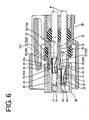
- the arm portion 22 projects more forward than the locking section 23 and is resiliently deformable outward or upward so as to at least partly retract into a deformation space 24 located above or radially outward (see FIG. 6).
- the rear surface of the locking section 23 to be pushed by the female terminal fitting 30 is slanted so that the resilient deformation of the arm portion 22 can be guided, whereas the front surface thereof is preferably formed to overhang or to be undercut so that the female terminal fitting 30 can be firmly held.
- Each female terminal fitting 30 is press-formed of a conductive (metallic) plate and is comprised of a main portion 31 preferably formed into a substantially rectangular tubular shape and provided inside with a resilient contact piece 33 to be resiliently brought into contact with a male terminal fitting (not shown), and barrel portions 32 (as preferred connection portions) to be crimped or bent or folded into connection with an end of the wire W.
- the locking section 23 of the locking portion 21 is engageable with a jaw portion 34 formed at the upper rear end of the main portion 31.
- a stabilizer 35 at least partly insertable into an insertion groove 26 formed in a (right) side wall 25 of the cavity 13 projects from the (right) side surface of the main portion 31.
- the retainer 40 preferably the front retainer 40, is made e.g. of a synthetic resin, mountable onto the terminal accommodating portion 11 preferably from front and comprised of a surrounding wall 41 substantially in the form of a rectangular tube for substantially surrounding the outer circumferential surface of the terminal accommodating portion 11, and a front wall 42 for at least partly covering the front surface of the terminal accommodating portion 11 as shown in FIGS. 1 and 3.
- Supporting walls 43 which can at least partly enter front spaces (spaces defined by cutting off portions of the upper walls 19 and the partition walls 20) of the respective upper and lower locking portions 21 in the housing 10 and support the female terminal fittings 30 at least partly inserted into the respective cavities 13 project backward from the front wall 42.
- a deformation restricting portion 44 for restricting the resilient deformation of the locking portion 21 by at least partly entering the deformation space 24 for the locking portion 21 projects substantially backward from each supporting wall 43.
- the deformation restricting portions 44 preferably have a thickness which is about half the thickness of the supporting walls 43.
- the retainer 40 (preferably the front retainer 40) is movable along a moving direction (preferably substantially forward and backward) with respect to the terminal accommodating portion 11 between a first position or partial locking position (see FIG. 3) where the deformation restricting portions 44 are located near or before the deformation spaces 24 for the locking portions 21 to permit the resilient deformation of the locking portions 21 and a second position or full locking position (see FIG. 7) where the deformation restricting portions 44 at least partly enter the deformation spaces 24 to prevent the locking portions 21 from being resiliently deformed.
- a pair of holding arms 45 each supported only at one end are formed at the opposite widthwise ends of the surrounding wall 41 of the front retainer 40 preferably by making slits.
- the front retainer 40 can be selectively held on the terminal accommodating portion 11 at the partial locking position (see FIG. 4) and the full locking position (see FIG. 8) by the engagement of the holding arms 45 with first or partial locking projections 27 and second or full locking projections 28 projecting from the outer side surfaces of the terminal accommodating portion 11.
- the front wall 42 is, as shown in FIG. 2, formed with male terminal fitting insertion holes 46 for permitting the at least partial insertion of the male terminal fittings into the cavities 13 and jig insertion holes 47 into which a jig for forcibly resiliently deforming the locking portion 21 in the deforming direction DD upon withdrawing the female terminal fitting 30 is at least partly insertable.
- the corresponding insertion holes 46 and 47 preferably are displaced along height and/or widthwise directions. Further, as shown in FIG. 3, the seal ring 15 preferably can be so held as not to come out forward by the surrounding wall 41.
- an engaging portion 29 projecting in the projecting direction PD to right or laterally (direction PD intersecting with resiliently deforming direction DD) from the lateral or right side surface of the arm portion 22 of each locking portion 21.
- Each engaging portion 29 and the right front end of the corresponding arm portion 22 are located at such a position as to be at least partly exposed to outside at front through the corresponding jig insertion hole 47 of the front retainer 40 as shown in FIG. 2, so that they can be pressed by the jig at least partly inserted into the jig insertion hole 47.
- suffix A is attached to the respective reference numbers of the cavities 13, the locking portions 21 and the engaging portions 29 at the upper stage and suffix B is attached to the respective reference numerals thereof at the lower stage in the case of distinguishing these elements at the upper and lower stages; and no suffix is attached in the case of collectively referring to them without distinguishing.
- each engaging portion 29A at the upper stage is coupled to the arm portion 22A over the substantially entire length of the arm portion 22A and to the front end surface of the upper wall 19, whereas each engaging portion 29B at the lower stage is coupled to the arm portion 22B over the substantially entire length of the arm portion 22B and to the front end surface of the partition wall 20, whereby the locking portions 21A, 21B are reinforced.
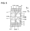
- the engaging portions 29A at the upper stage are located to substantially face an upper portion 41a of the surrounding wall 41 of the front retainer 40 mounted at the first or partial locking position, whereas the engaging portions 29B at the lower stage are located to substantially face corresponding right side walls 25A of the cavities 13A at the upper (front side with respect resiliently deforming direction DD) stage shown in FIG. 5.
- the side walls 25A extend substantially along vertical direction which is the resiliently deforming direction DD of the locking portions 21.
- the engaging portion 29A comes substantially into engagement with the upper portion 41a of the surrounding wall 41 before the locking portion 21A is resiliently deformed beyond its resiliency limit.
- the locking portion 21B at the lower stage is resiliently deformed, the engaging portion 29B comes into engagement with the lower surface of the side wall 25A before the locking portion 21B is resiliently deformed beyond its resiliency limit. In this way, the locking portions 21a, 21B are prevented from undergoing a plastic deformation by being excessively deformed.
- the upper portion 41 a of the surrounding wall 41 of the front retainer 40 preferably forms an excessive deformation preventing portion for the locking portions 21A at the upper stage, and the side walls 25A of the cavities 13 at the upper stage preferably form excessive deformation preventing portions for the locking portions 21B at the upper stage.
- the arm portion 22 is resiliently deformed in the deforming direction (e.g. upward or outward) and at least partly retracted into the deformation space 24 as the rear surface of the locking section 23 is pushed by the main portion 31 as shown in FIG. 6.
- This inserting operation is smoothly guided by the stabilizer 35 at least partly inserted into the insertion groove 26 (see FIG. 9).
- the arm portion 22 at least partly resiliently returns and the front surface of the locking section 23 is engaged with the jaw portion 34, whereby the female terminal fitting 30 is so held as not to come out of the cavity 13.
- the female terminal fitting 30 has a front half portion of the main portion 31 preferably supported by the supporting wall 43 of the front retainer 40 so as not to vertically or radially shake.
- the (front) retainer 40 is pushed from the first or partial locking position to the second or full locking position.
- the respective supporting walls 43 preferably support the substantially entire main portions 31 except their rear end portions and the respective deformation restricting portions 44 enter the corresponding deformation spaces 24 as shown in FIGS. 7 and 8. This prevents the locking portions 21 from being inadvertently resiliently deformed, with the result that the female terminal fittings 30 can be more strongly held so as not to come out.
- the female terminal fitting 30 may be withdrawn for maintenance or other reason.
- the jig is at least partly inserted into the jig insertion hole 47 preferably from front (see FIG. 2).
- the locking portion 21 is forcibly resiliently deformed by pushing the front ends of the arm portion 22 and the engaging portion 29 in the deforming direction DD (e.g. upward or outward) by means of the inserted jig.
- the female terminal fitting 30 is or can be pulled out of the cavity 13 after the locking section 23 is disengaged from the jaw portion 34.
- a force to operate the jig may become too large to excessively resiliently deform the locking portion 21.
- the engaging portion 29A is received by the upper portion 41a of the surrounding wall 41 of the front retainer 40 as shown in FIG. 9, thereby preventing the locking portion 21A from being excessively resiliently deformed beyond its resiliency limit.
- the engaging portion 29B is received by the lower surface of the (right) side wall 25A of the cavity 13A at the upper stage shown in FIG.
- each locking portion 21 is prevented from substantially undergoing a plastic deformation in this way, a function thereof to lock the female terminal fitting 30 can be securely displayed when the withdrawn female terminal fitting 30 is at least partly inserted into the cavity 13 again.
- the engaging portion 29B projecting in the direction PD intersecting with the resiliently deforming direction DD and facing the side wall 25A of the cavity 13A at the upper (front side with respect resiliently deforming direction DD) stage extending in the resiliently deforming direction DD is provided on the side surface of each locking portion 21B at the lower stage, and this engaging portion 29B is received by or interacts with the side wall 25A to prevent the excessive resilient deformation of the locking portion 21B.
- the connector can be miniaturized with respect to the resiliently deforming direction DD of the locking portions 21 as compared to a case where the excessive deformation preventing walls are provided between the locking portion and the cavities at the upper stage as in the prior art connector shown in FIG. 10.
- the engaging portion 29A projecting in the direction PD intersecting with the resiliently deforming direction DD and located to substantially face the surrounding wall 41 of the front retainer 40 is provided on the side surface of each locking portion 21A at the upper stage, and this engaging portion 29A is received by or interacts with the surrounding wall 41 to prevent the excessive resilient deformation of the locking portion 21A.
- the connector can be miniaturized with respect to the resiliently deforming direction DD of the locking portions 21 as compared to a case where the excessive deformation preventing walls and the surrounding wall of the front wall are arranged one over another along the resiliently deforming direction of the locking portions as in the prior art connector shown in FIG. 11.
- each engaging portion 29 is coupled to the arm portion 22 of the locking portion 21 preferably over the substantially entire length of the arm portion 22, the locking portion 21 can be reinforced to increase a force for holding the female terminal fitting 30.
- a housing 10 is provided with a terminal accommodating portion 11 formed with one or more cavities 13 arranged at two upper and lower stages, and a locking portion 21 projects in each cavity 13.
- Each locking portion 21 includes an arm portion 22 resiliently deformable upward and a locking section 23 engageable with a female terminal fitting 30.
- a (front) retainer 40 having deformation restricting portions 44 for preventing the resilient deformation of the locking portions 21 by entering deformation spaces 24 for the locking portions 21 is mounted or mountable on or to the terminal accommodating portion 11.
- Each arm portion 22 is provided with an engaging portion 29 projecting sideways or laterally or radially.
- Each engaging portion 29B at the lower stage is located to face a side wall 25A of the cavity 13A at the upper stage and received by the side wall 25A during the resilient deformation of the locking portion 21B, whereas each engaging portion 29A at the upper stage is located to face a surrounding wall 41 of the front retainer 40 and received by the surrounding wall 41 during the resilient deformation of the locking portion 21A.
- the respective locking portions 21 can be prevented from undergoing an excessive resilient deformation beyond their resiliency limit.
Landscapes
- Connector Housings Or Holding Contact Members (AREA)
Abstract
Description
- The present invention relates to a connector provided with locking portions.
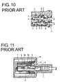
- An example of a multi-stage connector provided with locking portions for locking terminal fittings is known from Japanese Unexamined Patent Publication No. 6-325814. This connector is constructed as shown in FIG. 10.
Cavities 3 into whichterminal fittings 2 are insertable from behind are formed at two upper and lower stages in ahousing 3. Lockingportions 5 which are resiliently deformed upon being pressed by theterminal fittings 2 being inserted to retract intodeformation spaces 4 located above and return to engage and lock theterminal fittings 2 when theterminal fittings 2 reach proper depth project from the ceiling surfaces of therespective cavities 3. Above thedeformation spaces 4 in the housing 1 are provided excessivedeformation preventing walls 6 for preventing thelocking portions 5 from undergoing an excessive resilient deformation by receiving thelocking portions 5 before thelocking portions 5 are resiliently deformed beyond their resiliency limit. - An example of a connector provided with a front retainer for increasing a force for holding terminal fittings by restricting the resilient deformation of locking portions is known from Japanese Unexamined Patent Publication No. 5-47433. This connector is constructed as shown in FIG. 11. A housing 1 includes a terminal accommodating
portion 7 provided withcavities 3, lockingportions 5,deformation spaces 4 and excessivedeformation preventing walls 6, and afront retainer 8 having resilientdeformation restricting portions 8a for restricting the resilient deformation of thelocking portions 5 engaged withterminal fittings 2 by entering thedeformation spaces 4 is mounted onto theterminal accommodating portion 7 from front. Thefront retainer 8 has a surroundingwall 8b for surrounding the outer circumferential surface of theterminal accommodating portion 7 when thefront retainer 8 is mounted. - In the connector shown in FIG. 10, the
locking portions 5, thedeformation spaces 4 and the excessivedeformation preventing walls 6 are arranged one over another along height direction. On the other hand, in the connector shown in FIG. 11, thelocking portions 5, thedeformation spaces 4, the excessivedeformation preventing walls 6 and the surroundingwall 8b of thefront retainer 8 are arranged one over another along height direction. These two connectors have a problem of having a longer dimension along height direction. - The present invention was developed in view of the above problem and an object thereof is to miniaturize a connector.
- This object is solved according to the invention by a connector according to
claim 1 or 3. Preferred embodiments of the invention are subject of the dependent claims. - According to the invention, there is provided a connector, comprising:
- a connector housing formed with cavities into which terminal fittings are at least partly insertable, and locking portions each of which at least partly projects into the corresponding cavity and, after being resiliently deformed by the terminal fitting being inserted, at least partly returns to engage and lock the terminal fitting when the terminal fitting substantially reaches proper depth, wherein the cavities are arranged at a plurality of stages along a resiliently deforming direction of the locking portions,
-
- Since the engaging portion projecting in the direction intersecting with the resiliently deforming direction of the locking portion is received by the side wall extending along the resiliently deforming direction of the cavity located before this engaging portion with respect to the resiliently deforming direction to prevent the excessive resilient deformation of the locking portion, the connector can be miniaturized with respect to the resiliently deforming direction of the locking portions as compared to a case where excessive deformation preventing walls are provided between locking portions and cavities before them with respect to the resiliently deforming direction as in the prior art.
- According to a preferred embodiment of the invention, the connector further comprises a retainer being displaceable between a first position, where the terminal fittings are at least partly insertable into the respective cavities, and a second position, where the retainer engages the locking portions so as to doubly lock the terminal fittings in the respective cavities.
- According to the invention, there is further provided a connector, comprising:
- a connector housing formed with one or more cavities into which at least one corresponding terminal fitting is at least partly insertable, and one or more locking portions each of which at least partly projects into the corresponding cavity and, after being resiliently deformed by the terminal fitting being inserted, at least partly returns to engage and lock the terminal fitting when the terminal fitting substantially reaches proper depth, and
- a front retainer mountable into or onto the connector housing, having one or more deformation restricting portions for restricting the resilient deformation of the locking portions by entering corresponding deformation spaces for the locking portions, wherein each locking portion comprises an engaging portion projecting in a direction intersecting with a resiliently deforming direction of the locking portion and located to substantially face a wall portion of the front retainer, and each engaging portion is received by the wall portion to prevent the corresponding locking portion from undergoing an excessive resilient deformation.
-
- According to a preferred embodiment of the invention, the front retainer comprises a surrounding wall for at least partly surrounding the outer circumferential surface of the connector housing.
- According to a further preferred embodiment of the invention, there is provided a connector, comprising:
- a connector housing formed with cavities into which a terminal fitting is insertable, and locking portions each of which projects into the corresponding cavity and, after being resiliently deformed by the terminal fitting being inserted, returns to engage and lock the terminal fitting when the terminal fitting reaches proper depth, and
- a front retainer mountable into the connector housing, having a surrounding wall for surrounding the outer circumferential surface of the connector housing, and deformation restricting portions for restricting the resilient deformation of the locking portions by entering deformation spaces for the locking portions, wherein each locking portion comprises an engaging portion projecting in a direction intersecting with a resiliently deforming direction of the locking portion and located to face the surrounding wall, and each engaging portion is received by the surrounding wall to prevent the corresponding locking portion from undergoing an excessive resilient deformation.
-
- Since the engaging portion projecting in the direction intersecting with the resiliently deforming direction of the locking portion is received by the surrounding wall of the front retainer or the deformation restricting portion to prevent the excessive resilient deformation of the locking portion, the connector can be miniaturized with respect to the resiliently deforming direction of the locking portions as compared to a case where the deformation restricting portions and the surrounding wall of the front retainer are arranged one over the other along the resiliently deforming direction of the locking portions as in the prior art.
- Preferably, each engaging portion is coupled to the corresponding locking portion substantially over the entire length of the locking portion.
- The locking portions can be reinforced by the engaging portions. the engaging portion can interact with a jig at least partly inserted into the housing so as to deflect the locking portion in the deforming direction.
- Further preferably, the retainer comprises a front wall being formed with mating terminal fitting insertion holes for permitting the at least partial insertion of mating terminal fittings into the cavities and jig insertion holes into which a jig for forcibly resiliently deforming the locking portion in the deforming direction upon withdrawing the terminal fitting is at least partly insertable, wherein the corresponding insertion holes preferably are displaced along height and/or widthwise directions of the connector.
- Still further preferably, the retainer comprises a supporting portion for supporting a front portion of the terminal fitting(s) so as not to radially shake.
- Further preferably, a seal ring is provided on the housing so as to provide watertighness between the connector and a mating connector.
- Most preferably, the seal ring can be so held as not to come out preferably substantially forward by the surrounding wall.
- These and other objects, features and advantages of the present invention will become more apparent upon reading of the following detailed description of preferred embodiments and accompanying drawings. It should be understood that even though embodiments are separately described, single features thereof may be combined to additional embodiments.
- FIG. 1 is a front view of a housing and a front retainer according to one embodiment of the invention,
- FIG. 2 is a front view showing a state where the front retainer is mounted in the housing,
- FIG. 3 is a section along X-X of FIG. 2 showing a state where the front retainer is mounted at a partial locking position in the housing,
- FIG. 4 is a section along Y-Y of FIG. 2 showing the state where the front retainer is mounted at the partial locking position in the housing,
- FIG. 5 is a section along Z-Z of FIG. 3,
- FIG. 6 is a section along X-X of FIG. 2 showing an intermediate stage of insertion of female terminal fittings into cavities,
- FIG. 7 is a section along X-X of FIG. 2 showing a state where the female terminal fittings are properly inserted in the cavities and the front retainer is mounted at a full locking position in the housing,
- FIG. 8 is a section along Y-Y of FIG. 2 showing a state where the front retainer is mounted at the full locking position in the housing,
- FIG. 9 is a section along Z-Z of FIG. 3 showing a state where the excessive resilient deformation of locking portions is prevented,
- FIG. 10 is a section of a prior art connector, and
- FIG. 11 is a section of another prior art connector.
-
- One preferred embodiment of the present invention is described with reference to FIGS. 1 to 9. A multi-stage female connector preferably having a retainer (preferably a front retainer) is illustrated in this embodiment. This connector is roughly comprised of
female terminal fittings 30, ahousing 10 for at least partly accommodating thefemale terminal fittings 30, and preferably afront retainer 40 for restricting the resilient deformation oflocking portions 21. In the following description, a mating side with a mating connector (not shown) and the opposite side (e.g. left and right sides in FIGS. 3 and 4) are referred to as front and rear sides, respectively, and reference is made to FIGS. 1 and 3 concerning vertical direction. - The
housing 10 is made e.g. of a synthetic resin and, as shown in FIGS. 1 and 3, includes a terminal accommodatingportion 11 formed withcavities 13 into which thefemale terminal fittings 30 are at least partly insertable preferably from behind, and anouter tube portion 12 coupled to the outer circumferential surface of theterminal accommodating portion 11 and open forward. A mating male connector (not shown) is at least partly fittable from a mating side or front to be located between theterminal accommodating portion 11 and theouter tube portion 12, and alock arm 14 for locking the male and female connectors into each other projects from the upper surface of theterminal accommodating portion 11 while preferably being supported only at one end. Aseal ring 15 for providing watertightness between the male connector and thehousing 10 is preferably mounted or mountable on the outer circumferential surface of theterminal accommodating portion 11 at a position immediately before thelock arm 14. An accommodating recess 18 preferably for at least partly accommodating a one-piece rubber plug 16 for protecting therespective cavities 13 from the entrance of water and apressing member 17 for holding therubber plug 16 in position one after the other is formed in the rear surface of theterminal accommodating portion 11. Therubber plug 16 and thepressing member 17 are each formed with wire insertion holes through which wires W connected or connectable with thefemale terminal fittings 30 are or can be drawn out. - E.g. three
cavities 13 are arranged in widthwise direction at each of one or more, e.g. two upper and lower stages in the terminal accommodatingportion 11. Upper orlateral walls 19 of thecavities 13 at the upper stage and partition walls 20 (bottom or lateral walls of thecavities 13 at the upper stage and upper walls of thecavities 13 at the lower stage) partitioning the upper andlower cavities 13 are cut off from the front end position of theterminal accommodating portion 11 to a substantially longitudinal intermediate position, preferably substantially middle position thereof. Lockingportions 21 each supported preferably only at one end project substantially forward from the front end surfaces of theupper walls 19 and thepartition walls 20 in correspondence with therespective cavities 13. Each lockingportion 21 is engageable with the female terminal fitting 30 being inserted into thecavity 13 to hold the female terminal fitting 30 so as not to come out. Each lockingportion 21 is comprised of a substantially forward-extendingarm portion 22 and alocking section 23 projecting into thecavity 13 from a corresponding surface (preferably the bottom or inward surface) of thearm portion 22. Thearm portion 22 projects more forward than the lockingsection 23 and is resiliently deformable outward or upward so as to at least partly retract into adeformation space 24 located above or radially outward (see FIG. 6). The rear surface of thelocking section 23 to be pushed by the female terminal fitting 30 is slanted so that the resilient deformation of thearm portion 22 can be guided, whereas the front surface thereof is preferably formed to overhang or to be undercut so that the female terminal fitting 30 can be firmly held. - Each female terminal fitting 30 is press-formed of a conductive (metallic) plate and is comprised of a
main portion 31 preferably formed into a substantially rectangular tubular shape and provided inside with aresilient contact piece 33 to be resiliently brought into contact with a male terminal fitting (not shown), and barrel portions 32 (as preferred connection portions) to be crimped or bent or folded into connection with an end of the wire W. The lockingsection 23 of the lockingportion 21 is engageable with ajaw portion 34 formed at the upper rear end of themain portion 31. Further, as shown in FIG. 9, astabilizer 35 at least partly insertable into aninsertion groove 26 formed in a (right)side wall 25 of thecavity 13 projects from the (right) side surface of themain portion 31. - The
retainer 40, preferably thefront retainer 40, is made e.g. of a synthetic resin, mountable onto theterminal accommodating portion 11 preferably from front and comprised of a surroundingwall 41 substantially in the form of a rectangular tube for substantially surrounding the outer circumferential surface of theterminal accommodating portion 11, and afront wall 42 for at least partly covering the front surface of theterminal accommodating portion 11 as shown in FIGS. 1 and 3. Supportingwalls 43 which can at least partly enter front spaces (spaces defined by cutting off portions of theupper walls 19 and the partition walls 20) of the respective upper andlower locking portions 21 in thehousing 10 and support the femaleterminal fittings 30 at least partly inserted into therespective cavities 13 project backward from thefront wall 42. Adeformation restricting portion 44 for restricting the resilient deformation of the lockingportion 21 by at least partly entering thedeformation space 24 for the lockingportion 21 projects substantially backward from each supportingwall 43. Thedeformation restricting portions 44 preferably have a thickness which is about half the thickness of the supportingwalls 43. - The retainer 40 (preferably the front retainer 40) is movable along a moving direction (preferably substantially forward and backward) with respect to the
terminal accommodating portion 11 between a first position or partial locking position (see FIG. 3) where thedeformation restricting portions 44 are located near or before thedeformation spaces 24 for the lockingportions 21 to permit the resilient deformation of the lockingportions 21 and a second position or full locking position (see FIG. 7) where thedeformation restricting portions 44 at least partly enter thedeformation spaces 24 to prevent the lockingportions 21 from being resiliently deformed. As shown in FIG. 4, a pair of holdingarms 45 each supported only at one end are formed at the opposite widthwise ends of the surroundingwall 41 of thefront retainer 40 preferably by making slits. Thefront retainer 40 can be selectively held on theterminal accommodating portion 11 at the partial locking position (see FIG. 4) and the full locking position (see FIG. 8) by the engagement of the holdingarms 45 with first orpartial locking projections 27 and second orfull locking projections 28 projecting from the outer side surfaces of theterminal accommodating portion 11. - The
front wall 42 is, as shown in FIG. 2, formed with male terminal fitting insertion holes 46 for permitting the at least partial insertion of the male terminal fittings into thecavities 13 and jig insertion holes 47 into which a jig for forcibly resiliently deforming the lockingportion 21 in the deforming direction DD upon withdrawing the female terminal fitting 30 is at least partly insertable. The corresponding insertion holes 46 and 47 preferably are displaced along height and/or widthwise directions. Further, as shown in FIG. 3, theseal ring 15 preferably can be so held as not to come out forward by the surroundingwall 41. - As shown in FIG. 1, an engaging
portion 29 projecting in the projecting direction PD to right or laterally (direction PD intersecting with resiliently deforming direction DD) from the lateral or right side surface of thearm portion 22 of each lockingportion 21. Each engagingportion 29 and the right front end of thecorresponding arm portion 22 are located at such a position as to be at least partly exposed to outside at front through the correspondingjig insertion hole 47 of thefront retainer 40 as shown in FIG. 2, so that they can be pressed by the jig at least partly inserted into thejig insertion hole 47. In the following description, suffix A is attached to the respective reference numbers of thecavities 13, the lockingportions 21 and the engagingportions 29 at the upper stage and suffix B is attached to the respective reference numerals thereof at the lower stage in the case of distinguishing these elements at the upper and lower stages; and no suffix is attached in the case of collectively referring to them without distinguishing. - As shown in FIGS. 3 and 5, each engaging
portion 29A at the upper stage is coupled to thearm portion 22A over the substantially entire length of thearm portion 22A and to the front end surface of theupper wall 19, whereas each engagingportion 29B at the lower stage is coupled to thearm portion 22B over the substantially entire length of thearm portion 22B and to the front end surface of thepartition wall 20, whereby the lockingportions portions 29A at the upper stage are located to substantially face anupper portion 41a of the surroundingwall 41 of thefront retainer 40 mounted at the first or partial locking position, whereas the engagingportions 29B at the lower stage are located to substantially face correspondingright side walls 25A of thecavities 13A at the upper (front side with respect resiliently deforming direction DD) stage shown in FIG. 5. Theside walls 25A extend substantially along vertical direction which is the resiliently deforming direction DD of the lockingportions 21. When the lockingportion 21A at the upper stage is resiliently deformed in the deforming direction DD, the engagingportion 29A comes substantially into engagement with theupper portion 41a of the surroundingwall 41 before the lockingportion 21A is resiliently deformed beyond its resiliency limit. When the lockingportion 21B at the lower stage is resiliently deformed, the engagingportion 29B comes into engagement with the lower surface of theside wall 25A before the lockingportion 21B is resiliently deformed beyond its resiliency limit. In this way, the lockingportions 21a, 21B are prevented from undergoing a plastic deformation by being excessively deformed. In other words, theupper portion 41 a of the surroundingwall 41 of thefront retainer 40 preferably forms an excessive deformation preventing portion for thelocking portions 21A at the upper stage, and theside walls 25A of thecavities 13 at the upper stage preferably form excessive deformation preventing portions for the lockingportions 21B at the upper stage. - Next, the functions of this embodiment thus constructed are described. First, as shown in FIGS. 3 and 4, the
seal ring 15, the one-piece rubber plug 16 and the pressingmember 17 are mounted into thehousing 10, and the respective femaleterminal fittings 30 are at least partly inserted into the correspondingcavities 13 with the (front)retainer 40 mounted at the first or partial locking position. - During the insertion of the female terminal fitting 30 into the
cavity 13, thearm portion 22 is resiliently deformed in the deforming direction (e.g. upward or outward) and at least partly retracted into thedeformation space 24 as the rear surface of thelocking section 23 is pushed by themain portion 31 as shown in FIG. 6. This inserting operation is smoothly guided by thestabilizer 35 at least partly inserted into the insertion groove 26 (see FIG. 9). When the female terminal fitting 30 is inserted to proper depth in thecavity 13, thearm portion 22 at least partly resiliently returns and the front surface of thelocking section 23 is engaged with thejaw portion 34, whereby the female terminal fitting 30 is so held as not to come out of thecavity 13. At this stage, the female terminal fitting 30 has a front half portion of themain portion 31 preferably supported by the supportingwall 43 of thefront retainer 40 so as not to vertically or radially shake. - After the insertion of all the female
terminal fittings 30 is completed, the (front)retainer 40 is pushed from the first or partial locking position to the second or full locking position. When thefront retainer 40 reaches the second or full locking position, the respective supportingwalls 43 preferably support the substantially entiremain portions 31 except their rear end portions and the respectivedeformation restricting portions 44 enter thecorresponding deformation spaces 24 as shown in FIGS. 7 and 8. This prevents the lockingportions 21 from being inadvertently resiliently deformed, with the result that the femaleterminal fittings 30 can be more strongly held so as not to come out. - On the other hand, the female terminal fitting 30 may be withdrawn for maintenance or other reason. In such a case, after the
front retainer 40 is returned to the first or partial locking position to retract thedeformation restricting portions 44 forward from thedeformation spaces 24, the jig is at least partly inserted into thejig insertion hole 47 preferably from front (see FIG. 2). The lockingportion 21 is forcibly resiliently deformed by pushing the front ends of thearm portion 22 and the engagingportion 29 in the deforming direction DD (e.g. upward or outward) by means of the inserted jig. The female terminal fitting 30 is or can be pulled out of thecavity 13 after thelocking section 23 is disengaged from thejaw portion 34. - During this withdrawing operation, a force to operate the jig may become too large to excessively resiliently deform the locking
portion 21. For example, in the case of a possible excessive resilient deformation of the lockingportion 21A at the upper stage, the engagingportion 29A is received by theupper portion 41a of the surroundingwall 41 of thefront retainer 40 as shown in FIG. 9, thereby preventing the lockingportion 21A from being excessively resiliently deformed beyond its resiliency limit. On the other hand, in the case of a possible excessive resilient deformation of the lockingportion 21B at the lower stage, the engagingportion 29B is received by the lower surface of the (right)side wall 25A of thecavity 13A at the upper stage shown in FIG. 9, thereby preventing the lockingportion 21B from being excessively resiliently deformed beyond its resiliency limit. Since each lockingportion 21 is prevented from substantially undergoing a plastic deformation in this way, a function thereof to lock the female terminal fitting 30 can be securely displayed when the withdrawn female terminal fitting 30 is at least partly inserted into thecavity 13 again. - As described above, according to this embodiment, the engaging
portion 29B projecting in the direction PD intersecting with the resiliently deforming direction DD and facing theside wall 25A of thecavity 13A at the upper (front side with respect resiliently deforming direction DD) stage extending in the resiliently deforming direction DD is provided on the side surface of each lockingportion 21B at the lower stage, and this engagingportion 29B is received by or interacts with theside wall 25A to prevent the excessive resilient deformation of the lockingportion 21B. Thus, the connector can be miniaturized with respect to the resiliently deforming direction DD of the lockingportions 21 as compared to a case where the excessive deformation preventing walls are provided between the locking portion and the cavities at the upper stage as in the prior art connector shown in FIG. 10. - On the other hand, the engaging
portion 29A projecting in the direction PD intersecting with the resiliently deforming direction DD and located to substantially face the surroundingwall 41 of thefront retainer 40 is provided on the side surface of each lockingportion 21A at the upper stage, and this engagingportion 29A is received by or interacts with the surroundingwall 41 to prevent the excessive resilient deformation of the lockingportion 21A. Thus, the connector can be miniaturized with respect to the resiliently deforming direction DD of the lockingportions 21 as compared to a case where the excessive deformation preventing walls and the surrounding wall of the front wall are arranged one over another along the resiliently deforming direction of the locking portions as in the prior art connector shown in FIG. 11. - Further, since each engaging
portion 29 is coupled to thearm portion 22 of the lockingportion 21 preferably over the substantially entire length of thearm portion 22, the lockingportion 21 can be reinforced to increase a force for holding the female terminal fitting 30. - Accordingly, to miniaturize a connector, a
housing 10 is provided with aterminal accommodating portion 11 formed with one ormore cavities 13 arranged at two upper and lower stages, and a lockingportion 21 projects in eachcavity 13. Each lockingportion 21 includes anarm portion 22 resiliently deformable upward and alocking section 23 engageable with a female terminal fitting 30. A (front)retainer 40 havingdeformation restricting portions 44 for preventing the resilient deformation of the lockingportions 21 by enteringdeformation spaces 24 for the lockingportions 21 is mounted or mountable on or to theterminal accommodating portion 11. Eacharm portion 22 is provided with an engagingportion 29 projecting sideways or laterally or radially. Each engagingportion 29B at the lower stage is located to face aside wall 25A of thecavity 13A at the upper stage and received by theside wall 25A during the resilient deformation of the lockingportion 21B, whereas each engagingportion 29A at the upper stage is located to face a surroundingwall 41 of thefront retainer 40 and received by the surroundingwall 41 during the resilient deformation of the lockingportion 21A. As a result, therespective locking portions 21 can be prevented from undergoing an excessive resilient deformation beyond their resiliency limit. - The present invention is not limited to the above described and illustrated embodiment. For example, the following embodiments are also embraced by the technical scope of the present invention as defined in the claims. Beside the following embodiment, various changes can be made without departing from the scope and spirit of the present invention as defined in the claims.
- (1) Although the cavities are arranged at two stages in the connector in the foregoing embodiment, the present invention is also applicable to connectors in which the cavities are arranged at three or more stages. Further, the present invention is applicable to a connector having one stage of cavities provided that it has a front retainer.
- (2) Although the engaging portion is coupled to the arm portion over the entire length of the arm portion in the foregoing embodiment, it may be, for example, coupled to a part of the arm portion according to the present invention.
- (3) Although the connector provided with the front retainer is shown in the foregoing embodiment, the present invention is also applicable to connectors having no front retainer provided that cavities are arranged at a plurality of stages along the resiliently deforming direction DD of locking portions.
- (4) Although each locking portion is supported only at one end in the foregoing embodiment, the present invention is also applicable to locking portions supported at both ends.
- (5) Although the female connector provided with female terminal fittings is shown in the foregoing embodiment, male connectors provided with male terminal fittings are also embraced by the present invention.
- (6) Although the connector is provided with a watertight function in the foregoing embodiment, the present invention is also applicable to nonwatertight connectors.
- (7) Although the connector is provided with a front retainer in the foregoing embodiment, the present invention is also applicable to connectors having a side retainer being insertable laterally into the housing.
-
-
- 10
- housing (connector housing)
- 13(13A)
- cavity
- 21(21A,21B)
- locking portion
- 24
- deformation space
- 25A
- side wall
- 29(29A, 29B)
- engaging portion
- 30
- female terminal fitting (terminal fitting)
- 40
- front retainer
- 41
- surrounding wall
- 44
- deformation preventing portion
each locking portion comprises an engaging portion which projects in a direction intersecting with the resiliently deforming direction and is located to face a side wall of the cavity located before the locking portion with respect to the resiliently deforming direction, the side wall extending along the resiliently deforming direction, and
each engaging portion is received by the corresponding side wall to prevent the corresponding locking portion from undergoing an excessive resilient deformation.
Claims (10)
- A connector, comprising:a connector housing (10) formed with cavities (13) into which terminal fittings (30) are at least partly insertable, and locking portions (21) each of which at least partly projects into the corresponding cavity (13) and, after being resiliently deformed by the terminal fitting (30) being inserted, at least partly returns to engage and lock the terminal fitting (30) when the terminal fitting (30) substantially reaches proper depth,wherein the cavities (13) are arranged at a plurality of stages along a resiliently deforming direction (DD) of the locking portions (21),each locking portion (21) comprises an engaging portion (29) which projects in a direction (PD) intersecting with the resiliently deforming direction (DD) and is located to substantially face a side wall (25A) of the cavity (13) located before the locking portion (21) with respect to the resiliently deforming direction (DD), the side wall (25A) extending along the resiliently deforming direction (DD), andeach engaging portion (29) is received by the corresponding side wall (25A) to prevent the corresponding locking portion (21) from undergoing an excessive resilient deformation.
- A connector according to claim 1, further comprising a retainer (40) being displaceable between a first position (FIG. 3; 4), where the terminal fittings (30) are at least partly insertable into the respective cavities (13), and a second position (FIG. 6; 8), where the retainer (40) engages the locking portions (21) so as to doubly lock the terminal fittings (30) in the respective cavities (13).
- A connector, comprising:wherein each locking portion (21) comprises an engaging portion (29) projecting in a direction (PD) intersecting with a resiliently deforming direction (DD) of the locking portion (21) and located to substantially face a wall portion (41a) of the front retainer (40), and each engaging portion (29) is received by the wall portion (41a) to prevent the corresponding locking portion (21) from undergoing an excessive resilient deformation.a connector housing (10) formed with one or more cavities (13) into which at least one corresponding terminal fitting (30) is at least partly insertable, and one or more locking portions (21) each of which at least partly projects into the corresponding cavity (13) and, after being resiliently deformed by the terminal fitting (30) being inserted, at least partly returns to engage and lock the terminal fitting (30) when the terminal fitting (30) substantially reaches proper depth, anda front retainer (40) mountable into or onto the connector housing (10), having one or more deformation restricting portions (44) for restricting the resilient deformation of the locking portions (21) by entering corresponding deformation spaces (24) for the locking portions (21),
- A connector according to claim 3, wherein the front retainer (40) comprises a surrounding wall (41) for at least partly surrounding the outer circumferential surface of the connector housing (10).
- A connector according to one or more of the preceding claims, wherein each engaging portion (29) is coupled to the corresponding locking portion (21) substantially over the entire length of the locking portion (21).
- A connector according to one or more of the preceding claims, wherein the engaging portion (29) can interact with a jig at least partly inserted into the housing (10) so as to deflect the locking portion (21) in the deforming direction (DD).
- A connector according to one or more of the preceding claims, wherein the retainer (40) comprises a front wall (42) being formed with mating terminal fitting insertion holes (46) for permitting the at least partial insertion of mating terminal fittings into the cavities (13) and jig insertion holes (47) into which a jig for forcibly resiliently deforming the locking portion (21) in the deforming direction (DD) upon withdrawing the terminal fitting (30) is at least partly insertable, wherein the corresponding insertion holes (46, 47) preferably are displaced along height and/or widthwise directions of the connector.
- A connector according to one or more of the preceding claims, wherein the retainer (40) comprises a supporting portion (43) for supporting a front portion of the terminal fitting(s) (30) so as not to radially shake.
- A connector according to one or more of the preceding claims, wherein a seal ring (15) is provided on the housing (10) so as to provide watertighness between the connector and a mating connector.
- A connector according to claim 9 and claim 4, wherein the seal ring (15) can be so held as not to come out preferably substantially forward by the surrounding wall (41).
Applications Claiming Priority (2)
| Application Number | Priority Date | Filing Date | Title |
|---|---|---|---|
| JP2002104399A JP3969161B2 (en) | 2002-04-05 | 2002-04-05 | connector |
| JP2002104399 | 2002-04-05 |
Publications (2)
| Publication Number | Publication Date |
|---|---|
| EP1351339A1 true EP1351339A1 (en) | 2003-10-08 |
| EP1351339B1 EP1351339B1 (en) | 2007-11-14 |
Family
ID=28035965
Family Applications (1)
| Application Number | Title | Priority Date | Filing Date |
|---|---|---|---|
| EP03007456A Expired - Lifetime EP1351339B1 (en) | 2002-04-05 | 2003-04-03 | A miniaturised connector |
Country Status (4)
| Country | Link |
|---|---|
| US (1) | US6817901B2 (en) |
| EP (1) | EP1351339B1 (en) |
| JP (1) | JP3969161B2 (en) |
| DE (1) | DE60317400T2 (en) |
Cited By (7)
| Publication number | Priority date | Publication date | Assignee | Title |
|---|---|---|---|---|
| FR2875957A1 (en) * | 2004-09-29 | 2006-03-31 | Fci Sa | DEVICE FOR LATCHING CONNECTOR ELEMENTS AND CONNECTOR COMPRISING SAME |
| WO2006131610A1 (en) * | 2005-06-09 | 2006-12-14 | Fci | Sealed connector with sequential closure |
| WO2007017560A1 (en) * | 2005-08-09 | 2007-02-15 | Fci | Connector sealing device |
| EP2124298A1 (en) | 2008-04-25 | 2009-11-25 | Molex Incorporated | Connector with TPA position dectection |
| EP2437357A1 (en) * | 2010-10-01 | 2012-04-04 | Sumitomo Wiring Systems, Ltd. | Connector |
| WO2013013967A1 (en) * | 2011-07-08 | 2013-01-31 | Fci Automotive Holding | Connector and connector assembly |
| EP3402003A1 (en) * | 2017-05-11 | 2018-11-14 | TE Connectivity Germany GmbH | Plug and method of attaching a vibration protection to a plug |
Families Citing this family (9)
| Publication number | Priority date | Publication date | Assignee | Title |
|---|---|---|---|---|
| JP3960431B2 (en) * | 2003-10-16 | 2007-08-15 | タイコエレクトロニクスアンプ株式会社 | Electrical connector |
| JP4241352B2 (en) * | 2003-12-05 | 2009-03-18 | 住友電装株式会社 | connector |
| DE102008015214A1 (en) * | 2007-03-28 | 2008-10-09 | Sumitomo Wiring Systems, Ltd., Yokkaichi | Interconnects |
| US7625251B2 (en) * | 2007-09-25 | 2009-12-01 | Tyco Electronics Corporation | Connector with redundant terminal locking |
| JP4963287B2 (en) * | 2007-11-16 | 2012-06-27 | 矢崎総業株式会社 | connector |
| US7824218B2 (en) * | 2008-09-30 | 2010-11-02 | Amphenol Corporation | Contact holder assembly |
| JP2013187126A (en) * | 2012-03-09 | 2013-09-19 | Yazaki Corp | Connector |
| JP2014203633A (en) * | 2013-04-04 | 2014-10-27 | 住友電装株式会社 | Connector |
| JP2016110833A (en) * | 2014-12-05 | 2016-06-20 | 富士通コンポーネント株式会社 | connector |
Citations (2)
| Publication number | Priority date | Publication date | Assignee | Title |
|---|---|---|---|---|
| US5645452A (en) * | 1994-06-17 | 1997-07-08 | Yazaki Corporation | Connector housing |
| EP1032080A1 (en) * | 1996-07-30 | 2000-08-30 | Sumitomo Wiring Systems, Ltd. | A connector |
Family Cites Families (9)
| Publication number | Priority date | Publication date | Assignee | Title |
|---|---|---|---|---|
| JPH0547433A (en) | 1991-08-16 | 1993-02-26 | Kansei Corp | Electric connector |
| JP2627135B2 (en) | 1993-05-14 | 1997-07-02 | 日本航空電子工業株式会社 | connector |
| JP3542710B2 (en) * | 1998-02-20 | 2004-07-14 | 矢崎総業株式会社 | connector |
| JP3638095B2 (en) * | 1999-06-11 | 2005-04-13 | 矢崎総業株式会社 | Terminal incomplete insertion detection structure |
| US6126484A (en) * | 1999-11-01 | 2000-10-03 | The Whitaker Corporation | Electrical connector with molded latch stop |
| JP3601772B2 (en) * | 1999-12-08 | 2004-12-15 | 矢崎総業株式会社 | connector |
| JP3635629B2 (en) * | 2000-03-14 | 2005-04-06 | 矢崎総業株式会社 | connector |
| JP2002008769A (en) * | 2000-06-27 | 2002-01-11 | Yazaki Corp | connector |
| EP1376768B1 (en) * | 2002-06-06 | 2004-10-27 | Sumitomo Wiring Systems, Ltd. | An electrical connector |
-
2002
- 2002-04-05 JP JP2002104399A patent/JP3969161B2/en not_active Expired - Fee Related
-
2003
- 2003-04-02 US US10/406,093 patent/US6817901B2/en not_active Expired - Fee Related
- 2003-04-03 EP EP03007456A patent/EP1351339B1/en not_active Expired - Lifetime
- 2003-04-03 DE DE60317400T patent/DE60317400T2/en not_active Expired - Lifetime
Patent Citations (2)
| Publication number | Priority date | Publication date | Assignee | Title |
|---|---|---|---|---|
| US5645452A (en) * | 1994-06-17 | 1997-07-08 | Yazaki Corporation | Connector housing |
| EP1032080A1 (en) * | 1996-07-30 | 2000-08-30 | Sumitomo Wiring Systems, Ltd. | A connector |
Cited By (15)
| Publication number | Priority date | Publication date | Assignee | Title |
|---|---|---|---|---|
| US7785146B2 (en) | 2004-09-29 | 2010-08-31 | Fci | Locking device for connector elements and a connector provided with said device |
| WO2006034865A1 (en) * | 2004-09-29 | 2006-04-06 | Fci | Locking device for connector elements and a connector provided with said device |
| FR2875957A1 (en) * | 2004-09-29 | 2006-03-31 | Fci Sa | DEVICE FOR LATCHING CONNECTOR ELEMENTS AND CONNECTOR COMPRISING SAME |
| KR100895547B1 (en) * | 2004-09-29 | 2009-04-29 | 에프씨아이 | Locking device for connector elements and a connector provided with said device |
| WO2006131610A1 (en) * | 2005-06-09 | 2006-12-14 | Fci | Sealed connector with sequential closure |
| CN101199086B (en) * | 2005-06-09 | 2011-02-09 | Fci公司 | Sequential Closure Sealed Connectors |
| WO2007017560A1 (en) * | 2005-08-09 | 2007-02-15 | Fci | Connector sealing device |
| EP2124298A1 (en) | 2008-04-25 | 2009-11-25 | Molex Incorporated | Connector with TPA position dectection |
| EP2437357A1 (en) * | 2010-10-01 | 2012-04-04 | Sumitomo Wiring Systems, Ltd. | Connector |
| CN102447185A (en) * | 2010-10-01 | 2012-05-09 | 住友电装株式会社 | Connector |
| AU2011224127B2 (en) * | 2010-10-01 | 2014-06-05 | Sumitomo Wiring Systems, Ltd. | Connector |
| WO2013013967A1 (en) * | 2011-07-08 | 2013-01-31 | Fci Automotive Holding | Connector and connector assembly |
| EP3402003A1 (en) * | 2017-05-11 | 2018-11-14 | TE Connectivity Germany GmbH | Plug and method of attaching a vibration protection to a plug |
| JP2018190727A (en) * | 2017-05-11 | 2018-11-29 | ティーイー コネクティビティ ジャーマニー ゲゼルシャフト ミット ベシュレンクテル ハフツンクTE Connectivity Germany GmbH | Plug and method of attaching vibration protection to plug |
| JP7133347B2 (en) | 2017-05-11 | 2022-09-08 | ティーイー コネクティビティ ジャーマニー ゲゼルシャフト ミット ベシュレンクテル ハフツンク | Plugs and methods of imparting vibration protection to plugs |
Also Published As
| Publication number | Publication date |
|---|---|
| JP2003297474A (en) | 2003-10-17 |
| US20030207616A1 (en) | 2003-11-06 |
| EP1351339B1 (en) | 2007-11-14 |
| DE60317400D1 (en) | 2007-12-27 |
| US6817901B2 (en) | 2004-11-16 |
| DE60317400T2 (en) | 2008-09-18 |
| JP3969161B2 (en) | 2007-09-05 |
Similar Documents
| Publication | Publication Date | Title |
|---|---|---|
| EP1211757B1 (en) | Elektrical connector | |
| EP1923962B1 (en) | A connector and method of preassembling it | |
| EP1351339B1 (en) | A miniaturised connector | |
| US6659797B2 (en) | Connector with resiliently deflectable lock arm | |
| US6520788B2 (en) | Watertight connector and sealing member | |
| EP1560298B1 (en) | A divided connector and connector assembly | |
| US6568948B2 (en) | Connector | |
| EP1083639B1 (en) | A connector | |
| US6497591B2 (en) | Connector | |
| EP1376769B1 (en) | Connector with resilient locking member | |
| CN110581370B (en) | Terminals and Connectors | |
| US6641437B2 (en) | Connector | |
| US6872093B2 (en) | Terminal fitting and a connector provided therewith | |
| US6851987B2 (en) | Connector | |
| EP1587174B1 (en) | A connector and a connector assembly | |
| US20020081912A1 (en) | Connector | |
| US7753613B2 (en) | Connector | |
| US7306486B2 (en) | Connector | |
| US6814618B2 (en) | Connector with resilient coupling pieces coupling locks in adjacent cavities | |
| US20040253884A1 (en) | Connector and a connector assembly | |
| EP1801926B1 (en) | A connetor and connector assembly | |
| EP1385235A1 (en) | Electrical connector | |
| JP4076590B2 (en) | Connector with retainer | |
| US7001224B2 (en) | Connector with retainer for locking terminal fitings | |
| JP2000150052A (en) | connector |
Legal Events
| Date | Code | Title | Description |
|---|---|---|---|
| PUAI | Public reference made under article 153(3) epc to a published international application that has entered the european phase |
Free format text: ORIGINAL CODE: 0009012 |
|
| AK | Designated contracting states |
Kind code of ref document: A1 Designated state(s): AT BE BG CH CY CZ DE DK EE ES FI FR GB GR HU IE IT LI LU MC NL PT SE SI SK TR |
|
| AX | Request for extension of the european patent |
Extension state: AL LT LV MK RO |
|
| 17P | Request for examination filed |
Effective date: 20031106 |
|
| AKX | Designation fees paid |
Designated state(s): DE FR |
|
| 17Q | First examination report despatched |
Effective date: 20060314 |
|
| GRAP | Despatch of communication of intention to grant a patent |
Free format text: ORIGINAL CODE: EPIDOSNIGR1 |
|
| GRAS | Grant fee paid |
Free format text: ORIGINAL CODE: EPIDOSNIGR3 |
|
| GRAA | (expected) grant |
Free format text: ORIGINAL CODE: 0009210 |
|
| AK | Designated contracting states |
Kind code of ref document: B1 Designated state(s): DE FR |
|
| REF | Corresponds to: |
Ref document number: 60317400 Country of ref document: DE Date of ref document: 20071227 Kind code of ref document: P |
|
| ET | Fr: translation filed | ||
| PLBE | No opposition filed within time limit |
Free format text: ORIGINAL CODE: 0009261 |
|
| STAA | Information on the status of an ep patent application or granted ep patent |
Free format text: STATUS: NO OPPOSITION FILED WITHIN TIME LIMIT |
|
| 26N | No opposition filed |
Effective date: 20080815 |
|
| PGFP | Annual fee paid to national office [announced via postgrant information from national office to epo] |
Ref country code: DE Payment date: 20130327 Year of fee payment: 11 |
|
| PGFP | Annual fee paid to national office [announced via postgrant information from national office to epo] |
Ref country code: FR Payment date: 20130625 Year of fee payment: 11 |
|
| REG | Reference to a national code |
Ref country code: DE Ref legal event code: R119 Ref document number: 60317400 Country of ref document: DE |
|
| REG | Reference to a national code |
Ref country code: FR Ref legal event code: ST Effective date: 20141231 |
|
| REG | Reference to a national code |
Ref country code: DE Ref legal event code: R119 Ref document number: 60317400 Country of ref document: DE Effective date: 20141101 |
|
| PG25 | Lapsed in a contracting state [announced via postgrant information from national office to epo] |
Ref country code: DE Free format text: LAPSE BECAUSE OF NON-PAYMENT OF DUE FEES Effective date: 20141101 |
|
| PG25 | Lapsed in a contracting state [announced via postgrant information from national office to epo] |
Ref country code: FR Free format text: LAPSE BECAUSE OF NON-PAYMENT OF DUE FEES Effective date: 20140430 |